EP1168121A2 - Data acquisition for remote monitoring system and method for remote monitoring - Google Patents
Data acquisition for remote monitoring system and method for remote monitoring Download PDFInfo
- Publication number
- EP1168121A2 EP1168121A2 EP01305423A EP01305423A EP1168121A2 EP 1168121 A2 EP1168121 A2 EP 1168121A2 EP 01305423 A EP01305423 A EP 01305423A EP 01305423 A EP01305423 A EP 01305423A EP 1168121 A2 EP1168121 A2 EP 1168121A2
- Authority
- EP
- European Patent Office
- Prior art keywords
- data
- computer system
- auxiliary processor
- processor
- central
- Prior art date
- Legal status (The legal status is an assumption and is not a legal conclusion. Google has not performed a legal analysis and makes no representation as to the accuracy of the status listed.)
- Withdrawn
Links
Images

Classifications
-
- G—PHYSICS
- G05—CONTROLLING; REGULATING
- G05B—CONTROL OR REGULATING SYSTEMS IN GENERAL; FUNCTIONAL ELEMENTS OF SUCH SYSTEMS; MONITORING OR TESTING ARRANGEMENTS FOR SUCH SYSTEMS OR ELEMENTS
- G05B19/00—Programme-control systems
- G05B19/02—Programme-control systems electric
- G05B19/04—Programme control other than numerical control, i.e. in sequence controllers or logic controllers
- G05B19/042—Programme control other than numerical control, i.e. in sequence controllers or logic controllers using digital processors
- G05B19/0421—Multiprocessor system
Definitions
- This invention relates generally to remote diagnostic monitoring of rotating machinery such as, but not limited to, gas turbines and more particularly to systems and methods for collecting and analyzing data used for such diagnostic monitoring.
- Gas turbines are used for a variety of applications such as driving an electric generator in a power generating plant or propelling a ship or an aircraft.
- gas turbines are routinely subject to various maintenance procedures as part of their normal operation.
- monitoring systems are often employed to provide diagnostic monitoring of the gas turbine.
- These systems commonly include performance monitoring equipment that collects relevant trend and fault data used for diagnostic trending.
- certain process data such as exhaust gas temperature, fuel flow, rotor speed and the like
- Any divergence of the raw trend data from the parametric baseline may be indicative of a present or future condition that requires maintenance.
- Such data can be recorded locally and accessed later by maintenance personnel or, alternatively, can be transmitted to a remote location so that a number of gas turbines can be remotely monitored at a central site.
- Gas turbines like all rotating machinery, are subject to vibrations due to causes such as rotor imbalance, misalignment of components, and worn or defective bearings. Thus, it is useful to monitor vibration and/or other dynamic gas turbine data in addition to the static gas turbine process data discussed above.
- transmitting dynamic signal data from the field units to the central site in a remote monitoring system can be difficult.
- remote monitoring of process and dynamic data is typically accomplished by using two computers on-site: one for collecting and processing the dynamic data and another for collecting and processing the process data.
- the above-mentioned need is met by the present invention which provides a remote monitoring system having a central computer system and at least one data acquisition unit for collecting data from a machine to be monitored.
- the data acquisition unit includes an on-site computer system having a central processor and an auxiliary processor.
- the data acquisition unit further includes a means for generating a process data signal and a means for generating a dynamic data signal.
- the process data signal is fed to the central processor and the auxiliary processor, and the dynamic data signal is fed to the auxiliary processor.
- a communication link connects the central computer system and the on-site computer system.
- Figure 1 shows a distributed remote monitoring system 10 that is capable of continuous diagnostic monitoring of rotating machinery 12 located at geographically dispersed locations.
- the rotating machinery 12 comprises a number of gas turbines that may be located in different power generating plants or on different ships or aircraft.
- the rotating machinery 12 is not limited to gas turbines and can be any type of machinery having rotative components such as compressors, pumps, blowers and the like.
- a separate data acquisition unit 14 is associated with each rotating machine 12.
- the data acquisition units 14 collect data from the corresponding machines 12 and transfer the data to a central monitoring station 16 via respective communication links 18.
- the data is processed at the data acquisition units 14 and analyzed at the central monitoring station 16.
- the communication links 18 can be any type of transmission link such as, but not limited to, telephone lines or the Internet.
- the data acquisition unit 14 includes an on-site computer system 20, one or more process data sensors 22, and one or more dynamic data sensors 24.
- the process data sensors 22 communicate with the machine 12 to be monitored to sense process data that are indicative of the overall performance and/or condition of the machine 12.
- the process data sensors 22 can be any type of performance monitoring equipment, instrumentation or equivalent means capable of sensing the machine process data. In the case of a gas turbine, the process data sensors 22 would ordinarily be incorporated into the gas turbine control system.
- the dynamic data sensors 24 communicate with the machine 12 to sense dynamic data (such as but not limited to vibration data) which relate to the operation of the machine 12.
- dynamic data such as but not limited to vibration data
- the dynamic data sensors 24 would be of the type that convert mechanical motion or energy into electrical signals.
- the dynamic data sensors 24 may be proximity probes, accelerometers or any means for sensing vibrations.
- the on-site computer system 20, which can be any type of computer system such as a PC, includes a primary or central processor such as a central processing unit (CPU) 26, an auxiliary processor 28 and an on-site database 30.
- the process data sensors 22 generate process data signals that are fed to the CPU 26 via an interface 32, which may be a standard RS/Ethernet interface.
- the process data signals are also fed to the auxiliary processor 28 via another interface 34, which may be an analog coaxial cable.
- the dynamic data sensors 24 generate dynamic data signals that are fed to the auxiliary processor 28 via an interface 36, which may also be an analog coaxial cable.
- the CPU 26 processes the inputted process data signals to permit diagnosis and prediction of performance related issues for the machine 12 (a process commonly known as trending). Specifically, appropriate trend parameters are calculated from the raw process data signals, and signals representative of the calculated trend parameters are stored in the on-site database 30. The trend parameter signals are also transmitted to the central monitoring station 16 via the communication link 18. The trend parameter signals are viewed at the central monitoring station 16 and compared to a parametric baseline for the machine 12 to detect symptoms indicative of a need for inspection or maintenance. That is, a divergence of the trend parameter signals from the parametric baseline may be indicative of a need to inspect and/or service the machine 12.
- the parametric baseline is generally empirically derived or generated from a model of the machine 12.
- the auxiliary processor 28 processes the inputted process data and dynamic data signals to generate an amplitude spectrum that represents the dynamic data. For example, if the dynamic data sensors 24 sense machine vibration data, then the auxiliary processor 28 would generate a vibration amplitude spectrum for the machine 12.
- the amplitude spectrum is stored in the on-site database 30 simultaneously with the trend parameter signals.
- the amplitude spectrum is also transmitted to the central monitoring station 16 via the communication link 18 for viewing and analysis. As will be described in more detail below, the amplitude spectrum can be viewed in real time along side the trend parameter signals.
- the amplitude spectrum is compared to a baseline to diagnose and predict maintenance issues. For instance, the amplitude spectrum could represent a vibration amplitude spectrum that would be compared to a previously obtained, benchmark vibration signature for the machine 12.
- the auxiliary processor 28 is an expansion board that is inserted into an expansion slot of the on-site computer system 20.
- the expansion board 28 includes a signal analysis algorithm, such as a fast Fourier transform (FFT) algorithm that performs the processing of the inputted process data and dynamic data signals. More specifically, the expansion board 28 takes the dynamic data signals from the dynamic data sensors 24 into an analog-to-digital converter. These signals are then compared against the output of remotely configurable tracking filters to obtain the amplitude spectrum.
- the tracking filters use the process data signals from the process data sensors 22 and permit predetermined frequencies of the machine 12 to be isolated for analysis.
- the filters could be used to track the primary frequency, which is a function of the turbine rotor speed, of the gas turbine 12. Generally, there is a maximum of four filters per channel.
- the expansion board 28 could be an off-the-shelf product such as the BN4000 Processor board commercially available from Bridgenorth Signal Processing, Inc. of Blaine, Washington.
- the on-site computer system 20 includes an interface software application 38 for providing an interface between the CPU 26 and the auxiliary processor 28.
- the interface software application 38 allows the amplitude spectrum (or a subset thereof) to be transmitted and viewed on a time coherent basis with the trend parameter signals.
- the trend parameter signals and the amplitude spectrum can be viewed on the same screen at the same time.
- the trend parameter signals and the amplitude spectrum are both transmitted to the central monitoring station 16 via the communication link 18.
- the central monitoring station 16 includes a central computer system 40 and a central database 42.
- a display 44 is associated with the central computer system 40 for displaying the trend parameter signals and the amplitude spectrum.
- the interface software application 38 is a modification of the Cimplicity data processing software available from GE Fanuc Automation North America, Inc of Charlottesville, Virginia.
- Cimplicity software is an application that takes in data, logs the data into a database, and permits the data to be displayed for visual review.
- the software application used in the present invention is modified so as to first convert the data processed by the auxiliary processor 28 into a form that is compatible with the Cimplicity-based interface software application.
- the interface software application 38 then causes the converted form of the amplitude spectrum to be displayed (on the display 44) for visual review in the same manner that standard Cimplicity software displays data.
- the trend parameter signals and the amplitude spectrum are stored in the on-site database 30.
- the trend parameter signals and the amplitude spectrum, upon transmission to the central monitoring station 16, are also stored in the central database 42.
- the display 44 can display real time data or data retrieved from the central database 42.
- the trend parameter signals and the amplitude spectrum are logged into the on-site database 30 at a high rate (such as once per second) and are logged into the central database 42 at a lower rate (such as once per minute).
- the trend parameter signals and the amplitude spectrum are logged into the central database 42 at a lower rate because the data is being transmitted from the on-site computer system 20.
- a high rate of storage would require an enormous amount of data transmission.
- the trend parameter signals and the amplitude spectrum can be stored on the on-site database 30 at a higher rate because of its proximity. Storing the trend parameter signals and the amplitude spectrum on the on-site database 30 provides high resolution data that can be accessed as needed. For instance, if there is a machine malfunction or other event in which high resolution data is needed to resolve the problem, then the high resolution data can be accessed from the on-site database 30.
- the high resolution data is typically maintained on the on-site database 30 for a set period of time, such as 10 days.
Abstract
Description
- This invention relates generally to remote diagnostic monitoring of rotating machinery such as, but not limited to, gas turbines and more particularly to systems and methods for collecting and analyzing data used for such diagnostic monitoring.
- Gas turbines are used for a variety of applications such as driving an electric generator in a power generating plant or propelling a ship or an aircraft. In any application, gas turbines are routinely subject to various maintenance procedures as part of their normal operation. To aid in the provision of such maintenance services, monitoring systems are often employed to provide diagnostic monitoring of the gas turbine. These systems commonly include performance monitoring equipment that collects relevant trend and fault data used for diagnostic trending. In diagnostic trend analysis, certain process data (such as exhaust gas temperature, fuel flow, rotor speed and the like) that are indicative of overall gas turbine performance and/or condition are compared to a parametric baseline for the gas turbine. Any divergence of the raw trend data from the parametric baseline may be indicative of a present or future condition that requires maintenance. Such data can be recorded locally and accessed later by maintenance personnel or, alternatively, can be transmitted to a remote location so that a number of gas turbines can be remotely monitored at a central site.
- Gas turbines, like all rotating machinery, are subject to vibrations due to causes such as rotor imbalance, misalignment of components, and worn or defective bearings. Thus, it is useful to monitor vibration and/or other dynamic gas turbine data in addition to the static gas turbine process data discussed above. However, transmitting dynamic signal data from the field units to the central site in a remote monitoring system can be difficult. At present, remote monitoring of process and dynamic data is typically accomplished by using two computers on-site: one for collecting and processing the dynamic data and another for collecting and processing the process data.
- One drawback with this approach is the cost of providing and maintaining two separate computers. Another is an inability to analyze the dynamic and process signals in a time coherent manner. When analyzing such data, the ability to review the dynamic and process signals on a simultaneous or time coherent basis provides a better understanding of the overall gas turbine condition. But the current two-computer system does not provide for time coherent review.
- Accordingly, it would be desirable to be able to remotely monitor dynamic and process signals at the same time using a single computer system.
- The above-mentioned need is met by the present invention which provides a remote monitoring system having a central computer system and at least one data acquisition unit for collecting data from a machine to be monitored. The data acquisition unit includes an on-site computer system having a central processor and an auxiliary processor. The data acquisition unit further includes a means for generating a process data signal and a means for generating a dynamic data signal. The process data signal is fed to the central processor and the auxiliary processor, and the dynamic data signal is fed to the auxiliary processor. A communication link connects the central computer system and the on-site computer system.
- The present invention and its advantages over the prior art will become apparent upon reading the following detailed description and the appended claims with reference to the accompanying drawings , in which:
- Figure 1 is a schematic diagram of a distributed remote monitoring system.
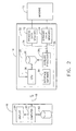
- Figure 2 is a block diagram showing a portion of the remote monitoring system of Figure 1 in greater detail.
- Referring to the drawings wherein identical reference numerals denote the same elements throughout the various views, Figure 1 shows a distributed
remote monitoring system 10 that is capable of continuous diagnostic monitoring of rotatingmachinery 12 located at geographically dispersed locations. In the illustrated example, therotating machinery 12 comprises a number of gas turbines that may be located in different power generating plants or on different ships or aircraft. However, therotating machinery 12 is not limited to gas turbines and can be any type of machinery having rotative components such as compressors, pumps, blowers and the like. - A separate
data acquisition unit 14 is associated with eachrotating machine 12. Thedata acquisition units 14 collect data from thecorresponding machines 12 and transfer the data to acentral monitoring station 16 viarespective communication links 18. In one embodiment, the data is processed at thedata acquisition units 14 and analyzed at thecentral monitoring station 16. Thecommunication links 18 can be any type of transmission link such as, but not limited to, telephone lines or the Internet. - Turning now to Figure 2, a portion of the remote monitoring system 10 (i.e., the
central monitoring station 16 and one of the data acquisition units 14) is shown in greater detail. Thedata acquisition unit 14 includes an on-site computer system 20, one or moreprocess data sensors 22, and one or moredynamic data sensors 24. Theprocess data sensors 22 communicate with themachine 12 to be monitored to sense process data that are indicative of the overall performance and/or condition of themachine 12. Theprocess data sensors 22 can be any type of performance monitoring equipment, instrumentation or equivalent means capable of sensing the machine process data. In the case of a gas turbine, theprocess data sensors 22 would ordinarily be incorporated into the gas turbine control system. Examples of typical process data monitored for a gas turbine include, but are not limited to, exhaust gas temperature, fuel flow, rotor speeds, compressor discharge pressure, turbine exhaust pressure, and the like. Thedynamic data sensors 24 communicate with themachine 12 to sense dynamic data (such as but not limited to vibration data) which relate to the operation of themachine 12. When monitoring vibration data, thedynamic data sensors 24 would be of the type that convert mechanical motion or energy into electrical signals. For example, thedynamic data sensors 24 may be proximity probes, accelerometers or any means for sensing vibrations. - The on-
site computer system 20, which can be any type of computer system such as a PC, includes a primary or central processor such as a central processing unit (CPU) 26, anauxiliary processor 28 and an on-site database 30. Theprocess data sensors 22 generate process data signals that are fed to theCPU 26 via aninterface 32, which may be a standard RS/Ethernet interface. The process data signals are also fed to theauxiliary processor 28 via anotherinterface 34, which may be an analog coaxial cable. Thedynamic data sensors 24 generate dynamic data signals that are fed to theauxiliary processor 28 via aninterface 36, which may also be an analog coaxial cable. - The
CPU 26 processes the inputted process data signals to permit diagnosis and prediction of performance related issues for the machine 12 (a process commonly known as trending). Specifically, appropriate trend parameters are calculated from the raw process data signals, and signals representative of the calculated trend parameters are stored in the on-site database 30. The trend parameter signals are also transmitted to thecentral monitoring station 16 via thecommunication link 18. The trend parameter signals are viewed at thecentral monitoring station 16 and compared to a parametric baseline for themachine 12 to detect symptoms indicative of a need for inspection or maintenance. That is, a divergence of the trend parameter signals from the parametric baseline may be indicative of a need to inspect and/or service themachine 12. The parametric baseline is generally empirically derived or generated from a model of themachine 12. - The
auxiliary processor 28 processes the inputted process data and dynamic data signals to generate an amplitude spectrum that represents the dynamic data. For example, if thedynamic data sensors 24 sense machine vibration data, then theauxiliary processor 28 would generate a vibration amplitude spectrum for themachine 12. The amplitude spectrum is stored in the on-site database 30 simultaneously with the trend parameter signals. The amplitude spectrum is also transmitted to thecentral monitoring station 16 via thecommunication link 18 for viewing and analysis. As will be described in more detail below, the amplitude spectrum can be viewed in real time along side the trend parameter signals. Like in the analysis of the trend parameter signals, the amplitude spectrum is compared to a baseline to diagnose and predict maintenance issues. For instance, the amplitude spectrum could represent a vibration amplitude spectrum that would be compared to a previously obtained, benchmark vibration signature for themachine 12. - In one embodiment, the
auxiliary processor 28 is an expansion board that is inserted into an expansion slot of the on-site computer system 20. Theexpansion board 28 includes a signal analysis algorithm, such as a fast Fourier transform (FFT) algorithm that performs the processing of the inputted process data and dynamic data signals. More specifically, theexpansion board 28 takes the dynamic data signals from thedynamic data sensors 24 into an analog-to-digital converter. These signals are then compared against the output of remotely configurable tracking filters to obtain the amplitude spectrum. The tracking filters use the process data signals from theprocess data sensors 22 and permit predetermined frequencies of themachine 12 to be isolated for analysis. For example, if themachine 12 is a gas turbine, then the filters could be used to track the primary frequency, which is a function of the turbine rotor speed, of thegas turbine 12. Generally, there is a maximum of four filters per channel. Theexpansion board 28 could be an off-the-shelf product such as the BN4000 Processor board commercially available from Bridgenorth Signal Processing, Inc. of Blaine, Washington. - The on-
site computer system 20 includes aninterface software application 38 for providing an interface between theCPU 26 and theauxiliary processor 28. Theinterface software application 38 allows the amplitude spectrum (or a subset thereof) to be transmitted and viewed on a time coherent basis with the trend parameter signals. Thus, the trend parameter signals and the amplitude spectrum can be viewed on the same screen at the same time. Specifically, the trend parameter signals and the amplitude spectrum are both transmitted to thecentral monitoring station 16 via thecommunication link 18. As seen in Figure 2, thecentral monitoring station 16 includes acentral computer system 40 and acentral database 42. Adisplay 44 is associated with thecentral computer system 40 for displaying the trend parameter signals and the amplitude spectrum. - In one embodiment, the
interface software application 38 is a modification of the Cimplicity data processing software available from GE Fanuc Automation North America, Inc of Charlottesville, Virginia. Cimplicity software is an application that takes in data, logs the data into a database, and permits the data to be displayed for visual review. The software application used in the present invention is modified so as to first convert the data processed by theauxiliary processor 28 into a form that is compatible with the Cimplicity-based interface software application. Theinterface software application 38 then causes the converted form of the amplitude spectrum to be displayed (on the display 44) for visual review in the same manner that standard Cimplicity software displays data. - As mentioned above, the trend parameter signals and the amplitude spectrum are stored in the on-
site database 30. The trend parameter signals and the amplitude spectrum, upon transmission to thecentral monitoring station 16, are also stored in thecentral database 42. Thus, thedisplay 44 can display real time data or data retrieved from thecentral database 42. Generally, the trend parameter signals and the amplitude spectrum are logged into the on-site database 30 at a high rate (such as once per second) and are logged into thecentral database 42 at a lower rate (such as once per minute). The trend parameter signals and the amplitude spectrum are logged into thecentral database 42 at a lower rate because the data is being transmitted from the on-site computer system 20. A high rate of storage would require an enormous amount of data transmission. The trend parameter signals and the amplitude spectrum can be stored on the on-site database 30 at a higher rate because of its proximity. Storing the trend parameter signals and the amplitude spectrum on the on-site database 30 provides high resolution data that can be accessed as needed. For instance, if there is a machine malfunction or other event in which high resolution data is needed to resolve the problem, then the high resolution data can be accessed from the on-site database 30. The high resolution data is typically maintained on the on-site database 30 for a set period of time, such as 10 days. - The foregoing has described a remote monitoring system that uses a single computer for data acquisition and provides time coherent display of process and dynamic data. Use of one computer system to acquire data reduces the overall cost of the monitoring system. Being able to review trend parameter signals and an amplitude spectrum on a time coherent basis provides a better understanding of the overall machine condition.
- For completeness, various aspects of the invention are set out in the following numbered clauses:
- 1. A data acquisition unit (14) for a monitoring system (10), said data acquisition unit (14) comprising:
- a computer system (20) having a central processor (26) and an auxiliary processor (28);
- means (22) for generating a first data signal, said first data signal being fed to said central processor (26) and said auxiliary processor (28); and
- means (24) for generating a second data signal, said second data signal being fed to said auxiliary processor (28).
- 2. The data acquisition unit (14) of clause 1 wherein said central processor (26) processes said first data signal to generate trend parameter signals and said auxiliary processor (28) processes said first and second data signals to generate an amplitude spectrum.
- 3. The data acquisition unit (14) of clause 2 wherein said amplitude spectrum is a vibration amplitude spectrum.
- 4. The data acquisition unit (14) of clause 2 further comprising a database (30) that stores said trend parameter signals and said amplitude spectrum.
- 5. The data acquisition unit (14) of clause 1 wherein said auxiliary processor (28) is an expansion board (28) inserted into said computer system (20).
- 6. The data acquisition unit (14) of clause 5 wherein said expansion board (28) includes a signal analysis algorithm.
- 7. A system (10) for remotely monitoring at least one machine (12), said system (10) comprising:
- a central computer system (40);
- an on-site computer system (20) having a central processor (26) and an auxiliary processor (28);
- means (22) for sensing process data related to said machine (12), said means (22) for sensing process data generating a process data signal that is fed to said central processor (26) and said auxiliary processor (28);
- means (24) for sensing dynamic data related to said machine (12), said means (24) for sensing dynamic data generating a dynamic data signal that is fed to said auxiliary processor (28); and
- a communication link (18) between said central computer system (40) and said on-site computer system (20).
- 8. The system (10) of clause 7 wherein said central processor (26) processes said process data signal to generate trend parameter signals and said auxiliary processor (28) processes said process data and dynamic data signals to generate an amplitude spectrum.
- 9. The system (10) of clause 8 wherein said amplitude spectrum is a vibration amplitude spectrum.
- 10. The system (10) of clause 8 wherein said on-site computer system (20) includes an on-site database (30) that stores said trend parameter signals and said amplitude spectrum.
- 11. The system (10) of
clause 10 wherein said central computer system (40) includes a central database (42) that stores said trend parameter signals and said amplitude spectrum. - 12. The system (10) of clause 11 wherein said trend parameter signals and said amplitude spectrum are logged into said on-site database (30) at a first rate and are logged into said central database (42) at a second rate, said first rate being greater than said second rate.
- 13. The system (10) of clause 8 wherein said central computer system (40) includes a display (44) for displaying said trend parameter signals and said amplitude spectrum together on a time coherent basis.
- 14. The system (10) of clause 7 wherein said auxiliary processor (28) is an expansion board (28) inserted into said on-site computer system (20).
- 15. The system (10) of
clause 14 wherein said expansion board (28) includes a signal analysis algorithm. - 16. The system (10) of clause 7 further comprising:
- a second on-site computer system (20) having a second central processor (26) and a second auxiliary processor (28);
- second means (22) for sensing process data related to another machine (12), said second means (22) for sensing process data generating another process data signal that is fed to said second central processor (26) and said second auxiliary processor (28);
- second means (24) for sensing dynamic data related to said another machine (12), said second means (24) for sensing dynamic data generating another dynamic data signal that is fed to said second auxiliary processor (28); and
- a second communication link (18) between said central computer system (40) and said second on-site computer system (20).
- 17. A method for remotely monitoring a machine (12), said method comprising:
- providing an on-site computer system (20) having a central processor (26) and an auxiliary processor (28);
- generating a first signal that is representative of process data related to said machine (12);
- generating a second signal that is representative of dynamic data related to said machine (12);
- supplying said first signal to said central processor (26) and said auxiliary processor (28); and
- supplying said second signal to said auxiliary processor (28).
- 18. The method of clause 17 further comprising:
- using said central processor (26) to generate trend parameter signals from said first signal; and
- using said auxiliary processor (28) to generate an amplitude spectrum from said first and second signals.
- 19. The method of
clause 18 further comprising displaying said trend parameter signals and said amplitude spectrum together on a time coherent basis.
Claims (10)
- A data acquisition unit (14) for a monitoring system (10), said data acquisition unit (14) comprising:a computer system (20) having a central processor (26) and an auxiliary processor (28);means (22) for generating a first data signal, said first data signal being fed to said central processor (26) and said auxiliary processor (28); andmeans (24) for generating a second data signal, said second data signal being fed to said auxiliary processor (28).
- The data acquisition unit (14) of claim 1 wherein said central processor (26) processes said first data signal to generate trend parameter signals and said auxiliary processor (28) processes said first and second data signals to generate an amplitude spectrum.
- The data acquisition unit (14) of claim 1 wherein said auxiliary processor (28) is an expansion board (28) inserted into said computer system (20).
- A system (10) for remotely monitoring at least one machine (12), said system (10) comprising:a central computer system (40);an on-site computer system (20) having a central processor (26) and an auxiliary processor (28);means (22) for sensing process data related to said machine (12), said means (22) for sensing process data generating a process data signal that is fed to said central processor (26) and said auxiliary processor (28);means (24) for sensing dynamic data related to said machine (12), said means (24) for sensing dynamic data generating a dynamic data signal that is fed to said auxiliary processor (28); anda communication link (18) between said central computer system (40) and said on-site computer system (20).
- The system (10) of claim 4 wherein said central processor (26) processes said process data signal to generate trend parameter signals and said auxiliary processor (28) processes said process data and dynamic data signals to generate an amplitude spectrum.
- The system (10) of claim 4 wherein said auxiliary processor (28) is an expansion board (28) inserted into said on-site computer system (20).
- The system (10) of claim 4 further comprising:a second on-site computer system (20) having a second central processor (26) and a second auxiliary processor (28);second means (22) for sensing process data related to another machine (12), said second means (22) for sensing process data generating another process data signal that is fed to said second central processor (26) and said second auxiliary processor (28);second means (24) for sensing dynamic data related to said another machine (12), said second means (24) for sensing dynamic data generating another dynamic data signal that is fed to said second auxiliary processor (28); anda second communication link (18) between said central computer system (40) and said second on-site computer system (20).
- A method for remotely monitoring a machine (12), said method comprising:providing an on-site computer system (20) having a central processor (26) and an auxiliary processor (28);generating a first signal that is representative of process data related to said machine (12);generating a second signal that is representative of dynamic data related to said machine (12);supplying said first signal to said central processor (26) and said auxiliary processor (28); andsupplying said second signal to said auxiliary processor (28).
- The method of claim 8 further comprising:using said central processor (26) to generate trend parameter signals from said first signal; andusing said auxiliary processor (28) to generate an amplitude spectrum from said first and second signals.
- The method of claim 9 further comprising displaying said trend parameter signals and said amplitude spectrum together on a time coherent basis.
Applications Claiming Priority (2)
| Application Number | Priority Date | Filing Date | Title |
|---|---|---|---|
| US09/607,287 US6556956B1 (en) | 2000-06-30 | 2000-06-30 | Data acquisition unit for remote monitoring system and method for remote monitoring |
| US607287 | 2000-06-30 |
Publications (2)
| Publication Number | Publication Date |
|---|---|
| EP1168121A2 true EP1168121A2 (en) | 2002-01-02 |
| EP1168121A3 EP1168121A3 (en) | 2003-12-10 |
Family
ID=24431615
Family Applications (1)
| Application Number | Title | Priority Date | Filing Date |
|---|---|---|---|
| EP01305423A Withdrawn EP1168121A3 (en) | 2000-06-30 | 2001-06-22 | Data acquisition for remote monitoring system and method for remote monitoring |
Country Status (3)
| Country | Link |
|---|---|
| US (1) | US6556956B1 (en) |
| EP (1) | EP1168121A3 (en) |
| JP (1) | JP2002152862A (en) |
Cited By (15)
| Publication number | Priority date | Publication date | Assignee | Title |
|---|---|---|---|---|
| EP1277936A1 (en) * | 2001-07-17 | 2003-01-22 | General Electric Company | Remote tuning for gas turbines |
| GB2396920A (en) * | 2002-12-30 | 2004-07-07 | Gen Electric | Real-time viewing of turbine monitoring system data |
| EP1510895A1 (en) * | 2003-08-26 | 2005-03-02 | Nuovo Pignone Holding S.P.A. | Apparatus and method for monitoring gas turbine components |
| US7177734B2 (en) * | 2002-12-30 | 2007-02-13 | Marine Cybernetics As | System and method for testing a control system of a marine vessel |
| US7467051B2 (en) | 2005-12-07 | 2008-12-16 | Marine Cybernetics As | Method and a system for testing of a power management system of a marine vessel |
| US7818103B2 (en) | 2004-11-19 | 2010-10-19 | Marine Cybernetics As | Test method and system for dynamic positioning systems |
| CN102759896A (en) * | 2012-07-22 | 2012-10-31 | 张金木 | Principal and subordinate communication system based on alternating current power lines |
| CN102820910A (en) * | 2012-08-02 | 2012-12-12 | 张金木 | Master-slave communication based on direct-current power lines |
| CN102981137A (en) * | 2012-11-27 | 2013-03-20 | 辽宁省电力有限公司电力科学研究院 | Remote intelligent verifying device and method of voltage monitor based on general packet radio service (GPRS)/global system for mobile communication (GSM) network |
| CN104391462A (en) * | 2014-10-30 | 2015-03-04 | 北京新能源汽车股份有限公司 | Joint debugging control system of pure electric automobile whole-automobile chassis and method thereof |
| CN104503330A (en) * | 2014-12-19 | 2015-04-08 | 上海发电设备成套设计研究院 | Power generator excitation system data collecting instrument based on ARM (advanced RISC machine) |
| CN105009011A (en) * | 2013-02-15 | 2015-10-28 | 斯凯孚公司 | Condition monitoring system and method for creating or updating service information |
| EP3106869A1 (en) * | 2015-06-16 | 2016-12-21 | The Boeing Company | Systems and methods for non-destructive testing involving remotely located expert |
| CN107390153A (en) * | 2017-07-18 | 2017-11-24 | 上海华立软件系统有限公司 | The detection method of voltage monitoring instrument, apparatus and system |
| CN108563158A (en) * | 2018-01-11 | 2018-09-21 | 威海捷诺曼自动化股份有限公司 | Multi-source data acquiring system peculiar to vessel and ships data processing method |
Families Citing this family (63)
| Publication number | Priority date | Publication date | Assignee | Title |
|---|---|---|---|---|
| JP2002004879A (en) * | 2000-06-21 | 2002-01-09 | Mitsubishi Heavy Ind Ltd | Generalized operation command system of power generating plant |
| US7085684B2 (en) * | 2000-07-04 | 2006-08-01 | Asahi Kasei Engineering Corporation | System for diagnosing a facility apparatus |
| EP1298510A4 (en) * | 2000-07-04 | 2005-01-26 | Asahi Engineering | System for diagnosing facility apparatus, managing apparatus and diagnostic apparatus |
| US20020095269A1 (en) * | 2001-01-17 | 2002-07-18 | Francesco Natalini | System for monitoring and servicing appliances |
| US6795798B2 (en) * | 2001-03-01 | 2004-09-21 | Fisher-Rosemount Systems, Inc. | Remote analysis of process control plant data |
| US6975913B2 (en) * | 2001-07-13 | 2005-12-13 | Siemens Aktiengesellschaft | Database system and method for industrial automation services |
| US7292900B2 (en) * | 2001-07-13 | 2007-11-06 | Siemens Aktiengesellschaft | Power distribution expert system |
| US7603289B2 (en) * | 2001-07-13 | 2009-10-13 | Siemens Aktiengesellschaft | System and method for electronic delivery of content for industrial automation systems |
| DE10152765B4 (en) * | 2001-07-13 | 2015-11-12 | Siemens Aktiengesellschaft | A method for electronically providing services to machines via a data communication link |
| US7395122B2 (en) * | 2001-07-13 | 2008-07-01 | Siemens Aktiengesellschaft | Data capture for electronically delivered automation services |
| US20060085091A9 (en) * | 2001-07-13 | 2006-04-20 | Martin Kiesel | Electronic fingerprints for machine control and production machines |
| US7050943B2 (en) * | 2001-11-30 | 2006-05-23 | General Electric Company | System and method for processing operation data obtained from turbine operations |
| US6760689B2 (en) * | 2002-01-04 | 2004-07-06 | General Electric Co. | System and method for processing data obtained from turbine operations |
| US7333918B2 (en) * | 2002-09-05 | 2008-02-19 | Strategic Power Systems, Inc. | System and method for calculating part life |
| US6842334B2 (en) * | 2002-09-18 | 2005-01-11 | Verari Systems, Inc. | Portable diagnostic apparatus for computer components and systems and method of using same |
| US7572524B2 (en) * | 2002-09-23 | 2009-08-11 | Siemens Energy, Inc. | Method of instrumenting a component |
| US7618712B2 (en) * | 2002-09-23 | 2009-11-17 | Siemens Energy, Inc. | Apparatus and method of detecting wear in an abradable coating system |
| US7582359B2 (en) * | 2002-09-23 | 2009-09-01 | Siemens Energy, Inc. | Apparatus and method of monitoring operating parameters of a gas turbine |
| US20050198967A1 (en) * | 2002-09-23 | 2005-09-15 | Siemens Westinghouse Power Corp. | Smart component for use in an operating environment |
| US8151623B2 (en) | 2002-09-23 | 2012-04-10 | Siemens Energy, Inc. | Sensor for quantifying widening reduction wear on a surface |
| US7149632B1 (en) * | 2003-03-10 | 2006-12-12 | General Electric Company | On-line system and method for processing information relating to the wear of turbine components |
| US7249014B2 (en) * | 2003-03-13 | 2007-07-24 | Intel Corporation | Apparatus, methods and articles incorporating a fast algebraic codebook search technique |
| US7693147B2 (en) * | 2003-04-04 | 2010-04-06 | General Electric Company | Method and apparatus for remotely monitoring gas turbine combustion dynamics |
| US6799080B1 (en) * | 2003-06-12 | 2004-09-28 | The Boc Group, Inc. | Configurable PLC and SCADA-based control system |
| US20040261531A1 (en) * | 2003-06-30 | 2004-12-30 | General Electric Canada Inc. | Method and system for analyzing hydraulic turbine vibrations |
| US7035763B2 (en) * | 2003-09-03 | 2006-04-25 | Siemens Westinghouse Power Corporation | Systems and methods for selecting training data and generating fault models for use in use sensor-based monitoring |
| US7096159B2 (en) * | 2003-09-05 | 2006-08-22 | Siemens Corporate Research Corp. | System and method for detecting and excluding outlier sensors in sensor-based monitoring |
| US7305317B2 (en) * | 2003-09-05 | 2007-12-04 | Siemens Corporate Research, Inc. | Joint approach of out-of-range detection and fault detection for power plant monitoring |
| US7183905B2 (en) * | 2003-09-05 | 2007-02-27 | Siemens Power Generation, Inc. | Tool for sensor management and fault visualization in machine condition monitoring |
| DE10345883A1 (en) * | 2003-09-30 | 2005-05-12 | Siemens Ag | Fabricating device with automatic remote monitoring e.g. for main spindle unit of milling machines and lathes, has data processing device joined via remote data link to server |
| US7552035B2 (en) * | 2003-11-12 | 2009-06-23 | Siemens Corporate Research, Inc. | Method to use a receiver operator characteristics curve for model comparison in machine condition monitoring |
| US8742944B2 (en) * | 2004-06-21 | 2014-06-03 | Siemens Energy, Inc. | Apparatus and method of monitoring operating parameters of a gas turbine |
| US8004423B2 (en) * | 2004-06-21 | 2011-08-23 | Siemens Energy, Inc. | Instrumented component for use in an operating environment |
| WO2006010060A2 (en) * | 2004-07-09 | 2006-01-26 | Ezra Green | Remote access energy meter system and method |
| US7313485B2 (en) | 2004-07-30 | 2007-12-25 | Siemens Power Generation, Inc. | Method of estimating oxidation progression in coated turbine components |
| US20060041368A1 (en) * | 2004-08-18 | 2006-02-23 | General Electric Company | Systems, Methods and Computer Program Products for Remote Monitoring of Turbine Combustion Dynamics |
| US7243042B2 (en) | 2004-11-30 | 2007-07-10 | Siemens Power Generation, Inc. | Engine component life monitoring system and method for determining remaining useful component life |
| US20060181427A1 (en) * | 2005-01-31 | 2006-08-17 | Csi Technology, Inc. | Machine condition indication system |
| US7827122B1 (en) | 2006-03-09 | 2010-11-02 | Rockwell Automation Technologies, Inc. | Data mining of unfiltered controller data |
| US20070239390A1 (en) * | 2006-03-28 | 2007-10-11 | Yun Janet L | Low-power dissipation and monitoring method and apparatus in a measurement system |
| US7368827B2 (en) * | 2006-09-06 | 2008-05-06 | Siemens Power Generation, Inc. | Electrical assembly for monitoring conditions in a combustion turbine operating environment |
| US7969323B2 (en) * | 2006-09-14 | 2011-06-28 | Siemens Energy, Inc. | Instrumented component for combustion turbine engine |
| US8519866B2 (en) | 2007-11-08 | 2013-08-27 | Siemens Energy, Inc. | Wireless telemetry for instrumented component |
| US9071888B2 (en) * | 2007-11-08 | 2015-06-30 | Siemens Aktiengesellschaft | Instrumented component for wireless telemetry |
| US8797179B2 (en) * | 2007-11-08 | 2014-08-05 | Siemens Aktiengesellschaft | Instrumented component for wireless telemetry |
| AT507019B1 (en) * | 2008-07-04 | 2011-03-15 | Siemens Vai Metals Tech Gmbh | METHOD FOR MONITORING AN INDUSTRIAL PLANT |
| US9141105B2 (en) * | 2008-07-23 | 2015-09-22 | Hurco Companies, Inc. | Method and apparatus for monitoring or controlling a machine tool system |
| US9267443B2 (en) | 2009-05-08 | 2016-02-23 | Gas Turbine Efficiency Sweden Ab | Automated tuning of gas turbine combustion systems |
| US8437941B2 (en) | 2009-05-08 | 2013-05-07 | Gas Turbine Efficiency Sweden Ab | Automated tuning of gas turbine combustion systems |
| US9671797B2 (en) | 2009-05-08 | 2017-06-06 | Gas Turbine Efficiency Sweden Ab | Optimization of gas turbine combustion systems low load performance on simple cycle and heat recovery steam generator applications |
| US9354618B2 (en) | 2009-05-08 | 2016-05-31 | Gas Turbine Efficiency Sweden Ab | Automated tuning of multiple fuel gas turbine combustion systems |
| GB2477324A (en) * | 2010-02-01 | 2011-08-03 | Rolls Royce Plc | Device monitoring |
| US8571813B2 (en) * | 2010-03-16 | 2013-10-29 | Siemens Energy, Inc. | Fiber optic sensor system for detecting surface wear |
| US8793103B2 (en) * | 2010-11-30 | 2014-07-29 | General Electric Company | Method and system for detection of machine operation state for monitoring purposes |
| US9529348B2 (en) | 2012-01-24 | 2016-12-27 | Emerson Process Management Power & Water Solutions, Inc. | Method and apparatus for deploying industrial plant simulators using cloud computing technologies |
| US9325388B2 (en) | 2012-06-21 | 2016-04-26 | Siemens Energy, Inc. | Wireless telemetry system including an induction power system |
| US9927285B2 (en) * | 2012-10-26 | 2018-03-27 | Azima Holdings, Inc. | Multi-unit data analyzer |
| US9420356B2 (en) | 2013-08-27 | 2016-08-16 | Siemens Energy, Inc. | Wireless power-receiving assembly for a telemetry system in a high-temperature environment of a combustion turbine engine |
| US10139267B2 (en) * | 2014-01-09 | 2018-11-27 | General Electric Company | Systems and methods for storage and analysis of periodic waveform data |
| CN103868636B (en) * | 2014-03-19 | 2015-10-28 | 中北大学 | A kind of torque of rotating shaft kinetic measurement supervisory system |
| US10271115B2 (en) * | 2015-04-08 | 2019-04-23 | Itt Manufacturing Enterprises Llc. | Nodal dynamic data acquisition and dissemination |
| US20170038275A1 (en) * | 2015-08-04 | 2017-02-09 | Solar Turbines Incorporated | Monitoring system for turbomachinery |
| JP6906993B2 (en) | 2017-03-24 | 2021-07-21 | 三菱重工業株式会社 | Monitoring systems, processing equipment, monitoring equipment, monitoring methods and programs |
Citations (6)
| Publication number | Priority date | Publication date | Assignee | Title |
|---|---|---|---|---|
| US5062052A (en) * | 1989-06-20 | 1991-10-29 | Cincinnati Milacron, Inc. | Logic controlled plastic molding machine with programmable operator interface |
| US5225974A (en) * | 1990-10-30 | 1993-07-06 | Allen-Bradley Company, Inc. | Programmable controller processor with an intelligent functional module interface |
| US5270627A (en) * | 1991-06-24 | 1993-12-14 | Unilens Corp., U.S.A. | Machine tool control system |
| US5541857A (en) * | 1992-08-10 | 1996-07-30 | Dow Deutschland Inc. | Process and device for monitoring vibrational excitation of an axial compressor |
| US5953226A (en) * | 1996-12-05 | 1999-09-14 | Square D Company | Control system having an application function with integrated self diagnostics |
| US6026348A (en) * | 1997-10-14 | 2000-02-15 | Bently Nevada Corporation | Apparatus and method for compressing measurement data correlative to machine status |
Family Cites Families (10)
| Publication number | Priority date | Publication date | Assignee | Title |
|---|---|---|---|---|
| US5005142A (en) | 1987-01-30 | 1991-04-02 | Westinghouse Electric Corp. | Smart sensor system for diagnostic monitoring |
| US5210704A (en) * | 1990-10-02 | 1993-05-11 | Technology International Incorporated | System for prognosis and diagnostics of failure and wearout monitoring and for prediction of life expectancy of helicopter gearboxes and other rotating equipment |
| JPH0560596A (en) * | 1991-09-04 | 1993-03-09 | Hitachi Ltd | Abnormality diagnostic unit for rotary equipment |
| JPH05281000A (en) * | 1992-04-06 | 1993-10-29 | Meidensha Corp | Monitoring and control apparatus of hydro-electric power station |
| WO1996035943A1 (en) * | 1995-05-13 | 1996-11-14 | International Business Machines Corporation | Data acquisition and control apparatus for scanning probe systems |
| US6144924A (en) * | 1996-05-20 | 2000-11-07 | Crane Nuclear, Inc. | Motor condition and performance analyzer |
| US5951611A (en) | 1996-11-18 | 1999-09-14 | General Electric Company | Diagnostic trend analysis |
| US6199018B1 (en) * | 1998-03-04 | 2001-03-06 | Emerson Electric Co. | Distributed diagnostic system |
| US6301572B1 (en) * | 1998-12-02 | 2001-10-09 | Lockheed Martin Corporation | Neural network based analysis system for vibration analysis and condition monitoring |
| US6298308B1 (en) * | 1999-05-20 | 2001-10-02 | Reid Asset Management Company | Diagnostic network with automated proactive local experts |
-
2000
- 2000-06-30 US US09/607,287 patent/US6556956B1/en not_active Expired - Fee Related
-
2001
- 2001-06-22 EP EP01305423A patent/EP1168121A3/en not_active Withdrawn
- 2001-06-29 JP JP2001197589A patent/JP2002152862A/en active Pending
Patent Citations (7)
| Publication number | Priority date | Publication date | Assignee | Title |
|---|---|---|---|---|
| US5062052A (en) * | 1989-06-20 | 1991-10-29 | Cincinnati Milacron, Inc. | Logic controlled plastic molding machine with programmable operator interface |
| US5062052B1 (en) * | 1989-06-20 | 1997-11-18 | Cincinnati Milacron Inc | Logic controlled plastic molding machine with programmable operator interface |
| US5225974A (en) * | 1990-10-30 | 1993-07-06 | Allen-Bradley Company, Inc. | Programmable controller processor with an intelligent functional module interface |
| US5270627A (en) * | 1991-06-24 | 1993-12-14 | Unilens Corp., U.S.A. | Machine tool control system |
| US5541857A (en) * | 1992-08-10 | 1996-07-30 | Dow Deutschland Inc. | Process and device for monitoring vibrational excitation of an axial compressor |
| US5953226A (en) * | 1996-12-05 | 1999-09-14 | Square D Company | Control system having an application function with integrated self diagnostics |
| US6026348A (en) * | 1997-10-14 | 2000-02-15 | Bently Nevada Corporation | Apparatus and method for compressing measurement data correlative to machine status |
Cited By (22)
| Publication number | Priority date | Publication date | Assignee | Title |
|---|---|---|---|---|
| EP2282032A3 (en) * | 2001-07-17 | 2014-01-08 | General Electric Company | Remote tuning for gas turbines |
| US6839613B2 (en) | 2001-07-17 | 2005-01-04 | General Electric Company | Remote tuning for gas turbines |
| EP1277936A1 (en) * | 2001-07-17 | 2003-01-22 | General Electric Company | Remote tuning for gas turbines |
| GB2396920A (en) * | 2002-12-30 | 2004-07-07 | Gen Electric | Real-time viewing of turbine monitoring system data |
| US7177734B2 (en) * | 2002-12-30 | 2007-02-13 | Marine Cybernetics As | System and method for testing a control system of a marine vessel |
| GB2396920B (en) * | 2002-12-30 | 2007-07-11 | Gen Electric | System and method for real-time viewing of monitoring system data |
| US7496434B2 (en) * | 2002-12-30 | 2009-02-24 | Marine Cybernetics As | System and method for testing a control system of a marine vessel |
| EP1510895A1 (en) * | 2003-08-26 | 2005-03-02 | Nuovo Pignone Holding S.P.A. | Apparatus and method for monitoring gas turbine components |
| US7818103B2 (en) | 2004-11-19 | 2010-10-19 | Marine Cybernetics As | Test method and system for dynamic positioning systems |
| US7467051B2 (en) | 2005-12-07 | 2008-12-16 | Marine Cybernetics As | Method and a system for testing of a power management system of a marine vessel |
| CN102759896A (en) * | 2012-07-22 | 2012-10-31 | 张金木 | Principal and subordinate communication system based on alternating current power lines |
| CN102759896B (en) * | 2012-07-22 | 2014-04-02 | 张金木 | Principal and subordinate communication system based on alternating current power lines |
| CN102820910A (en) * | 2012-08-02 | 2012-12-12 | 张金木 | Master-slave communication based on direct-current power lines |
| CN102981137A (en) * | 2012-11-27 | 2013-03-20 | 辽宁省电力有限公司电力科学研究院 | Remote intelligent verifying device and method of voltage monitor based on general packet radio service (GPRS)/global system for mobile communication (GSM) network |
| CN102981137B (en) * | 2012-11-27 | 2015-08-05 | 辽宁省电力有限公司电力科学研究院 | Based on voltage monitoring instrument long-distance intelligent calibration equipment and the method for GPRS/GSM network |
| CN105009011A (en) * | 2013-02-15 | 2015-10-28 | 斯凯孚公司 | Condition monitoring system and method for creating or updating service information |
| CN104391462A (en) * | 2014-10-30 | 2015-03-04 | 北京新能源汽车股份有限公司 | Joint debugging control system of pure electric automobile whole-automobile chassis and method thereof |
| CN104503330A (en) * | 2014-12-19 | 2015-04-08 | 上海发电设备成套设计研究院 | Power generator excitation system data collecting instrument based on ARM (advanced RISC machine) |
| EP3106869A1 (en) * | 2015-06-16 | 2016-12-21 | The Boeing Company | Systems and methods for non-destructive testing involving remotely located expert |
| US10191478B2 (en) | 2015-06-16 | 2019-01-29 | The Boeing Company | Systems and methods for non-destructive testing involving remotely located expert |
| CN107390153A (en) * | 2017-07-18 | 2017-11-24 | 上海华立软件系统有限公司 | The detection method of voltage monitoring instrument, apparatus and system |
| CN108563158A (en) * | 2018-01-11 | 2018-09-21 | 威海捷诺曼自动化股份有限公司 | Multi-source data acquiring system peculiar to vessel and ships data processing method |
Also Published As
| Publication number | Publication date |
|---|---|
| EP1168121A3 (en) | 2003-12-10 |
| US6556956B1 (en) | 2003-04-29 |
| JP2002152862A (en) | 2002-05-24 |
Similar Documents
| Publication | Publication Date | Title |
|---|---|---|
| US6556956B1 (en) | Data acquisition unit for remote monitoring system and method for remote monitoring | |
| US5995910A (en) | Method and system for synthesizing vibration data | |
| CA1185691A (en) | Method and apparatus for automatic abnormal events monitor in operating plants | |
| US7089154B2 (en) | Automatic machinery fault diagnostic method and apparatus | |
| CN107168201B (en) | A kind of real-time watch device operation management system of threst stand | |
| Fabry et al. | Aircraft gas turbine engine vibration diagnostics | |
| Yunusa-Kaltungo et al. | Use of composite higher order spectra for faults diagnosis of rotating machines with different foundation flexibilities | |
| CN109268214A (en) | A kind of wind driven generator coupler Shaft alignment state intelligent monitor system and method | |
| CA2401516C (en) | On-line condition monitoring system and its use | |
| US11790701B2 (en) | Systems and methods for monitoring component failure in a gear train based system | |
| CN113280910A (en) | Real-time monitoring method and system for long product production line equipment | |
| Kebabsa et al. | Experimental vibratory analysis of a fan motor in industrial environment | |
| JP3568939B2 (en) | Method and apparatus for diagnosing state of rotating machine by analyzing shaft vibration | |
| Zurita et al. | Intelligent sensor based on acoustic emission analysis applied to gear fault diagnosis | |
| JP4001099B2 (en) | Distributed power supply vibration diagnosis system | |
| Fan et al. | Research on online monitoring and diagnosis system for key equipment health status in intelligent manufacturing of metallurgical enterprises | |
| Martin et al. | Integrating vibration, motor current, and wear particle analysis with machine operating state for on-line machinery prognostics/diagnostics systems (MPROS) | |
| Meher-Homji et al. | ON LINE CONDITION MONITORING SYSTEMS FOR OFFSHORE TURBOMACHINERY SYSTEM DESIGN AND OPERATING EXPERIENCE | |
| Vilcu et al. | “HolderCPS”-A new type data recorder system for proactive maintenance to rotary blade machines | |
| Grządziela et al. | An application of order tracking procedure for diagnosis technical state of rotor system in shut-down process | |
| Smith | Monitoring/diagnostic systems enhance plant asset management | |
| Lloyd | Condition monitoring of hydro generators | |
| Dousis | Design and implementation of the V-22 tiltrotor aircuaft vibration monitoring and diagnostic system | |
| Fornero et al. | Fourier and wavelet transform features for whirl tower diagnostics | |
| James | Protection and Condition Monitoring of the LM6000 Gas Turbine |
Legal Events
| Date | Code | Title | Description |
|---|---|---|---|
| PUAI | Public reference made under article 153(3) epc to a published international application that has entered the european phase |
Free format text: ORIGINAL CODE: 0009012 |
|
| AK | Designated contracting states |
Kind code of ref document: A2 Designated state(s): AT BE CH CY DE DK ES FI FR GB GR IE IT LI LU MC NL PT SE TR |
|
| AX | Request for extension of the european patent |
Free format text: AL;LT;LV;MK;RO;SI |
|
| PUAL | Search report despatched |
Free format text: ORIGINAL CODE: 0009013 |
|
| AK | Designated contracting states |
Kind code of ref document: A3 Designated state(s): AT BE CH CY DE DK ES FI FR GB GR IE IT LI LU MC NL PT SE TR |
|
| AX | Request for extension of the european patent |
Extension state: AL LT LV MK RO SI |
|
| RIC1 | Information provided on ipc code assigned before grant |
Ipc: 7G 05B 23/02 B Ipc: 7G 05B 19/042 A |
|
| 17P | Request for examination filed |
Effective date: 20040611 |
|
| AKX | Designation fees paid |
Designated state(s): DE FR GB |
|
| 17Q | First examination report despatched |
Effective date: 20061206 |
|
| STAA | Information on the status of an ep patent application or granted ep patent |
Free format text: STATUS: THE APPLICATION IS DEEMED TO BE WITHDRAWN |
|
| 18D | Application deemed to be withdrawn |
Effective date: 20070417 |