EP1152687B1 - Eye viewing device for retinal viewing through undilated pupil - Google Patents
Eye viewing device for retinal viewing through undilated pupil Download PDFInfo
- Publication number
- EP1152687B1 EP1152687B1 EP99959085A EP99959085A EP1152687B1 EP 1152687 B1 EP1152687 B1 EP 1152687B1 EP 99959085 A EP99959085 A EP 99959085A EP 99959085 A EP99959085 A EP 99959085A EP 1152687 B1 EP1152687 B1 EP 1152687B1
- Authority
- EP
- European Patent Office
- Prior art keywords
- light
- light source
- imaging
- eye
- lens
- Prior art date
- Legal status (The legal status is an assumption and is not a legal conclusion. Google has not performed a legal analysis and makes no representation as to the accuracy of the status listed.)
- Expired - Lifetime
Links
Images


Classifications
-
- A—HUMAN NECESSITIES
- A61—MEDICAL OR VETERINARY SCIENCE; HYGIENE
- A61B—DIAGNOSIS; SURGERY; IDENTIFICATION
- A61B3/00—Apparatus for testing the eyes; Instruments for examining the eyes
- A61B3/10—Objective types, i.e. instruments for examining the eyes independent of the patients' perceptions or reactions
- A61B3/14—Arrangements specially adapted for eye photography
- A61B3/15—Arrangements specially adapted for eye photography with means for aligning, spacing or blocking spurious reflection ; with means for relaxing
- A61B3/156—Arrangements specially adapted for eye photography with means for aligning, spacing or blocking spurious reflection ; with means for relaxing for blocking
- A61B3/158—Arrangements specially adapted for eye photography with means for aligning, spacing or blocking spurious reflection ; with means for relaxing for blocking of corneal reflection
Definitions
- This invention relates generally to medical diagnostic instruments, and specifically to an eye viewing device for use in retinal viewing.
- a beam splitter is provided in the optical viewing path which directs illumination light rays into an eye, and simultaneously allows receive imaging light rays to pass therethrough.
- the substantial light losses inherent with this design require that a large, high powered light source be incorporated in the device for the device to satisfactorily illuminate a retina.
- High powered light sources in general, are difficult to package, consume excessive amounts of electrical input power, and produce large amounts of heat and unwanted light such as glare.
- High powered light sources also have large filaments, typically larger than the diameter of an undilated pupil. This makes indirect ophthalmoscopes especially susceptible to glare problems attributable to incident light rays being reflected from outer eye structures such as the iris, cornea and sclera.
- US-A-3 568 424 shows such a generic viewing device.
- retinal viewing cameras for use in retinal viewing, such as fundus cameras, provide high quality imaging.
- retinal viewing cameras in general, are expensive, typically require pupil dilation for retinal viewing, and typically require operation by a highly skilled and trained camera operator.
- said structure (19) is a retina.
- an aperture (33) of said aperture stop (32) is sized to substantially correspond to a size of said pupil (12) when said pupil (12) is undilated.
- said illumination system includes a light source (14) positioned off-axis with respect to said imaging axis (30), whereby internal and corneal glare in said device (10) is reduced.
- said imaging system includes an objective lens (16), said objective lens (16) having a first surface (23) closest to said light source (14) curved substantially concentric about a center of an aperture (33) of said aperture stop (32), whereby internal glare in said device (10) is reduced.
- said off-axis positioned light source (14) is positioned outside of an aperture (33) of said aperture stop (32), whereby said light source (14) has no obscuring effect on images received by said viewing device (10).
- said imaging system includes an image sensor (52) for generating electrical signals representing said structure (19).
- said device (10) comprises binocular optics (70, 72, 76, 78, 80) for forming a binocular image of said eye structure (19).
- said binocular optics (70, 72, 76, 78, 80) include:
- a retinal field of view of said imaging system is larger than a retinal area of illumination of said illumination system.
- a retinal field of view of said imaging system is between about 15 to 30 percent larger than a retinal area of illumination of said illumination system.
- said device (10) includes a housing (44) including at least one lens holder (60, 61, 62, 66), and a plurality of lenses (16, 20, 22, 24), at least one of said lenses (16, 20, 22, 24) being packaged in a lens module (40, 41, 42, 46) which is adapted to be received in said at least one lens holder (60, 61, 62, 66).
- said device (10) includes a housing (44) and wherein said device (10) further comprises:
- said illumination system and said imaging system include a common objective lens (16).
- the device comprises:
- the device has a patient end and a viewing end, and wherein said imaging system has at least one retinal image focal plane (26); and the illumination system includes a light source (14) disposed in said imaging axis (30) which is positioned in a defocused position in relation to said at least one retinal image focal plane (26) wherein said illumination system is adapted to generate illumination light rays that converge substantially at or forward of said patient end,. whereby said converged light rays can easily enter a pupil (12) arranged forward of said patient end.
- said illumination system including an objective lens (16) disposed intermediate said light source (14) and said patient end, said light source (14) positioned beyond said retinal image focal plane (26) in a direction away from said objective lens (16) so that said objective lens (16) operates to converge illumination light rays generated by said light source (14).
- said light source (14) comprises a reflective element.
- said light source (14) comprises a light-generating light source (18).
- said illumination system comprises:
- said light source (14) is provided by a miniature incandescent lamp.
- said imaging system includes an objective optical element (16) and an imaging optical element (22), and wherein said light source (14) is disposed intermediate said objective optical element (16) and said imaging optical element (22).
- said light source (14) is disposed in close proximity with said imaging optical element (22).
- said light source (14) is a light transmitting light source selected from the group consisting of a light pipe, a light guide, a diffractive optical element and a holographic optical element.
- said light source (14) is disposed in a position that is substantially conjugate with patient's cornea (15) when said device (10) is in an operative position in relation to said eye (11), so that light rays reflected from said cornea (15) are converged onto said light source (14).
- said illumination and imaging systems do not comprise a beam-splitter.
- a low input power, low cost eye viewing device for use in viewing a retina.
- the device provides wide field retinal viewing without pupil dilation.
- the eye viewing device includes a converging light illumination system adapted to generate light rays which, when the device is in an operative position, converge at about a pupil of a patient and diverge inside an eye to illuminate a wide retinal field.
- the converging light illumination system provides illumination of a wide retinal field through a small pupil which may be in an undilated state.
- the converging light illumination system also reduces electrical input power consumption and reduces glare, as substantially all light delivered by the illumination system enters an eye through a patient's pupil without being reflected from an eye structure outside of a pupil opening such as the iris and sclera.
- the eye viewing device of the invention includes a viewing system having an aperture stop positioned substantially conjugate to a patient's pupil and substantially coaxial with an imaging axis of the viewing system.
- An aperture stop positioned substantially conjugate to a patient's pupil and substantially coaxial with an imaging axis operates to admit light that forms a retinal image and to block light that does not form the retinal image.
- the aperture stop operates to block unwanted light both when the device is positioned forward of an operative position and when the device is in an operative position.
- the aperture stop thereby reduces glare and improves image quality both during entry of the device into an eye (when the device is being maneuvered into an operative position) and during retinal viewing (when the device is in an operative position).
- the eye viewing device is made especially well suited for retinal viewing through an undilated eye by sizing the aperture of the aperture stop in accordance with the diameter of a pupil of an undilated eye.
- the aperture stop operates to block substantially all light reflected from eye structures outside the diameter of a pupil (such as the iris and sclera).
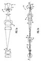
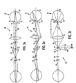
- Eye viewing device 10 includes an illumination system, the operation of which is described mainly with reference to Fig. 1A, and an imaging system, the operation of which is described mainly with reference to Fig. 1B.
- the device of Figs 1A-1E is especially well suited for use in viewing a retina through an undilated pupil.
- Small diameter undilated pupils present numerous challenges to viewing retinal images. Small diameter undilated pupils tend to inhibit the transmission of both incident light directed toward a retina and reflected light corresponding to a retinal image. Furthermore, light that is directed into a pupil and that is blocked from entry into a pupil by highly reflective surfaces of outer eye structures such as the iris and sclera tends to be reflected into a viewing system as glare.
- the device of Figs. 1A through 1E includes features which operate in combination to overcome the numerous challenges to viewing a retinal image through an undilated pupil.
- the device of Figs.1A through 1E includes the combination of a converging light source illumination system and an aperture stop.
- the converging light source illumination system operates to direct a substantial amount of light through a small diameter opening while the aperture stop operates to block glare attributable to light rays being reflected from outer eye structures.
- the illumination system operates to generate illumination light rays which converge at an apex 34 and diverge thereafter.
- An eye viewing device having a converging light ray illumination system is positioned in an operative position relative to a patient when substantially a maximum amount of incident light enters eye 11 through pupil 12.
- an operative position is achieved when apex 34 of the cone of light generated by the illumination system is positioned at about a pupil 12 of a patient.
- a converging light ray illumination system can be provided by the combination of a light source 14 and objective lens 16 positioned forward of the light source 14 for converging light rays emanating from source 14.
- a converging light source illumination system With a converging light source illumination system, a much higher percentage of incident light rays enter pupil 12 to illuminate retina 19 than are reflected off outer eye structures 17 and 21. Because there is little wasted incident light, a converging light ray illumination system reduces the electrical input power consumption of the illumination system. Because a relatively smaller amount of incident light reflects off outer eye structures such as iris 17 and sclera 21, there is less unwanted light received by the imaging system.
- Light source 14 can be a light generating light source, such as a filament-based lamp, an arc lamp, a fiber optic light source or a solid state light source.
- a preferred light source for the eye viewing device is the light source described with reference to Fig. 2.
- light source 14 is provided by a reflective element such as a mirror, which operates in association with a light-generating light source 18, such as a lamp, and a condenser lens 20 which converges light from light source 18 onto mirror 14.
- the imaging system of the device includes objective lens 16, imaging lens 22, and an eyepiece lens 24.
- a retinal image focal plane 26 is produced intermediate objective lens 16 and imaging lens 22, while an eyepiece focal plane 28 is produced intermediate imaging lens 22 and eyepiece lens 24.
- the imaging system further includes an imaging axis 30 on which lenses 16, 22, and 24 are substantially centered.
- the term "lens" can refer to a single optical element or a plurality of optical elements functioning together, while an operative position has been defined herein as the position at which substantially a maximum amount of incident light rays enter eye 11 through pupil 12.
- An operative position can also be defined as the position at which a patient's pupil is conjugate to aperture stop 32.
- the retinal image light rays crossing retinal focal plane 26 consist of light rays that enter eye 11 through pupil 12 and which are reflected from retina 19 through pupil 12. Since small undilated pupils tend to inhibit the transmission of both incident light into an eye and reflected retinal image light out of the eye, retinal images viewed through undilated pupils are readily obscured by glare (which is especially prevalent when retinas are viewed through undilated pupils since incident light is more likely to be reflected from highly reflective outer eye structures).
- retinal images can be obscured by glare attributable to other sources such as light that is reflected from a patient's cornea (corneal glare) and light that is reflected from a component of the eye viewing device such as a lens of the device (internal glare).
- device 10 includes features which operate to reduce such glare, and in so doing reduce the percentage of received light rays not corresponding to a retinal image relative to the percentage of received light rays corresponding to a retinal image.
- One feature which operates to reduce the percentage of light rays not corresponding to the retinal image is the feature of converging light illumination, described above.
- a converging light illumination system a relatively high percentage of light enters eye 11 through pupil 12, and a relatively low percentage of light is reflected from outer eye structures 17 and 21 as seen in Fig. 1A.
- Other features which may be incorporated to increase the percentage of retinal image forming received light relative to unwanted light are described hereinbelow.
- an aperture stop 32 is positioned forward of imaging lens 22 to block unwanted light.
- Aperture stop 32 should be positioned substantially coaxially with imaging axis 30 and substantially conjugate to a patient's pupil 12 when in an operative position in relation to device 10. Positioning of aperture stop 32 substantially coaxial with imaging axis 30 encourages substantially a maximum amount of useful receive imaging light to be admitted through imaging lens 22 without also admitting glare light that originates radially outside the patient's pupil 12. By positioning aperture stop 32 so that it is substantially conjugate to a pupil, aperture stop 32 operates to block light reflected from outer eye structures 17 and 21.
- the preferred position of aperture stop 32 in a device made in accordance with Figs.1A-1E can be described as one that is substantially conjugate to the apex of the cone of light generated by the illumination system.
- aperture 33 of aperture stop 32 should be sized in accordance with the diameter of the pupil through which a retina is viewed.
- the diameter of an undilated pupil is about 2mm.
- aperture 33 should be sized to correspond to a patient pupil diameter of about 2mm.
- the resulting diameter of aperture 33 is determined by multiplying the pupil diameter by the magnification of the pupil in the plane of the aperture stop 32. This same principle can be applied to optimize the instrument design for other pupil sizes, larger and smaller.
- aperture stop 32 reduces glare and improves image quality prior to the device being moved into an operative position.
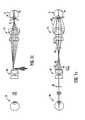
- Figs. 1C and 1D illustrate illumination light rays exiting the device and reflecting off the eye as they are received in a viewing system of device 10 during entry of the device into an eye (during the process of moving the device into an operative position).
- Fig. 1C illustrates incident light rays generated by device 10 when the device is at a distance away from an operative position
- Fig. 1D illustrates received reflected light rays of a device positioned at the same distance away from an operative position as is shown in Fig. 1C.
- light source 14 may be positioned just forward of aperture stop 32 outside of the boundary between received and blocked light and off-axis with respect to imaging axis 30 of device 10. Positioning light source forward of aperture stop 32, outside of the boundary between received and blocked light defined by aperture 33, assures that light source 14 has no obscuring effect on the viewed image and assures maximum image brightness in the user's eye. Positioning light source 14 off-axis also reduces both internal and corneal glare. By positioning light source off-axis, incident light that is reflected off of lens 16 or off of cornea 15 is directed at an angle with respect to axis 30 and, therefore, away from the optical receive path.
- Glare may be further reduced by shaping the first surface 23 of objective lens 16 so that first surface 23 is curved and substantially concentric with the center of aperture 33 as seen by the embodiment of Fig. 1E. This assures that light that is reflected from surface 23 is reflected to a point equal to and opposite light source 14 with respect to imaging axis 30. If light source 14 is positioned outside of the boundary dividing blocked and received light defined by aperture 33, the concentric curved first surface 23 assures that internal glare resulting from light being reflected from surface 23 is blocked by aperture stop 32.
- glare can be reduced by disposing linear polarizers in the imaging and illumination paths in a crossed configuration.
- light source 14 is disposed directly in the field of view in a highly defocused position in relation to focal planes 26 and 28.
- light source 14 By disposing light source 14 on imaging axis 30, light source 14 provides for maximally efficient illumination of a retina 19.
- Positioning the light source off-axis as is shown by light source 14' results in less-than-maximally efficient retinal illumination, but also reduces glare for reasons that have been discussed herein.
- Light source 14 in the embodiment of Fig. 3A-3C should be positioned in a highly defocused position in relation to any image plane of the eye viewing device conjugate to a patient's retina 19 in an operative position in relation to device 10.
- a highly defocused position for source 14 in relation to an image focal plane conjugate to a retina is provided by disposing source 14 intermediate retinal focal plane 26 and imaging lens 22.
- source 14 becomes less in focus at any plane conjugate to and including eyepiece focal plane 28 as the source is moved toward imaging lens 22 and away from retinal focal plane 26.
- source 14 is positioned as close as is physically possible to lens 22.
- Corneal glare can be reduced in the embodiment of Figs. 3A-3C if source 14 is disposed in device 10 in a position that is conjugate to the surface of a cornea when the device is in an operative position in relation to a patient. If light source 14 is positioned conjugate to cornea 15, many light rays which do happen to be reflected from cornea 15 are imaged directly onto light source 14. If light source 14 is provided by a reflective element as shown, these light rays correspond to a cornea image and are blocked before reaching eyepiece focal plane 28, thereby reducing corneal glare.
- the objective lens 16 may be provided by a lens system having a focal length of about 25mm, and a back focal length of about one-half the focal length.
- the eye viewing device may be configured so that the lens surface closest to the patient in the objective lens system is positioned about 25mm from a patient's cornea when in an operative position.
- the objective lens system accepts parallel or nearly parallel light from a patient's eye and focuses the light to an internal image located at or near the back focal plane 26 of the objective.
- the objective lens system may have a diameter of about 25mm.
- Imaging lens 22 may be provided by a lens system having a focal length of about 25mm, a back focal length of about 18mm and a clear aperture of about 20mm.
- the imaging lens may project an internal image from the objective focal plane 26 to eyepiece focal plane 28 at a magnification of about 0.6X.
- Eyepiece focal plane 28 may have an aperture of about 8mm in diameter, corresponding to the focal plane diameter of a typical 20X eyepiece.
- the axial length from objective lens 16 to eyepiece focal plane 28 may be about 160mm.
- condenser lens 20 may be provided by a condenser system having a numerical aperture of about 0.2 to 0.4, working at a magnification of about 1X to 2X, with a focal length of about 9mm.
- aperture stop 32 may be positioned substantially normal to axis 30 and approximately halfway between the moat rearward point of light source 14 and the moat forward point of imaging lens 22.
- Aperture stop 32 may have an aperture diameter of about 4.6mm.
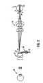
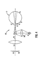
- FIG. 4 shows a comparative device.
- light source 14 is disposed forward of objective lens 16 and imaging lens 22 is deleted.
- Light source 14 is disposed in a highly defocused position in relation to retinal focal plane 26 by disposing light source 14 in proximity with objective lens 16.
- objective lens 16 does not form part of the optical illumination system. Instead, illumination light rays which converge at a cornea 15 and diverge toward a retina 19 are formed by disposing condenser lens 20 in relationship with light source mirror 14 such that light rays reflected from the mirror converge after being reflected.
- eyepiece lens 24 may optionally be removed and replaced with image sensor 52, such as a CCD image sensor, which is positioned on retinal focal plane 26.
- image sensor 52 such as a CCD image sensor
- a processor system in communication with sensor 52, can be configured to capture image signals generated by sensor 52, process such signals, and if desirable, electronically reverse or magnify any captured images to accomplish the function provided optically by imaging lens 22 of the eye viewing device of Figs 1A-3C.
- optical elements such as diffractive lenses, binary gratings, phase filters, holographic optical elements (HOE), gradient-index lenses, and hybrid optical elements.
- a binocular eye viewing device typically includes a collimating optical element 70 for collimating light rays of the imaging path, and separating optics 72 for splitting light rays transmitted by collimating optics 70 into two separate imaging paths 74A and 74B.
- Separating optics 72 typically include a combination of such optical elements as prisms and/or mirrors.
- binocular eye viewing device 10" may further include orientation optics 76 disposed in each binocular imaging path 74A, 74B for setting the orientation of images transmitted by separating optics as is necessary.
- Orientation optics 76 may include such optical elements as prism and/or mirror optical elements.
- Binocular eye viewing device 10" may further include decollimation optics 78 and eyepiece optics 80 disposed in each imaging path 74A and 74B.
- Each eyepiece optics 80 collimates light so that images can be perceived by a viewer.
- the eye tubes (not shown) of eyepiece optics 80 may be arranged in an orientation slightly diverging toward a viewer's eyes to approximate the direct viewing condition of a target by a pair of eyes.
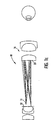
- FIG. 6 Shown in Fig. 6 is a physical schematic diagram of an embodiment of the invention which can be reconfigured for optimizing various functional aspects of the eye viewing device.
- housing 44 of eye viewing device 10 includes lens holders 60, 61, 62 and 66 and replaceable lens modules 40, 41, 42 and 46 replaceably received in their respective holders.
- replacing a certain lens module or a grouping of lens modules changes functional aspects of the eye viewing device enabling the ophthalmoscope to be optimized for a specific intended use.
- the area of retina 19 that is illuminated by the illumination system depends on the diameter and optical power of objective lens 16 and on the magnification selected for the lens at the operative position of the eye viewing device. This area corresponds to the angle ⁇ as shown in Figs. 1A and 3C.
- the field of view of the imaging system meanwhile, also depends on the diameter and optical power of objective lens 16 and on the magnification of the lens at the operative position of the eye viewing device.
- eye viewing device 10 images a wide field of view. While a wide field of view and illumination angle, ⁇ , are highly desirable for an accurate and efficient diagnosis of various problems, a smaller field of view and illumination angle are desirable for ease of use. As the angle of illumination, ⁇ , becomes less steep, illumination light rays are more easily directed into an eye through a pupil, so that entry into an eye is easier. This is because as the illumination angle, ⁇ , becomes less steep, light rays from source 14 can be directed through pupil 12 over a greater range of cornea-to-lens distances. Accordingly, in view of the above, it would be beneficial to provide an eye viewing device which could be configured either for optimized field of view or optimized ease of use.
- the imaging system of device 10 images a field that contains the area of a retina that is illuminated by the illumination system. Most preferably the area of the retina that is imaged by the imaging system is about 15 percent to 30 percent larger than the area that is illuminated. This feature provides improved orientation of a viewed field and reduces alignment considerations between illumination and viewing.
- FIG. 6 A possible embodiment of reconfigurable eye viewing device according to the invention is described with reference to the physical schematic diagram of Fig. 6.
- This particular physical layout diagram includes first and second lens modules 40 and 41.
- First lens module 40 includes objective lens 16
- second lens module 41 includes imaging lens 22. While the field of view and illumination angle depend mainly on the sizing, optical power, and magnification selected for objective lens 16, imaging lens 22 will normally be replaced along with lens 16, since the sizing and optical power of lens 16 are coordinated with those of lens 22.
- the housing 44 and lens modules 40, 41 are complementarily designed so that the modular lens modules can be manually removed and replaced from housing 44 while maintaining a common eyepiece focal plane 28.
- a first set of lens modules can be provided to configure the eye viewing device for imaging a wide field of view, while a second set of modules can provide a reduced field of view (but with increased magnification), making the instrument easier to maneuver into an operative position.
- a second set of modules can provide a reduced field of view (but with increased magnification), making the instrument easier to maneuver into an operative position.
- Such a device can be made easier to use simply by replacing the first set of lens modules with the second set of lens modules.
- the illumination condenser system may also be changed in a modular fashion to optimize the illumination characteristics to suit the user's needs.
- the ability to collect the light from a light generating light source is balanced with the angle at which the light can be transmitted and the magnification at which the image of the light generating light source is projected.
- the lenses inside the illumination lens module 42 can be selected such that the illumination system matches the illumination numerical aperture of the given objective module 40.
- the invention can be adapted to capture electronic images representing an imaged retina.
- an eye viewing device 10 is shown that can be reconfigured for electronic image capture.
- Fig. 6 shows an eye viewing device adapted so that eyepiece module 46 can be replaced with a video module 50.
- eye viewing device 10 normally includes an eyepiece module 46 having an eyepiece lens 24 which collimates imaging light rays so that a retinal image can be viewed by a user.
- Eyepiece 46 can be replaced with video module 50 which includes certain components that configure the eye viewing device for video capture.
- a video module 50 may contain an image sensor 52, such as a CCD image sensor, which is in an operative position in relation to the imaging system when the video module is installed in holder 66.
- the image sensor 52 is in electrical communication with a processor system 54 which may be programmed to control image sensor 52 and to capture and, possibly to store image data generated by and received from image sensor 52. While processor system 54 is shown as being disposed in video module 50, it is understood that processor system 54 could be disposed external to video module 50.
- the video module 50 may further be in communication with an external display screen and/or an external processing system via cable 56, for example, so that video images captured by image sensor can be displayed or otherwise output, and possibly archived.
- Video module 50 can be designed so that image sensor 52 lies on eyepiece focal plane 28 when module 50 is in an operative position in holder 66. It is seen that an eye viewing device of the invention can be configured for video capture by replacing eyepiece module 46 with a video module 50 without adding or replacing additional lenses of the imaging system. Alternative sized imagera may also be used, with the addition of image resizing lenses. Such a configuration shifts the location of focal plane 28.
Abstract
Description
wherein said imaging system has at least one retinal image focal plane (26); and
the illumination system includes a light source (14) disposed in said imaging axis (30) which is positioned in a defocused position in relation to said at least one retinal image focal plane (26) wherein said illumination system is adapted to generate illumination light rays that converge substantially at or forward of said patient end,. whereby said converged light rays can easily enter a pupil (12) arranged forward of said patient end.
Claims (26)
- An eye viewing device (10) for viewing a structure (19) of an eye (11) having a pupil (12), said device (10) comprising:characterised in that the aperture stop (32) is sized to substantially correspond to a size of said pupil (12) whereby corneal glare is reduced.an illumination system generating a converging cone of light that converges at an apex (34) and diverges thereafter;an imaging system having an imaging axis (30); andan aperture stop (32) disposed in said device (10) substantially coaxial with said imaging axis (30) and substantially conjugate to said apex (34);
- A device (10) according to claim 1 wherein said structure (19) is a retina.
- A device (10) according to claim 1 or 2 wherein an aperture (33) of said aperture stop (32) is sized to substantially correspond to a size of said pupil (12) when said pupil (12) is undilated.
- A device (10) according to claim 1, 2 or 3 wherein said illumination system includes a light source (14) positioned off-axis with respect to said imaging axis (30), whereby internal and corneal glare in said device (10) is reduced.
- A device (10) according to claim 4 wherein said imaging system includes an objective lens (16), said objective lens (16) having a first surface (23) closest to said light source (14) curved substantially concentric about a center of an aperture (33) of said aperture stop (32), whereby internal glare in said device (10) is reduced.
- A device (10) according to claim 4 or 5 wherein said off-axis positioned light source (14) is positioned outside of an aperture (33) of said aperture stop (32), whereby said light source (14) has no obscuring effect on images received by said viewing device (10).
- A device (10) according to any of the preceding claims wherein said imaging system includes an image sensor (52) for generating electrical signals representing said structure (19).
- A device (10) according to any of the preceding claims wherein said device (10) comprises binocular optics (70, 72, 76, 78, 80) for forming a binocular image of said eye structure (19).
- A device (10) according to claim 8 wherein said binocular optics (70, 72, 76, 78, 80) include:collimating optics (70) for collimating light along said imaging axis (30);separating optics (72) for separating light transmitted by said collimating optics along first and second light paths (74a, 74b);orientation optics (76) disposed in at least one of said first and second paths (74a, 74b) for setting an orientation of received images;decollimating optics (78) disposed in at least one of said first and second optical paths (74a, 74b) for decollimating light transmitted by said orientation optics (76); andeyepiece optics (80) disposed in at least one of said first and second paths (74a, 74b) for recollimating light decollimated by said decollimating optics (78).
- A device (10) according to any preceding claim wherein a retinal field of view of said imaging system is larger than a retinal area of illumination of said illumination system.
- A device (10) according to any preceding claim wherein a retinal field of view of said imaging system is between about 15 to 30 percent larger than a retinal area of illumination of said illumination system.
- A device (10) according to any preceding claim wherein said device (10) includes a housing (44) including at least one lens holder (60, 61, 62, 66), and a plurality of lenses (16, 20, 22, 24), at least one of said lenses (16, 20, 22, 24) being packaged in a lens module (40, 41, 42, 46) which is adapted to be received in said at least one lens holder (60, 61, 62, 66).
- A device (10) according to any of claims 1 to 11 wherein said device (10) includes a housing (44) and wherein said device (10) further comprises:an eyepiece holder (66) defined by said housing (44);an eyepiece (46) having an eyepiece lens (24), said eyepiece (46) being adapted to be received in said eyepiece holder (66); anda video module (50) having an image sensor (52), said video module (50) being adapted to be received in said eyepiece holder (66) wherein said eyepiece holder (66) is adapted to receive only one of said eyepiece (46) or said video module (50) at a given time.
- A device (10) according to any preceding claim wherein said illumination system and said imaging system include a common objective lens (16).
- A device (10) according to any of claims 1 to 11 comprising
a housing (44);
an objective lens holder (60) for receiving an objective lens module (40);
an imaging lens holder (61) for receiving an imaging lens module (41);
a first objective lens module and imaging lens module pair configured to provide wide field viewing; and
a second objective lens (16) module and imaging lens module pair configured to provide narrower field viewing and easier entry than said first objective lens (16) module and imaging lens module pair, wherein said objective lens (16) and imaging lens module holders are adapted to receive only one of said first or second objective lens (16) and imaging lens modules at a given time. - A device (10) according to any of claims 2 to 15 having a patient end and a viewing end, and
wherein said imaging system has at least one retinal image focal plane (26); and
the illumination system includes a light source (14) disposed in said imaging axis (30) which is positioned in a defocused position in relation to said at least one retinal image focal plane (26) wherein said illumination system is adapted to generate illumination light rays that converge substantially at or forward of said patient end, whereby said converged light rays can easily enter a pupil (12) arranged forward of said patient end. - A device (10) according to claim 16 wherein said illumination system including an objective lens (16) disposed intermediate said light source (14) and said patient end, said light source (14) positioned beyond said retinal image focal plane (26) in a direction away from said objective lens (16) so that said objective lens (16) operates to converge illumination light rays generated by said light source (14).
- A device (10) according to claim 16 or 17 wherein said light source (14) comprises a reflective element.
- A device (10) according to any of claims 16 to 18 wherein said light source (14) comprises a light-generating light source (18).
- A device (10) according to claim 16 or 17 wherein said illumination system comprises:a light-generating light source (18) directing light toward said reflective element (14); anda condenser optical element (20) interposed between said light-generating light source (18) and said reflective element (14), said condenser optical element (20) converging light rays from said light-generating light source (18) onto said reflective element (14).
- A device (10) according to claim 19 or 20 wherein said light source (14) is provided by a miniature incandescent lamp.
- A device (10) according to claim 16 wherein said imaging system includes an objective optical element (16) and an imaging optical element (22), and wherein said light source (14) is disposed intermediate said objective optical element (16) and said imaging optical element (22).
- A device (10) according to claim 22 wherein said light source (14) is disposed in close proximity with said imaging optical element (22).
- A device (10) according to claim 16 or 17 wherein said light source (14) is a light transmitting light source selected from the group consisting of a light pipe, a light guide, a diffractive optical element and a holographic optical element.
- A device (10) according to any of claims 16 to 24 wherein said light source (14) is disposed in a position that is substantially conjugate with patient's cornea (15) when said device (10) is in an operative position in relation to said eye (11), so that light rays reflected from said cornea (15) are converged onto said light source (14).
- A device (10) according to any preceding claim wherein said illumination and imaging systems do not comprise a beam-splitter.
Applications Claiming Priority (6)
| Application Number | Priority Date | Filing Date | Title |
|---|---|---|---|
| US09/198,545 US6065837A (en) | 1998-11-24 | 1998-11-24 | Ophthalmoscope comprising defocused light source |
| US198545 | 1998-11-24 | ||
| US28130099A | 1999-11-22 | 1999-11-22 | |
| US09/444,161 US6409341B1 (en) | 1998-11-24 | 1999-11-22 | Eye viewing device for retinal viewing through undilated pupil |
| US444161 | 1999-11-22 | ||
| PCT/US1999/027857 WO2000030527A1 (en) | 1998-11-24 | 1999-11-23 | Eye viewing device for retinal viewing through undilated pupil |
Publications (2)
| Publication Number | Publication Date |
|---|---|
| EP1152687A1 EP1152687A1 (en) | 2001-11-14 |
| EP1152687B1 true EP1152687B1 (en) | 2004-09-01 |
Family
ID=26893894
Family Applications (1)
| Application Number | Title | Priority Date | Filing Date |
|---|---|---|---|
| EP99959085A Expired - Lifetime EP1152687B1 (en) | 1998-11-24 | 1999-11-23 | Eye viewing device for retinal viewing through undilated pupil |
Country Status (9)
| Country | Link |
|---|---|
| US (2) | US6527390B2 (en) |
| EP (1) | EP1152687B1 (en) |
| JP (1) | JP3905312B2 (en) |
| CN (1) | CN1157153C (en) |
| AT (1) | ATE274833T1 (en) |
| AU (1) | AU768276B2 (en) |
| CA (1) | CA2352148C (en) |
| DE (1) | DE69919902T2 (en) |
| WO (1) | WO2000030527A1 (en) |
Cited By (4)
| Publication number | Priority date | Publication date | Assignee | Title |
|---|---|---|---|---|
| US7784940B2 (en) | 1998-11-24 | 2010-08-31 | Welch Allyn, Inc. | Eye viewing device comprising video capture optics |
| US8944596B2 (en) | 2011-11-09 | 2015-02-03 | Welch Allyn, Inc. | Digital-based medical devices |
| US10078226B2 (en) | 2013-10-14 | 2018-09-18 | Welch Allyn, Inc. | Portable eye viewing device enabled for enhanced field of view |
| US11147441B2 (en) | 2018-01-16 | 2021-10-19 | Welch Allyn, Inc. | Physical assessment device |
Families Citing this family (29)
| Publication number | Priority date | Publication date | Assignee | Title |
|---|---|---|---|---|
| US6718103B2 (en) * | 2000-04-17 | 2004-04-06 | Vertical Computer Systems, Inc. | Apparatus and method for transmitting images over a single-filament fiber optic cable |
| CN1447146A (en) * | 2002-03-26 | 2003-10-08 | 株式会社拓普康 | Operation microscope |
| GB2387663B (en) * | 2002-04-17 | 2005-10-12 | Roger Hanif Armour | Ophthalmoscope |
| JP3931139B2 (en) * | 2002-12-27 | 2007-06-13 | 興和株式会社 | Ophthalmic imaging equipment |
| JP4047217B2 (en) * | 2003-05-01 | 2008-02-13 | キヤノン株式会社 | Ophthalmic equipment |
| AU2003903157A0 (en) * | 2003-06-20 | 2003-07-03 | The Lions Eye Institute of Western Australia Incorporated The | Ophthalmic camera and ophthalmic camera adaptor |
| DE10347732B4 (en) * | 2003-10-14 | 2019-10-17 | Carl Zeiss Meditec Ag | Lighting device and surgical microscope and their use |
| GB0324526D0 (en) * | 2003-10-21 | 2003-11-26 | Armour Roger H | Ophthalmoscope |
| DE602004020505D1 (en) * | 2003-10-28 | 2009-05-20 | Welch Allyn Inc | DIGITAL DOCUMENT OPHTHALMOSCOPE |
| US7708403B2 (en) | 2003-10-30 | 2010-05-04 | Welch Allyn, Inc. | Apparatus and method for diagnosis of optically identifiable ophthalmic conditions |
| US7338167B2 (en) | 2003-12-10 | 2008-03-04 | Joslin Diabetes Center, Inc. | Retinal imaging system |
| US20050285056A1 (en) * | 2004-06-11 | 2005-12-29 | Smith Adlai H | Process for manufacture of semiconductor chips utilizing a posteriori corrections to machine control system and settings |
| US20070156021A1 (en) * | 2005-09-14 | 2007-07-05 | Bradford Morse | Remote imaging apparatus having an adaptive lens |
| US8027095B2 (en) * | 2005-10-11 | 2011-09-27 | Hand Held Products, Inc. | Control systems for adaptive lens |
| US20080145127A1 (en) * | 2006-10-10 | 2008-06-19 | Hang Yu Liu | Book-shaped, back-typing, ergonomic computer keyboard |
| DE102009024942A1 (en) * | 2009-06-09 | 2010-12-23 | Carl Zeiss Surgical Gmbh | Light source arrangement for a lighting device of a medical-optical observation device |
| US8786210B2 (en) | 2010-06-30 | 2014-07-22 | Welch Allyn, Inc. | Drive circuit for light emitting diode |
| FI126159B (en) * | 2010-09-22 | 2016-07-29 | Optomed Oy | survey Instruments |
| CN102525404B (en) * | 2010-11-05 | 2015-09-30 | 尼德克株式会社 | Ophthalmoligic instrument |
| DE102011085527B4 (en) * | 2011-10-31 | 2019-01-17 | Leica Microsystems (Schweiz) Ag | Illumination device for a stereomicroscope, in particular a surgical microscope |
| US9060718B2 (en) | 2012-02-13 | 2015-06-23 | Massachusetts Institute Of Technology | Methods and apparatus for retinal imaging |
| US9179840B2 (en) * | 2012-03-17 | 2015-11-10 | Visunex Medical Systems Co. Ltd. | Imaging and lighting optics of a contact eye camera |
| FI125445B (en) * | 2012-09-12 | 2015-10-15 | Trividi Oy | Blick Control Device |
| CN104523221A (en) * | 2014-12-17 | 2015-04-22 | 严俊文 | Eye ground camera imaging system based on liquid lens focusing |
| JP6862086B2 (en) * | 2015-12-02 | 2021-04-21 | 興和株式会社 | Eye device |
| US10585291B2 (en) * | 2017-04-28 | 2020-03-10 | Yonatan Gerlitz | Eye safety system for lasers |
| JP6874832B2 (en) * | 2017-04-28 | 2021-05-19 | 株式会社ニコン | Ophthalmic imaging optical system, ophthalmic imaging device, ophthalmic image acquisition method and ophthalmic image system |
| US11202567B2 (en) * | 2018-07-16 | 2021-12-21 | Verily Life Sciences Llc | Retinal camera with light baffle and dynamic illuminator for expanding eyebox |
| CN115845269B (en) * | 2022-12-19 | 2024-04-02 | 光朗(海南)生物科技有限责任公司 | Illumination physiotherapy device for eyes |
Family Cites Families (108)
| Publication number | Priority date | Publication date | Assignee | Title |
|---|---|---|---|---|
| US3586424A (en) * | 1968-09-13 | 1971-06-22 | American Optical Corp | Monocular indirect ophthalmoscope |
| US3638641A (en) | 1969-11-19 | 1972-02-01 | Arcoa Inc | Multiphasic medical examinations screening laboratory construction |
| US3600098A (en) * | 1969-12-29 | 1971-08-17 | Bausch & Lomb | Optical alignment method and apparatus |
| US3614214A (en) | 1970-09-09 | 1971-10-19 | Stanford Research Inst | Method and system for taking photographs of an eye fundus |
| US3698099A (en) | 1971-01-29 | 1972-10-17 | American Optical Corp | Ophthalmoscopes |
| JPS5225252B2 (en) | 1972-09-16 | 1977-07-06 | ||
| US3944341A (en) | 1972-09-25 | 1976-03-16 | Retina Foundation | Wide-angle ophthalmoscope and fundus camera |
| US4265519A (en) | 1972-09-25 | 1981-05-05 | Retina Foundation | Wide-angle ophthalmoscope |
| JPS49136227U (en) | 1973-03-22 | 1974-11-22 | ||
| JPS5713294B2 (en) | 1973-03-31 | 1982-03-16 | ||
| US3893447A (en) | 1973-06-04 | 1975-07-08 | Univ Johns Hopkins | Simultaneous angiography of the separate retinal and choroidal circulations |
| US4023189A (en) | 1974-03-29 | 1977-05-10 | Varian Associates | Wide angle fundus illumination and photography apparatus |
| JPS5343277B2 (en) | 1974-06-19 | 1978-11-17 | ||
| US3915564A (en) | 1974-09-12 | 1975-10-28 | Zeiss Stiftung | Retinal image-display system |
| US4135791A (en) | 1974-12-02 | 1979-01-23 | Varian Associates, Inc. | Reduced glare scanner |
| US4026638A (en) | 1974-12-02 | 1977-05-31 | Varian Associates | Reduced glare scanner |
| US4068932A (en) | 1975-05-23 | 1978-01-17 | Canon Kabushiki Kaisha | Optical instrument for examining the eye fundus |
| US4102563A (en) | 1975-12-01 | 1978-07-25 | Canon Kabushiki Kaisha | Eye fundus camera free from undesired reflected and diffused light beams |
| JPS6057853B2 (en) | 1975-12-08 | 1985-12-17 | キヤノン株式会社 | fundus camera |
| JPS5282246A (en) | 1975-12-27 | 1977-07-09 | Olympus Optical Co Ltd | Light source device |
| JPS52108123A (en) | 1976-03-09 | 1977-09-10 | Canon Inc | Ophthalmofundus camera |
| US4198144A (en) | 1976-04-01 | 1980-04-15 | Canon Kabushiki Kaisha | Eye fundus camera |
| US4201456A (en) | 1976-04-22 | 1980-05-06 | Wolbarsht Myron L | Method and apparatus for detecting the focusing condition of an optical system |
| JPS52141094A (en) | 1976-05-19 | 1977-11-25 | Canon Kk | Dental wide angle objective lens |
| JPS52150645A (en) | 1976-06-09 | 1977-12-14 | Canon Inc | Objective lens for opthalmology |
| US4095379A (en) | 1976-07-19 | 1978-06-20 | Joel Weintraub | Multi-examining space arrangement for a rotatable ophthalmic table or the like |
| US4196979A (en) | 1976-10-16 | 1980-04-08 | Canon Kabushiki Kaisha | Method and device for detecting distance between eye-examining instrument and eye |
| US4187014A (en) | 1977-01-29 | 1980-02-05 | Tokyo Kogaku Kikai Kabushiki Kaisha | Eye fundus camera |
| JPS5843090B2 (en) * | 1977-04-12 | 1983-09-24 | キヤノン株式会社 | Ophthalmological device with adjustment system |
| US4253743A (en) | 1977-05-17 | 1981-03-03 | Canon Kabushiki Kaisha | Eye testing instrument |
| JPS53144192A (en) | 1977-05-19 | 1978-12-15 | Canon Kk | Ophthalmolgic decice |
| JPS53144193A (en) | 1977-05-20 | 1978-12-15 | Canon Kk | Ophthalmologic machine having operating distance detector |
| JPS5412194A (en) | 1977-06-29 | 1979-01-29 | Canon Kk | Ophthalmologic instrument |
| US4265518A (en) | 1977-06-30 | 1981-05-05 | Canon Kabushiki Kaisha | Variable magnification apparatus having illumination compensating ability |
| JPS5418190A (en) | 1977-07-11 | 1979-02-09 | Canon Kk | Eyeeground observing camera |
| JPS5430695A (en) | 1977-08-09 | 1979-03-07 | Canon Kk | Variable angular ophthalmologic device |
| DE2741992C3 (en) | 1977-09-17 | 1980-10-30 | Fa. Carl Zeiss, 7920 Heidenheim | Ophthalmological device for examination and photographic fundus |
| DE2843287A1 (en) | 1977-10-05 | 1979-04-19 | Canon Kk | EYE EXAMINATION INSTRUMENT |
| DE2744707C3 (en) | 1977-10-05 | 1980-07-24 | Fa. Carl Zeiss, 7920 Heidenheim | Ophthalmological device for stereoscopic examination and photographic fundus |
| JPS6054053B2 (en) | 1977-11-15 | 1985-11-28 | ミノルタ株式会社 | Fundus camera for easy pupil alignment |
| JPS5491997A (en) | 1977-12-28 | 1979-07-20 | Nippon Chemical Ind | Optical system for correcting visual power with internal focus |
| US4184752A (en) | 1978-04-07 | 1980-01-22 | American Optical Corporation | Instrument illuminator |
| DE2915639C2 (en) | 1978-04-19 | 1988-06-16 | Canon K.K., Tokio/Tokyo | Eye examination device for examining the fundus |
| JPS54141095A (en) | 1978-04-25 | 1979-11-01 | Canon Kk | Ophthalmologic camera |
| US4235540A (en) | 1978-05-10 | 1980-11-25 | Tokyo Kogaku Kikai Kabushiki Kaisha | Eye fundus camera having variable power photographing optical system |
| JPS54147690A (en) | 1978-05-12 | 1979-11-19 | Minolta Camera Kk | Eyeground photometry optical system |
| JPS6051094B2 (en) | 1978-08-15 | 1985-11-12 | キヤノン株式会社 | Optical system with movable focusing lens group |
| US4238142A (en) | 1978-12-18 | 1980-12-09 | American Optical Corporation | Method and apparatus for examining and photographing the ocular fundus |
| US4257691A (en) | 1979-01-05 | 1981-03-24 | Brooks Philip A | Line of sight display apparatus |
| JPS55101241A (en) | 1979-01-30 | 1980-08-01 | Tokyo Optical | Eyeground camera equipped with operation distance detector |
| JPS55106137A (en) | 1979-02-09 | 1980-08-14 | Tokyo Optical | Counter photographing apparatus in fluorescence photograph eyeground camera |
| JPS55133239A (en) | 1979-04-05 | 1980-10-16 | Olympus Optical Co | Microscope for blood vessel |
| US4249825A (en) | 1979-05-14 | 1981-02-10 | The Trustees Of Boston University | Method and apparatus suitable for ocular blood flow analysis |
| JPS565637A (en) | 1979-06-28 | 1981-01-21 | Tokyo Optical | Operation distance detector in ophthalmology machine |
| JPS5631732A (en) | 1979-08-24 | 1981-03-31 | Canon Kk | Automatic focus adjusting camera |
| GB2061546B (en) | 1979-09-13 | 1983-06-29 | Konan Camera Res Inst | Adaptor for use with ophthalmological microscope |
| JPS5691729A (en) | 1979-12-25 | 1981-07-24 | Nippon Chemical Ind | Optical system for examinating and photographing eyeground |
| JPS56132936A (en) | 1980-03-21 | 1981-10-17 | Tokyo Optical | Eye bottom camera |
| JPS56148337A (en) | 1980-04-22 | 1981-11-17 | Olympus Optical Co | Eye bottom camera |
| JPS56151929A (en) | 1980-04-25 | 1981-11-25 | Canon Inc | Fundus camera |
| JPS56166832A (en) | 1980-05-08 | 1981-12-22 | Olympus Optical Co | Optical system of ophthalmic machine |
| JPS573622A (en) | 1980-06-10 | 1982-01-09 | Tokyo Optical | Apparatus for detecting operation distance in ophthalmology |
| US4712894A (en) | 1980-09-24 | 1987-12-15 | Tokyo Kogaku Kikai Kabushiki Kaisha | Ophthalmoscopic instrument having working position detecting means |
| JPS5772625A (en) | 1980-09-24 | 1982-05-07 | Tokyo Optical | Ophthalmology machine equipped with apparatus for automatically detecting correct position of eye to be inspected |
| JPS5784036A (en) | 1980-11-14 | 1982-05-26 | Tokyo Optical | Apparatus for detecting correct position in ophthalmic machine |
| JPS57125732A (en) | 1981-01-29 | 1982-08-05 | Tokyo Optical | Apparatus for detecting focus position in ophthalmic machine |
| US4799783A (en) | 1981-03-09 | 1989-01-24 | Canon Kabushiki Kaisha | Eye fundus camera |
| JPS57160430A (en) | 1981-03-27 | 1982-10-02 | Nippon Kogaku Kk | Apparatus for observing eye bottom |
| US4469416A (en) | 1981-04-24 | 1984-09-04 | Tokyo Kogaku Kikai Kabushiki Kaisha | Automatic focusing means for an ophthalmoscopic instrument |
| JPS57200126A (en) | 1981-06-04 | 1982-12-08 | Nippon Kogaku Kk | Self-knowledge eye refractive force measuring apparatus |
| US4453808A (en) | 1981-06-25 | 1984-06-12 | Tokyo Kogaku Kikai Kabushiki Kaisha | Apparatus for detecting the position of a patient's eye in ophthalmologic instruments |
| US4572627A (en) | 1981-11-21 | 1986-02-25 | Canon Kabushiki Kaisha | Eye fundus camera |
| JPS58152535A (en) | 1982-03-05 | 1983-09-10 | キヤノン株式会社 | Optical apparatus having focusing function |
| US4485820A (en) | 1982-05-10 | 1984-12-04 | The Johns Hopkins University | Method and apparatus for the continuous monitoring of hemoglobin saturation in the blood of premature infants |
| US4464608A (en) | 1982-09-13 | 1984-08-07 | Warner Lambert Technologies, Inc. | Circuit for controlling optical apparatus such as an ophthalmoscope |
| JPS5949738A (en) | 1982-09-16 | 1984-03-22 | 株式会社トプコン | Photographing mode change-over apparatus of eye bottom camera |
| JPS5949737A (en) | 1982-09-16 | 1984-03-22 | 株式会社トプコン | Illumination apparatus of eye bottom camera |
| JPS5953005U (en) | 1982-09-28 | 1984-04-07 | 旭光学工業株式会社 | Illumination optical axis adjustment mechanism of ophthalmoscope with imaging device |
| US4715703A (en) | 1982-10-12 | 1987-12-29 | Rodenstock Instrument Corporation | Ocular-fundus analyzer |
| JPS59156324A (en) | 1983-02-25 | 1984-09-05 | 株式会社トプコン | Signal detector of ophthalmic machine |
| JPS59174144A (en) | 1983-03-22 | 1984-10-02 | キヤノン株式会社 | Ophthalmic photographing apparatus |
| JPS59189826A (en) | 1983-04-13 | 1984-10-27 | 株式会社トプコン | Retinal camera |
| JPS6060831A (en) | 1983-09-14 | 1985-04-08 | 株式会社トプコン | Eyeground camera |
| JPS6066725A (en) | 1983-09-20 | 1985-04-16 | 株式会社トプコン | Opthalimic photographing apparatus |
| JPS6077737A (en) | 1983-10-04 | 1985-05-02 | 株式会社トプコン | Exposure controller of ophthalmic photographing apparatus |
| DE3339172A1 (en) | 1983-10-28 | 1985-05-15 | Fa. Carl Zeiss, 7920 Heidenheim | LIGHT TRAP FOR EYE EXAMINATION DEVICES |
| JPS60137347A (en) | 1983-12-27 | 1985-07-20 | キヤノン株式会社 | Automatic exposure amount control eyeground camera |
| US4682866A (en) * | 1984-11-08 | 1987-07-28 | David Volk | Head-borne binocular indirect ophthalmoscope with integrated telescope |
| US4755043A (en) | 1985-02-15 | 1988-07-05 | Somec, Inc. | Portable scanning digital pupillometer and method of use thereof |
| US4812033A (en) | 1985-02-26 | 1989-03-14 | Canon Kabushiki Kaisha | Ophthalmic apparatus |
| US4732466A (en) | 1985-04-04 | 1988-03-22 | Humphrey Instruments, Inc. | Fundus camera |
| US4717952A (en) | 1985-06-14 | 1988-01-05 | Canon Kabushiki Kaisha | Medical television system |
| US4721378A (en) * | 1985-09-24 | 1988-01-26 | David Volk | Condensing-image forming optical system for indirect ophthalmoscopy |
| US4755044A (en) | 1986-01-06 | 1988-07-05 | Massachusetts Institute Of Technology | Remote ophthalmoscope and fundus photography unit |
| DE3608515A1 (en) * | 1986-03-14 | 1987-09-24 | Oculus Optikgeraete Gmbh | OPTIONAL DEVICE FOR MICROSCOPE |
| US4998533A (en) | 1986-07-15 | 1991-03-12 | Winkelman James W | Apparatus and method for in vivo analysis of red and white blood cell indices |
| US4991584A (en) | 1986-10-25 | 1991-02-12 | Canon Kabushiki Kaisha | Ophthalmic examining apparatus and method capable of examining glaucoma |
| JP2561828B2 (en) | 1987-01-26 | 1996-12-11 | キヤノン株式会社 | Fundus examination device |
| US4856891A (en) * | 1987-02-17 | 1989-08-15 | Eye Research Institute Of Retina Foundation | Eye fundus tracker/stabilizer |
| US4824238A (en) | 1987-05-27 | 1989-04-25 | George L. Spaeth | Comparator for optic disc analysis and method of use thereof |
| US5037194A (en) | 1988-05-31 | 1991-08-06 | Canon Kabushiki Kaisha | Ophthalmologic apparatus and method of compounding the image of an eye to be examined |
| US4927260A (en) | 1988-10-11 | 1990-05-22 | Orville Gordon | Apparatus and method for the precision evaluation of visual function in the fovea centralis (macula) area of the retina |
| JP2927445B2 (en) | 1989-04-14 | 1999-07-28 | 株式会社トプコン | Stereoscopic fundus camera |
| US5216456A (en) * | 1990-10-29 | 1993-06-01 | Volk Donald A | Optical device for use with a slit lamp biomicroscope |
| GB9323065D0 (en) * | 1993-11-09 | 1994-01-05 | Besca Ltd | A wide field retinal scanning ophthalmoscope |
| DE29601263U1 (en) * | 1996-01-25 | 1997-05-28 | Moeller J D Optik | Illumination device for a surgical microscope |
| US5873832A (en) * | 1996-08-12 | 1999-02-23 | Xeyex Corporation | Method and apparatus for measuring properties of the eye using a virtual image |
| US6151167A (en) | 1998-08-05 | 2000-11-21 | Microvision, Inc. | Scanned display with dual signal fiber transmission |
-
1999
- 1999-11-23 CN CNB998135844A patent/CN1157153C/en not_active Expired - Fee Related
- 1999-11-23 JP JP2000583418A patent/JP3905312B2/en not_active Expired - Fee Related
- 1999-11-23 WO PCT/US1999/027857 patent/WO2000030527A1/en active IP Right Grant
- 1999-11-23 DE DE69919902T patent/DE69919902T2/en not_active Expired - Lifetime
- 1999-11-23 CA CA002352148A patent/CA2352148C/en not_active Expired - Fee Related
- 1999-11-23 AU AU16331/00A patent/AU768276B2/en not_active Ceased
- 1999-11-23 EP EP99959085A patent/EP1152687B1/en not_active Expired - Lifetime
- 1999-11-23 AT AT99959085T patent/ATE274833T1/en not_active IP Right Cessation
-
2001
- 2001-12-27 US US10/033,557 patent/US6527390B2/en not_active Expired - Fee Related
-
2003
- 2003-01-07 US US10/337,588 patent/US6939006B2/en not_active Expired - Fee Related
Cited By (9)
| Publication number | Priority date | Publication date | Assignee | Title |
|---|---|---|---|---|
| US7784940B2 (en) | 1998-11-24 | 2010-08-31 | Welch Allyn, Inc. | Eye viewing device comprising video capture optics |
| US8337017B2 (en) | 1998-11-24 | 2012-12-25 | Welch Allyn, Inc. | Eye viewing device comprising video capture optics |
| US8944596B2 (en) | 2011-11-09 | 2015-02-03 | Welch Allyn, Inc. | Digital-based medical devices |
| US9642517B2 (en) | 2011-11-09 | 2017-05-09 | Welch Allyn, Inc. | Digital-based medical devices |
| US10238462B2 (en) | 2011-11-09 | 2019-03-26 | Welch Allyn, Inc. | Digital-based medical devices |
| US11553981B2 (en) | 2011-11-09 | 2023-01-17 | Welch Allyn, Inc. | Digital-based medical devices |
| US10078226B2 (en) | 2013-10-14 | 2018-09-18 | Welch Allyn, Inc. | Portable eye viewing device enabled for enhanced field of view |
| US11147441B2 (en) | 2018-01-16 | 2021-10-19 | Welch Allyn, Inc. | Physical assessment device |
| USD959661S1 (en) | 2018-01-16 | 2022-08-02 | Welch Allyn, Inc. | Medical viewing device |
Also Published As
| Publication number | Publication date |
|---|---|
| US6527390B2 (en) | 2003-03-04 |
| CN1328431A (en) | 2001-12-26 |
| AU1633100A (en) | 2000-06-13 |
| JP3905312B2 (en) | 2007-04-18 |
| DE69919902D1 (en) | 2004-10-07 |
| US6939006B2 (en) | 2005-09-06 |
| US20020089644A1 (en) | 2002-07-11 |
| CN1157153C (en) | 2004-07-14 |
| US20030098952A1 (en) | 2003-05-29 |
| WO2000030527A1 (en) | 2000-06-02 |
| CA2352148A1 (en) | 2000-06-02 |
| DE69919902T2 (en) | 2005-09-15 |
| CA2352148C (en) | 2008-01-15 |
| ATE274833T1 (en) | 2004-09-15 |
| AU768276B2 (en) | 2003-12-04 |
| WO2000030527A8 (en) | 2001-12-13 |
| EP1152687A1 (en) | 2001-11-14 |
| JP2004500139A (en) | 2004-01-08 |
Similar Documents
| Publication | Publication Date | Title |
|---|---|---|
| EP1152687B1 (en) | Eye viewing device for retinal viewing through undilated pupil | |
| US6637882B1 (en) | Eye viewing device for retinal viewing through undilated pupil | |
| AU2001263366A1 (en) | Eye viewing device comprising eyepiece and video capture optics | |
| US6409341B1 (en) | Eye viewing device for retinal viewing through undilated pupil | |
| EP1694195B1 (en) | Digital documenting ophthalmoscope | |
| JP5658371B2 (en) | Apparatus and method for imaging the eye | |
| JP3309615B2 (en) | Image observation apparatus and binocular image observation apparatus using the same | |
| US6065837A (en) | Ophthalmoscope comprising defocused light source | |
| JPH0838431A (en) | Device for eyegrounds illumination | |
| CN102458228A (en) | Ophthalmologic imaging apparatus and ophthalmologic imaging method | |
| JP2018051036A (en) | Eyeground imaging apparatus | |
| CN212781476U (en) | Be applied to ophthalmic surgery microscope's multi-wavelength multi-angle lighting device | |
| JPH0898812A (en) | Retinal camera | |
| JP2580189B2 (en) | Fundus camera | |
| JPH10314120A (en) | Fundus camera | |
| CN111665618A (en) | Multi-position stereoscopic vision multi-wavelength video ophthalmic surgery microscope | |
| JPH11290277A (en) | Fundus camera |
Legal Events
| Date | Code | Title | Description |
|---|---|---|---|
| PUAI | Public reference made under article 153(3) epc to a published international application that has entered the european phase |
Free format text: ORIGINAL CODE: 0009012 |
|
| 17P | Request for examination filed |
Effective date: 20010518 |
|
| AK | Designated contracting states |
Kind code of ref document: A1 Designated state(s): AT BE CH CY DE DK ES FI FR GB GR IE IT LI LU MC NL PT SE |
|
| AX | Request for extension of the european patent |
Free format text: AL;LT;LV;MK;RO;SI |
|
| 17Q | First examination report despatched |
Effective date: 20020103 |
|
| GRAJ | Information related to disapproval of communication of intention to grant by the applicant or resumption of examination proceedings by the epo deleted |
Free format text: ORIGINAL CODE: EPIDOSDIGR1 |
|
| GRAP | Despatch of communication of intention to grant a patent |
Free format text: ORIGINAL CODE: EPIDOSNIGR1 |
|
| GRAP | Despatch of communication of intention to grant a patent |
Free format text: ORIGINAL CODE: EPIDOSNIGR1 |
|
| GRAS | Grant fee paid |
Free format text: ORIGINAL CODE: EPIDOSNIGR3 |
|
| GRAA | (expected) grant |
Free format text: ORIGINAL CODE: 0009210 |
|
| AK | Designated contracting states |
Kind code of ref document: B1 Designated state(s): AT BE CH CY DE DK ES FI FR GB GR IE IT LI LU MC NL PT SE |
|
| PG25 | Lapsed in a contracting state [announced via postgrant information from national office to epo] |
Ref country code: NL Free format text: LAPSE BECAUSE OF FAILURE TO SUBMIT A TRANSLATION OF THE DESCRIPTION OR TO PAY THE FEE WITHIN THE PRESCRIBED TIME-LIMIT Effective date: 20040901 Ref country code: LI Free format text: LAPSE BECAUSE OF FAILURE TO SUBMIT A TRANSLATION OF THE DESCRIPTION OR TO PAY THE FEE WITHIN THE PRESCRIBED TIME-LIMIT Effective date: 20040901 Ref country code: FI Free format text: LAPSE BECAUSE OF FAILURE TO SUBMIT A TRANSLATION OF THE DESCRIPTION OR TO PAY THE FEE WITHIN THE PRESCRIBED TIME-LIMIT Effective date: 20040901 Ref country code: CY Free format text: LAPSE BECAUSE OF FAILURE TO SUBMIT A TRANSLATION OF THE DESCRIPTION OR TO PAY THE FEE WITHIN THE PRESCRIBED TIME-LIMIT Effective date: 20040901 Ref country code: CH Free format text: LAPSE BECAUSE OF FAILURE TO SUBMIT A TRANSLATION OF THE DESCRIPTION OR TO PAY THE FEE WITHIN THE PRESCRIBED TIME-LIMIT Effective date: 20040901 Ref country code: BE Free format text: LAPSE BECAUSE OF FAILURE TO SUBMIT A TRANSLATION OF THE DESCRIPTION OR TO PAY THE FEE WITHIN THE PRESCRIBED TIME-LIMIT Effective date: 20040901 Ref country code: AT Free format text: LAPSE BECAUSE OF FAILURE TO SUBMIT A TRANSLATION OF THE DESCRIPTION OR TO PAY THE FEE WITHIN THE PRESCRIBED TIME-LIMIT Effective date: 20040901 |
|
| REG | Reference to a national code |
Ref country code: GB Ref legal event code: FG4D |
|
| REG | Reference to a national code |
Ref country code: CH Ref legal event code: EP |
|
| REG | Reference to a national code |
Ref country code: IE Ref legal event code: FG4D |
|
| REF | Corresponds to: |
Ref document number: 69919902 Country of ref document: DE Date of ref document: 20041007 Kind code of ref document: P |
|
| PG25 | Lapsed in a contracting state [announced via postgrant information from national office to epo] |
Ref country code: LU Free format text: LAPSE BECAUSE OF NON-PAYMENT OF DUE FEES Effective date: 20041123 Ref country code: IE Free format text: LAPSE BECAUSE OF NON-PAYMENT OF DUE FEES Effective date: 20041123 |
|
| PG25 | Lapsed in a contracting state [announced via postgrant information from national office to epo] |
Ref country code: MC Free format text: LAPSE BECAUSE OF NON-PAYMENT OF DUE FEES Effective date: 20041130 |
|
| PG25 | Lapsed in a contracting state [announced via postgrant information from national office to epo] |
Ref country code: SE Free format text: LAPSE BECAUSE OF FAILURE TO SUBMIT A TRANSLATION OF THE DESCRIPTION OR TO PAY THE FEE WITHIN THE PRESCRIBED TIME-LIMIT Effective date: 20041201 Ref country code: GR Free format text: LAPSE BECAUSE OF FAILURE TO SUBMIT A TRANSLATION OF THE DESCRIPTION OR TO PAY THE FEE WITHIN THE PRESCRIBED TIME-LIMIT Effective date: 20041201 Ref country code: DK Free format text: LAPSE BECAUSE OF FAILURE TO SUBMIT A TRANSLATION OF THE DESCRIPTION OR TO PAY THE FEE WITHIN THE PRESCRIBED TIME-LIMIT Effective date: 20041201 |
|
| PG25 | Lapsed in a contracting state [announced via postgrant information from national office to epo] |
Ref country code: ES Free format text: LAPSE BECAUSE OF FAILURE TO SUBMIT A TRANSLATION OF THE DESCRIPTION OR TO PAY THE FEE WITHIN THE PRESCRIBED TIME-LIMIT Effective date: 20041212 |
|
| LTIE | Lt: invalidation of european patent or patent extension |
Effective date: 20040901 |
|
| NLV1 | Nl: lapsed or annulled due to failure to fulfill the requirements of art. 29p and 29m of the patents act | ||
| REG | Reference to a national code |
Ref country code: CH Ref legal event code: PL |
|
| ET | Fr: translation filed | ||
| PLBE | No opposition filed within time limit |
Free format text: ORIGINAL CODE: 0009261 |
|
| STAA | Information on the status of an ep patent application or granted ep patent |
Free format text: STATUS: NO OPPOSITION FILED WITHIN TIME LIMIT |
|
| 26N | No opposition filed |
Effective date: 20050602 |
|
| REG | Reference to a national code |
Ref country code: IE Ref legal event code: MM4A |
|
| PG25 | Lapsed in a contracting state [announced via postgrant information from national office to epo] |
Ref country code: PT Free format text: LAPSE BECAUSE OF NON-PAYMENT OF DUE FEES Effective date: 20050201 |
|
| PGFP | Annual fee paid to national office [announced via postgrant information from national office to epo] |
Ref country code: IT Payment date: 20071127 Year of fee payment: 9 |
|
| PG25 | Lapsed in a contracting state [announced via postgrant information from national office to epo] |
Ref country code: IT Free format text: LAPSE BECAUSE OF NON-PAYMENT OF DUE FEES Effective date: 20081123 |
|
| PGFP | Annual fee paid to national office [announced via postgrant information from national office to epo] |
Ref country code: DE Payment date: 20091127 Year of fee payment: 11 |
|
| PGFP | Annual fee paid to national office [announced via postgrant information from national office to epo] |
Ref country code: FR Payment date: 20091201 Year of fee payment: 11 |
|
| REG | Reference to a national code |
Ref country code: FR Ref legal event code: ST Effective date: 20110801 |
|
| REG | Reference to a national code |
Ref country code: DE Ref legal event code: R119 Ref document number: 69919902 Country of ref document: DE Effective date: 20110601 Ref country code: DE Ref legal event code: R119 Ref document number: 69919902 Country of ref document: DE Effective date: 20110531 |
|
| PG25 | Lapsed in a contracting state [announced via postgrant information from national office to epo] |
Ref country code: FR Free format text: LAPSE BECAUSE OF NON-PAYMENT OF DUE FEES Effective date: 20101130 |
|
| PG25 | Lapsed in a contracting state [announced via postgrant information from national office to epo] |
Ref country code: DE Free format text: LAPSE BECAUSE OF NON-PAYMENT OF DUE FEES Effective date: 20110531 |
|
| PGFP | Annual fee paid to national office [announced via postgrant information from national office to epo] |
Ref country code: GB Payment date: 20161027 Year of fee payment: 18 |
|
| GBPC | Gb: european patent ceased through non-payment of renewal fee |
Effective date: 20171123 |
|
| PG25 | Lapsed in a contracting state [announced via postgrant information from national office to epo] |
Ref country code: GB Free format text: LAPSE BECAUSE OF NON-PAYMENT OF DUE FEES Effective date: 20171123 |