EP1085769A2 - Stereoscopic image pickup apparatus - Google Patents
Stereoscopic image pickup apparatus Download PDFInfo
- Publication number
- EP1085769A2 EP1085769A2 EP00307996A EP00307996A EP1085769A2 EP 1085769 A2 EP1085769 A2 EP 1085769A2 EP 00307996 A EP00307996 A EP 00307996A EP 00307996 A EP00307996 A EP 00307996A EP 1085769 A2 EP1085769 A2 EP 1085769A2
- Authority
- EP
- European Patent Office
- Prior art keywords
- camera
- separation
- display
- images
- parallax
- Prior art date
- Legal status (The legal status is an assumption and is not a legal conclusion. Google has not performed a legal analysis and makes no representation as to the accuracy of the status listed.)
- Granted
Links
Images


Classifications
-
- H—ELECTRICITY
- H04—ELECTRIC COMMUNICATION TECHNIQUE
- H04N—PICTORIAL COMMUNICATION, e.g. TELEVISION
- H04N13/00—Stereoscopic video systems; Multi-view video systems; Details thereof
- H04N13/20—Image signal generators
- H04N13/204—Image signal generators using stereoscopic image cameras
- H04N13/239—Image signal generators using stereoscopic image cameras using two 2D image sensors having a relative position equal to or related to the interocular distance
-
- H—ELECTRICITY
- H04—ELECTRIC COMMUNICATION TECHNIQUE
- H04N—PICTORIAL COMMUNICATION, e.g. TELEVISION
- H04N13/00—Stereoscopic video systems; Multi-view video systems; Details thereof
- H04N13/10—Processing, recording or transmission of stereoscopic or multi-view image signals
- H04N13/106—Processing image signals
- H04N13/111—Transformation of image signals corresponding to virtual viewpoints, e.g. spatial image interpolation
-
- H—ELECTRICITY
- H04—ELECTRIC COMMUNICATION TECHNIQUE
- H04N—PICTORIAL COMMUNICATION, e.g. TELEVISION
- H04N13/00—Stereoscopic video systems; Multi-view video systems; Details thereof
- H04N13/10—Processing, recording or transmission of stereoscopic or multi-view image signals
- H04N13/106—Processing image signals
- H04N13/122—Improving the 3D impression of stereoscopic images by modifying image signal contents, e.g. by filtering or adding monoscopic depth cues
-
- H—ELECTRICITY
- H04—ELECTRIC COMMUNICATION TECHNIQUE
- H04N—PICTORIAL COMMUNICATION, e.g. TELEVISION
- H04N13/00—Stereoscopic video systems; Multi-view video systems; Details thereof
- H04N13/20—Image signal generators
- H04N13/204—Image signal generators using stereoscopic image cameras
- H04N13/246—Calibration of cameras
-
- H—ELECTRICITY
- H04—ELECTRIC COMMUNICATION TECHNIQUE
- H04N—PICTORIAL COMMUNICATION, e.g. TELEVISION
- H04N13/00—Stereoscopic video systems; Multi-view video systems; Details thereof
- H04N13/20—Image signal generators
- H04N13/275—Image signal generators from 3D object models, e.g. computer-generated stereoscopic image signals
- H04N13/279—Image signal generators from 3D object models, e.g. computer-generated stereoscopic image signals the virtual viewpoint locations being selected by the viewers or determined by tracking
-
- H—ELECTRICITY
- H04—ELECTRIC COMMUNICATION TECHNIQUE
- H04N—PICTORIAL COMMUNICATION, e.g. TELEVISION
- H04N13/00—Stereoscopic video systems; Multi-view video systems; Details thereof
- H04N13/20—Image signal generators
- H04N13/296—Synchronisation thereof; Control thereof
-
- H—ELECTRICITY
- H04—ELECTRIC COMMUNICATION TECHNIQUE
- H04N—PICTORIAL COMMUNICATION, e.g. TELEVISION
- H04N13/00—Stereoscopic video systems; Multi-view video systems; Details thereof
- H04N13/10—Processing, recording or transmission of stereoscopic or multi-view image signals
- H04N13/106—Processing image signals
- H04N13/133—Equalising the characteristics of different image components, e.g. their average brightness or colour balance
-
- H—ELECTRICITY
- H04—ELECTRIC COMMUNICATION TECHNIQUE
- H04N—PICTORIAL COMMUNICATION, e.g. TELEVISION
- H04N13/00—Stereoscopic video systems; Multi-view video systems; Details thereof
- H04N13/10—Processing, recording or transmission of stereoscopic or multi-view image signals
- H04N13/106—Processing image signals
- H04N13/15—Processing image signals for colour aspects of image signals
-
- H—ELECTRICITY
- H04—ELECTRIC COMMUNICATION TECHNIQUE
- H04N—PICTORIAL COMMUNICATION, e.g. TELEVISION
- H04N13/00—Stereoscopic video systems; Multi-view video systems; Details thereof
- H04N13/10—Processing, recording or transmission of stereoscopic or multi-view image signals
- H04N13/189—Recording image signals; Reproducing recorded image signals
-
- H—ELECTRICITY
- H04—ELECTRIC COMMUNICATION TECHNIQUE
- H04N—PICTORIAL COMMUNICATION, e.g. TELEVISION
- H04N13/00—Stereoscopic video systems; Multi-view video systems; Details thereof
- H04N13/10—Processing, recording or transmission of stereoscopic or multi-view image signals
- H04N13/194—Transmission of image signals
-
- H—ELECTRICITY
- H04—ELECTRIC COMMUNICATION TECHNIQUE
- H04N—PICTORIAL COMMUNICATION, e.g. TELEVISION
- H04N13/00—Stereoscopic video systems; Multi-view video systems; Details thereof
- H04N13/20—Image signal generators
- H04N13/204—Image signal generators using stereoscopic image cameras
- H04N13/207—Image signal generators using stereoscopic image cameras using a single 2D image sensor
- H04N13/211—Image signal generators using stereoscopic image cameras using a single 2D image sensor using temporal multiplexing
-
- H—ELECTRICITY
- H04—ELECTRIC COMMUNICATION TECHNIQUE
- H04N—PICTORIAL COMMUNICATION, e.g. TELEVISION
- H04N13/00—Stereoscopic video systems; Multi-view video systems; Details thereof
- H04N13/20—Image signal generators
- H04N13/204—Image signal generators using stereoscopic image cameras
- H04N13/207—Image signal generators using stereoscopic image cameras using a single 2D image sensor
- H04N13/221—Image signal generators using stereoscopic image cameras using a single 2D image sensor using the relative movement between cameras and objects
-
- H—ELECTRICITY
- H04—ELECTRIC COMMUNICATION TECHNIQUE
- H04N—PICTORIAL COMMUNICATION, e.g. TELEVISION
- H04N13/00—Stereoscopic video systems; Multi-view video systems; Details thereof
- H04N13/20—Image signal generators
- H04N13/204—Image signal generators using stereoscopic image cameras
- H04N13/243—Image signal generators using stereoscopic image cameras using three or more 2D image sensors
-
- H—ELECTRICITY
- H04—ELECTRIC COMMUNICATION TECHNIQUE
- H04N—PICTORIAL COMMUNICATION, e.g. TELEVISION
- H04N13/00—Stereoscopic video systems; Multi-view video systems; Details thereof
- H04N13/20—Image signal generators
- H04N13/286—Image signal generators having separate monoscopic and stereoscopic modes
-
- H—ELECTRICITY
- H04—ELECTRIC COMMUNICATION TECHNIQUE
- H04N—PICTORIAL COMMUNICATION, e.g. TELEVISION
- H04N13/00—Stereoscopic video systems; Multi-view video systems; Details thereof
- H04N13/30—Image reproducers
- H04N13/302—Image reproducers for viewing without the aid of special glasses, i.e. using autostereoscopic displays
-
- H—ELECTRICITY
- H04—ELECTRIC COMMUNICATION TECHNIQUE
- H04N—PICTORIAL COMMUNICATION, e.g. TELEVISION
- H04N13/00—Stereoscopic video systems; Multi-view video systems; Details thereof
- H04N13/30—Image reproducers
- H04N13/324—Colour aspects
-
- H—ELECTRICITY
- H04—ELECTRIC COMMUNICATION TECHNIQUE
- H04N—PICTORIAL COMMUNICATION, e.g. TELEVISION
- H04N13/00—Stereoscopic video systems; Multi-view video systems; Details thereof
- H04N13/30—Image reproducers
- H04N13/332—Displays for viewing with the aid of special glasses or head-mounted displays [HMD]
- H04N13/334—Displays for viewing with the aid of special glasses or head-mounted displays [HMD] using spectral multiplexing
-
- H—ELECTRICITY
- H04—ELECTRIC COMMUNICATION TECHNIQUE
- H04N—PICTORIAL COMMUNICATION, e.g. TELEVISION
- H04N13/00—Stereoscopic video systems; Multi-view video systems; Details thereof
- H04N13/30—Image reproducers
- H04N13/332—Displays for viewing with the aid of special glasses or head-mounted displays [HMD]
- H04N13/337—Displays for viewing with the aid of special glasses or head-mounted displays [HMD] using polarisation multiplexing
-
- H—ELECTRICITY
- H04—ELECTRIC COMMUNICATION TECHNIQUE
- H04N—PICTORIAL COMMUNICATION, e.g. TELEVISION
- H04N13/00—Stereoscopic video systems; Multi-view video systems; Details thereof
- H04N13/30—Image reproducers
- H04N13/332—Displays for viewing with the aid of special glasses or head-mounted displays [HMD]
- H04N13/339—Displays for viewing with the aid of special glasses or head-mounted displays [HMD] using spatial multiplexing
-
- H—ELECTRICITY
- H04—ELECTRIC COMMUNICATION TECHNIQUE
- H04N—PICTORIAL COMMUNICATION, e.g. TELEVISION
- H04N13/00—Stereoscopic video systems; Multi-view video systems; Details thereof
- H04N13/30—Image reproducers
- H04N13/332—Displays for viewing with the aid of special glasses or head-mounted displays [HMD]
- H04N13/341—Displays for viewing with the aid of special glasses or head-mounted displays [HMD] using temporal multiplexing
-
- H—ELECTRICITY
- H04—ELECTRIC COMMUNICATION TECHNIQUE
- H04N—PICTORIAL COMMUNICATION, e.g. TELEVISION
- H04N13/00—Stereoscopic video systems; Multi-view video systems; Details thereof
- H04N13/30—Image reproducers
- H04N13/366—Image reproducers using viewer tracking
-
- H—ELECTRICITY
- H04—ELECTRIC COMMUNICATION TECHNIQUE
- H04N—PICTORIAL COMMUNICATION, e.g. TELEVISION
- H04N13/00—Stereoscopic video systems; Multi-view video systems; Details thereof
- H04N2013/0074—Stereoscopic image analysis
- H04N2013/0081—Depth or disparity estimation from stereoscopic image signals
-
- H—ELECTRICITY
- H04—ELECTRIC COMMUNICATION TECHNIQUE
- H04N—PICTORIAL COMMUNICATION, e.g. TELEVISION
- H04N13/00—Stereoscopic video systems; Multi-view video systems; Details thereof
- H04N2013/0074—Stereoscopic image analysis
- H04N2013/0088—Synthesising a monoscopic image signal from stereoscopic images, e.g. synthesising a panoramic or high resolution monoscopic image
Definitions
- the present invention relates to a stereoscopic three-dimensional (3D) camera.
- a stereoscopic three-dimensional (3D) camera may be used in consumer and professional photography, 3DTV, police identification, medical imaging, and scientific visualisation.
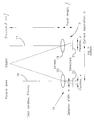
- Human beings have two eyes 1 and 2 as shown in Figure 1 of the accompanying drawings.
- the eyes are disposed side by side, separated by a distance that varies from person to person but averages at about 65mm.
- the eyes see a three dimensional world from two slightly different points of view as illustrated at 3 and 4.
- Objects such as 5 and 6 close to the eyes are seen from different angles and such objects appear shifted, relative to more distant objects such as 7, when the views from both eyes are compared as shown at 8.
- This shift is called 'Parallax'. This parallax is dependent on the distance from the eyes such that the further away the objects are, the smaller is the shift or parallax.
- 'Binocular Vision This is known as 'Binocular Vision' and enables a person to judge distance to an object and thus assess size when no other cue (such as motion, memory or perspective) exists to judge the distance. This ability to judge the distance is called 'Stereopsis', meaning 'solid seeing'.
- any display can be only as good as the photographs or images that are presented to it.
- Figure 2 of the accompanying drawings illustrates the "real world" situation where the eyes 1 and 2 look at objects 6 and 7 at different distances from the eyes.
- the "optical axes" of the eyes converge on the object 7 and the eyes focus on a focus plane 9 at the object.
- the optical axes converge and the eyes focus at another focus plane 10.
- Figure 2 also illustrates what happens during 3D viewing of a display having a display screen 11. Irrespective of the apparent distance of the images 12 and 13 from the viewer, the eyes 1 and 2 must maintain the display screen 11 in focus. Images such as 12 which appear in front of the screen have negative parallax whereas images such as 13 which appear behind the screen have positive parallax. Although the eyes 1 and 2 must maintain the screen 11 in focus, eye convergence has to vary according to the perceived distance to the image. Thus, in a 3D photograph, the parallax defines the convergence in the usual way but the eyes must have the fixed distance to the photograph or screen remaining in focus.
- GB 2 250 604 refers to an adapter that can be attached to any camera.
- This adapter contains two mirrors and a zoom lens. The convergence of the mirrors and zoom compensation are controlled by computer to obtain two homologous images with maximal overlap.
- WO 96/15631 refers to a method called "Disparity Shifting" where two homologous images are superimposed as anaglyph with an offset in the x and y directions. This artificially changes the parallax on the 3D image to compensate for zoom, convergence, etc. changing the parallax.
- GB 2 168 565 refers to a two-camera apparatus, adjustable according to separation, zoom and convergence.
- the zoom is optical and is effected on both cameras equally by a mechanism presented in the patent.
- the three variables can be controlled by microcomputer according to input data. No indication of how the relationship between zoom and interaxial separation is obtained for comfortable images is given. Further, the apparatus is limited to cameras whose optical axes converge so that this document teaches away from the use of parallel optical axes.
- a disadvantage with converging cameras is that they produce vertical parallax in the captured images (ie. keystone distortion).
- JP 9-215012 discloses a 2D/3D video camera incorporating 2D and 3D video images.
- the images are displayed on an LCD panel on the camera and viewed using a separate stereoscope.
- the 3D images are captured by two fixed camera heads.
- US 4 768 049 refers to a method of positioning a single camera in two positions accurately using a slide bar, referring directly to stereo photography. Such a camera cannot capture accurate still images of moving scenes.
- US 5 063 441 discloses a stereoscopic video camera with parallel optical axes and camera image sensor elements which are adjustable so that the sensors are exposed to different portions of the images from respective lenses. However, the separation between zoom lenses of the camera is fixed.
- US 4 418 993 discloses an arrangement for controlling convergence and separation so as to maintain an object at the image centre when zoom is effected in order to reduce the parallax of the object to comfortable limits.
- simultaneously control of three parameters is required and, because of the convergence of the optical axes, acceptable results cannot be obtained with distant backgrounds. Converging the cameras also produces unacceptable results due to keystoning. Also, such a system is expensive and complex and is not easily controlled by an unskilled user.
- a three dimensional camera comprising: at least one imaging and detecting device which is moveable in a direction substantially perpendicular to the optical axis thereof; defining means for defining a depth range of a scene whose image is to be captured at first and second positions; and deriving and limiting means for deriving as a function of the depth range a separation between said first and second positions and for limiting the separation such that the parallax between images captured at the first and second positions is less than a predetermined maximum parallax, wherein the optical axes of the or each device in said first and second positions are parallel.
- the at least one device may comprise at least two imaging and detecting devices whose optical axes are substantially parallel to each other.
- the camera may comprise a visual indicator for indicating whether a stereoscopic image to be captured is within predetermined parallax limits.
- the indicator may comprise a viewfinder or an indicator light.
- the predetermined maximum parallax may be a function of a predetermined display geometry on which captured images are intended to be displayed.
- the predetermined display geometry may comprise display screen size, intended viewing distance and eye separation.
- the defining means may be arranged to define at least one fixed depth range limit.
- the at least one fixed depth range limit may comprise infinity.
- the at least one fixed depth range limit may comprise a camera minimum focus distance.
- the defining means may comprise first selecting means for manually selecting the depth range.
- the first selecting means may be arranged to provide manual entry of the depth range or to select from a plurality of predetermined depth ranges.
- the defining means may be arranged to measure at least one depth range limit.
- the defining means may comprise an auto-focus sensor.
- the at least one depth range limit may comprise a near depth point.
- the defining means may comprise second selecting means for manually selecting from a plurality of fixed far depth points.
- the or each device may have a variable field of view.
- the camera may comprise third selecting means for manually selecting one of the separation and the field of view and fourth selecting means for automatically selecting the other of the separation and the field of view as a function of the one of the separation and the field of view.
- the function may be a monotonically increasing function.
- the function may also be a function of the maximum and minimum distances from the camera of objects whose images are to be captured.
- the function may also be a function of the geometry of a display for displaying images captured by the camera.
- the camera may comprise means for supplying to the fourth selecting means data representing the display size and viewing distance.
- the devices may be substantially identical to each other.
- the detectors of the devices may be disposed in a common plane substantially perpendicular to the optical axes.
- the detector of at least one of the devices may be offset laterally with respect to the optical axis of the device.
- the field of view of each device may be selectable by selecting a portion of the detector.
- each device may be selected by adjusting the focal length of an imaging optical system of the device.
- the devices may comprise zoom lenses whose optical nodes are disposed in at least one common plane perpendicular to the optical axes.
- One of the devices may be fixed.
- the camera may comprise more than two devices with the spacings between adjacent pairs of the devices being maintained substantially equal to each other.
- the detector of each device may be rotatable through substantially 90° about the optical axis of the device.
- the detector of each device may comprise a charge-coupled device.
- a 3D camera which is capable of capturing images over a wide range of distances from the camera. By limiting the maximum parallax which is captured, subsequently displayed captured images are viewed comfortably by a viewer.
- a camera may provide hard copies, for example in the form of photographs, or may supply images which are stored electronically, for example in semiconductor memories, floppy disks and CD ROMs.
- the camera may also be in the form of a video camera for capturing moving 3D images, for example for display on a suitable video rate 3D display.
- the user manually changes the separation of the device and the field of view or zoom setting is automatically calculated and applied using, for example, pre-set or manually input values of display geometry, human factors and/or distance ranges.
- display geometry For cameras including autofocus systems, such systems may provide distance data directly.
- the zoom function maintains the same parallax conditions for viewing. It is thus possible to provide a compact 3D camera which is easy to handle.
- Extra-wide base line 3D photographs or other captured images are possible if one device is detachable or extendable, for example on a slide. Also, objects with maximum depths of less than infinity can be imaged into a more useful depth on a display.
- Such a camera may also be used in a two dimensional (2D) mode, for example to allow 2D digital photographs to be easily obtained.
- one or more of the devices may be "toed-out" so as to allow an extra wide 2D panoramic picture to be obtained, for example when processed by means of seam matching software.
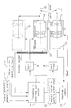
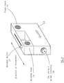
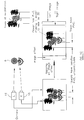
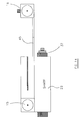
- Figures 3 and 4 illustrate a 3D camera comprising two detector or camera heads 15 and 16.
- the head 15 is fixed with respect to the body 23 of the camera, whereas the head 16 is moveable as far as the position shown at 16'.
- the heads 15 and 16 have optical axes 17 and 18 which are parallel to each other irrespective of the separation between the detector heads 15 and 16.
- Each of the detector heads comprises a lens 19, 20 in the form of a zoom lens and a detector 21, 22 in the form of a charge - coupled device sensor.
- the detector heads 15 and 16 are substantially identical to each other and the detectors 21, 22 are disposed in a common plane which is perpendicular to the optical axes 17 and 18.
- the moveable head 16 is arranged to move along a slide such that the optical axes 17 and 18 remain parallel to each other and the detectors 21, 22 remain in the common plane perpendicular to the optical axes.
- the lateral separation of the heads 15 and 16 is controlled by a user.
- the head 16 may be moved mechanically along the slide by means of a moveable button 27 fixed to the head 16 and pushed by the finger of the user.
- a dial 28 with a screw-mounting for the head 16 may be rotated by the user so as to adjust the separation between the heads 15 and 16.
- the button 27 or the dial 28 controls electromechanical means for moving the head 16.
- the position of the moveable head 16 is determined by a position encoder 25 and supplied to a circuit 24 for determining the field of view or focal length of the lenses 19 and 20.
- the position encoder 25 may comprise a linear potentiometer.
- position encoding may be provided by counting steps of the motor.
- the circuit 24 controls zoom motors 26 and 29, which control the focal lengths of the zoom lenses 19 and 20. In particular, the focal lengths are synchronised with each other so as to have the same value.
- the circuit 24 also receives details of the geometry of the display for which the captured images are intended from determining means 30. This may, for example, be in the form of preset values referring to a typical display screen size and typical intended viewing distance. Alternatively, the means 30 may permit a user to enter the appropriate data for a specific display.
- the circuit 24 further receives object depth information from object depth determining means 31.
- the object depth determining means 31 may allow manual selection, for instance by inputting distances from the camera to the nearest and furthest points in the image to be captured or by selecting from several preset depth ranges that which is most appropriate to the image to be captured.
- the object depth determining means 31 merely specifies the far point at infinity and the near point at the minimum focusing distance of the camera.
- the autofocus sensor may supply one or more of the depth range limits. For maximum flexibility, it may be possible to point the autofocus sensor at the nearest and furthest points in the image to be captured so that accurately measured distance data are supplied to the circuit 24.
- the far point is preset, for example at infinity, and the autofocus sensor is used to measure the distance to the near point.
- the far point may be manually selected from a set of options while the autofocus sensor determines the near point.
- the circuit 24 supplies a visual feedback 32 to indicate whether the camera is operating within the allowed conditions. For example, if at any point the maximum parallax condition is exceeded, a visual indicator which may be integrated into a viewfinder or display 33 can indicate to the user that the images captured with the existing settings of the camera will not be suitable. Similarly, an indication may be provided to show that too little depth is likely to be recorded for satisfactory 3D perception of the captured images.
- the images captured by the detectors 21, 22 are supplied to processing electronics, for example forming part of the electronics 24, which process the captured images as required and supply outputs, for example to a computer for subsequent processing and/or display.
- the camera and/or the computer may include printers for providing hard copies of the images, for example for viewing by means of a stereoscope.
- the display may be of electronic type, for example as disclosed in EP 0 602 934, EP 0 625 861, GB 2 321 815, EP 0 860 728, GB 2 317 295 and EP 0 829 744.
- the camera electronics 24 receive the signals representing the separation between the heads 15 and 16 from the position encoder 25 for sensing the position of the moveable head 16.
- the camera electronics 24 supply signals for controlling the focal length of the zoom lenses 19, 20 so as to determine the field of view of the camera as a monotonically increasing function of the separation between the heads 15 and 16.
- the lenses 19, 20 are controlled so as to have the widest field of view.
- the lenses 19, 20 are controlled so as to have the narrowest field of view in the available range.
- the field of view may be controlled by selecting in the camera electronics 24 the proportion of the light sensitive surface of the detectors 21, 22 at which the images are to be captured. This may be used to allow fixed focal length lenses to be used or to augment the field of view range provided by zoom lenses.
- the viewfinder or display 33 which may comprise a liquid crystal display and which may be integral with the camera or separate therefrom, allows a user to compose the desired image.
- the image captured by at least one of the detector heads 15, 16 is supplied via the camera electronics 24 to the viewfinder 33.
- the viewfinder 33 provides a 2D display, because a 3D display is not necessary for composing the view and may not accurately show stereoscopic images included for a different type of display.
- any 3D display provided in the camera would generally be of much smaller size than the intended display, which may for example be a work station display.
- the display of the same image on a larger display would substantially change the absolute parallax of the final displayed image.
- the 3D image captured for a small display is not likely to be suitable for a large image. It is therefore preferable not to compose the 3D image by means of the camera display but instead to provide an automatic arrangement for comfortable 3D image capture for the intended or target display.
- the viewfinder 33 is used for framing the image and the user can compose a reliable 3D image without the need to examine the image during the capture process.
- the user zooms the image seen on the viewfinder 33 to compose the 2D image.
- the zoom mechanism may be by means of adjustment of the focal length of each of the two lenses 19, 20, by varying the proportion of the image sensor displayed or by a combination of the two methods.
- the means by which the user controls the zoom setting is by lateral translation of the detector head 16 with respect to the head 15 such that the inter-axial separation of the two camera heads varies.
- the camera shown in Figure 5 differs from that shown in Figure 3 in that the lenses 19 and 20 are of fixed focal length so as to provide a fixed field of view.
- the zoom motors 26 and 29 are therefore not necessary.
- the following operation may be adopted if the user is able to fix the focal length.
- the depth range of a scene may change, in which case the separation between the heads 15 and 16 may be adjusted to compensate for the different depth range.
- a user may adjust the separation of the heads 15 and 16 so that the parallax captured for the particular scene depth range is restricted to be within predetermined limits.
- the camera display 33 may have a display icon such as a green light to show the separation at which the parallax captured by the camera is within acceptable limits based on the scene depth supplied to the camera. If the parallax is too large or too small, a red indicator may be shown on the display.
- a warning may be given to the user if there is too much or too little depth in the scene for the current conditions. Such a situation may occur if the depth range is so large that the required separation between the heads 15 and 16 is smaller than the minimum separation which is achievable with the mechanical design of the camera. In the non-zoom camera shown in Figure 5, the warning may be used to set optimum separation.
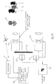
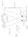
- Figure 6 illustrates an example of operation of a camera of the type shown in Figure 3 having an object depth determining means 31 in the form of an auto-focus system which detects the near point, the far point being fixed at infinity.
- the upper part of Figure 6 illustrates the separation and zoom lens settings for a scene where the nearest object detected by the auto-focus system 31 is at 6 with the background 7 approaching infinity.
- the middle part of Figure 6 illustrates what happens when a closer object 5 enters the scene.
- the field of view has to increase so as to maintain the maximum parallax condition.
- the electronics 24 cause the lenses of the heads 15 and 16 to adjust the zoom setting automatically and the user sees this on the viewfinder 33.
- the user may then adjust the separation as illustrated in the lower part of Figure 6 so that the electronics 24 alter the focal lengths of the zoom lenses to reframe the image correctly as required by the user.
- the separation of the heads 15 and 16 is reduced so that the maximum parallax condition is maintained. If the separation required for the depth range of the scene is smaller than is allowed mechanically, an indicator warns the user that the maximum parallax condition has been exceeded for the available depth of scene.
- Such a 3D camera produces two homologous images from two slightly different points of view of the same scene.
- An object in the field of view will appear in slightly different lateral positions on the two images.
- the separation of the two lateral positions depends on the distance of the object from the camera and is called parallax.
- Autostereoscopic and stereoscopic display devices are well known and operate by presenting each eye of an observer with separate images.
- each detector 21, 22 sees one of the two captured images and the image parallax recorded in the capture stage is replayed to the observer.
- the images are fused to give the impression of an image with depth.
- the camera allows the user to control the amount of parallax captured by a 3D camera such that, when the images are replayed, a comfortable amount of depth may be presented. In particular, no knowledge by the user of 3D geometry requirements is needed during image capture.
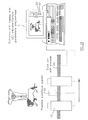
- Figure 7 illustrates the camera geometry, in which f is the focal length of the lenses 19, 20, w is the image sensor width of the detectors 21, 22, a is the separation of the detector heads 15, 16 and ⁇ is the distance from the camera to the object being photographed.
- the horizontal parallax, P produced by this geometry between the two homologous images in the camera is:
- the negative sign is chosen using the convention that negative parallaxes are in "theatre space", i.e. a point on the left image is to the right of the homologous point in the right image. Such a parallax will produce an apparent position in front of the screen, as the eyes have to converge more than that required for the screen, and vice versa for "screen space” parallaxes.
- the final image will have a width D. If the image fills the whole screen, then D is equal to the display screen width.
- the ratio of the parallax to the image width remains constant irrespective of the type of display or width of image because parallax scales linearly with display size. This ratio is equal to P s /D, where P s is the parallax seen on the 3D display.
- equation [2] can be written in the following form:
- Figure 8 illustrates the camera capturing images of the objects 5, 6 and 7 of the type shown in Figure 1.
- objects at infinity appear to be at the screen plane. All objects at a finite distance will be imaged with negative parallax and appear to be in front of the screen as illustrated by the images 5', 6', 7' of the objects 5, 6, 7. Images such as 5' appear closer than a plane of minimum parallax and are uncomfortable to a viewer. It is often considered desirable to give infinity a positive parallax at a position behind the screen (i.e. in "screen space”), for example at a plane 36 of maximum parallax.
- P ss The maximum positive parallax that can be comfortly viewed is represented by P ss and the minimum theatre space (or negative or crossed) parallax is represented by -P TS .
- P ss the minimum theatre space (or negative or crossed) parallax is represented by -P TS .
- -P TS the minimum theatre space
- ⁇ ⁇
- the displayed parallax, Ps/D should not exceed the minimum negative parallax observable, -P TS /D.
- ⁇ ⁇ P SS / D + P TS / D + ⁇ / R .
- a comfortable 3D image can be obtained with objects at a distance ⁇ being in the plane of the screen when taken with a camera set up in a configuration defined by the value of a alone.
- the maximum depth allowed on the display is determined to be 60mm in theatre space and 120mm in screen space.
- a two head camera of image sensor width 5mm and zoom focal length range 6-20mm (field of view angle 45° to 14°) is used to capture the stereo image of an object with a depth range from 1.5m to infinity.
- the object parameter, ⁇ is 83mm and the ZDP distance, ⁇ , is 2.5m.
- an encoder on the translation stage measures the separation of the two detector heads 15, 16.
- the user would like a focal length of 12mm from the viewfinder corresponding to a field of view of 23.5° from equation [3]. Equation [5] thus indicates that a separation of 35mm would need to be achieved by the user.
- the zoom lens is controlled so that the focal length is 12mm.
- the separation of the detector heads 15, 16 has already been set for comfortable viewing under the defined display conditions.
- the user hits the record button and a pair of images is captured.
- the images in digital cameras may be stored together with data on original parallax requirements, focal length, CCD size and detector head separation.
- the user would like a focal length of 6mm and so moves the detector head so as to change the separation until this is achieved.
- the required separation is 69mm.
- the user enters into a menu on the camera the new display size.
- the maximum allowable P/D values drop to -1.6% and 2.4%.
- the object parameter is now 60mm.
- a camera head separation of only 50mm is used.
- the target display size range may be entered e.g. 3-8", 8-17", 17-25", 25-40", 40"+ (corresponding approximately to 76-203mm, 203-432mm, 432-635mm, 635-1016mm, 1016mm+).
- the worst case image conditions will be considered in setting maximum parallaxes.
- the object scene has assumed a maximum depth range of infinity. This may well be true in many outdoor situations but often the far distance will be finite, for example in a room.
- an image with range from 0.5m to 2m would need a separation of 15mm for a 12mm focal length on a 300mm wide screen, the object parameter being 37mm.
- Such object distances may be input through a keypad or touch screen based user interface, or alternatively through a dial 37 as shown in Figure 12.
- Autofocus sensors on cameras are used to range-find to points or areas in the scene.
- the sensors are generally based on an infra-red illumination of the object for ranges up to several metres. Sometimes ultra-sonic sensors are also used. Generally this data is subsequently used to set the focus position of a lens. However, for stereo imaging, useful data on object depth content can be obtained. Autofocus data from the camera can thus be used to measure the close point and perhaps far point of a scene. The information from this sensor is fed back into the control mechanism.
- the system can be used, for a camera with a given object parameter ⁇ , to determine the distance to the closest object in the field of view. This may be used to indicate, e.g. by way of a red/green LEDs 38 or similar, whether the object is closer or further than the minimum 3D distance, ⁇ . It may also, if closer than ⁇ , prevent a photograph from being taken.
- multi-point spot focussing is available.
- the distance to a number of points in an object can be recorded. It may be possible to extract such date to ascertain near and far point distances and, using the camera equations, adjust the interaxial separation accordingly.
- One autofocus system could be used for each of the physical parameters necessary.
- a user interface on the display.
- a user interface may be by means of dials 37 or by means of an interfaced computer as shown in Figure 12, or by a user interface on the camera itself, such as by means of a touch screen display on the camera.
- the parameters used when the image was captured could be stored as a magnetic stripe on the back of prints or in file headers.
- the image size to be displayed can be manipulated so as to give the maximum viewing comfort of the image for the new display. For instance, an image which was captured for viewing on a 10" (254mm) diagonal display is replayed on a 20" (508mm) diagonal display, but from the same viewing distance. If the original capture conditions are contained in an image file, it is possible to automatically zoom the image so that it is only 10" diagonal so as to maintain comfortable viewing conditions.
- two (or more) values of the object parameter are pre-programmed in the camera where the value taken depends on the autofocus reading at a particular time.
- a dial 37 selects, for example, from values for landscape 40, mid-field (outdoor) 41, mid-field (indoor) 42 and macro 43.
- a nominal viewing condition is assumed in this case or pre-programmed for optimal comfort of viewing.
- autofocus data can also be used to check the viability of a 3D photograph of a scene from a manual choice of distances chosen by the user using a dial or switch or downloaded from a computer.
- the screen crop is calculated from equation [11], with the offset excluded in brackets.
- C Far field ⁇ 0.192m 2.4m 3.9m 10%(5%) Mid field (outdoor) ⁇ 0.13m 1.63m 2.61m 10%(5%) Mid field (indoor) 10m 0.13m 1.4m 2.06m 12%(6%) Macro 2m 0.13m 0.9m 1.13m 23%(12%)
- the system can also be used in a further embodiment in the following way.
- the value of the object parameter, display geometry, and the minimum and maximum distances or personal parallax limits can be programmed into a computer and the instructions can be downloaded into the camera. It can also be realised using dials and switches on the camera itself to determine these limits or programmed directly through buttons and an LCD display on the camera. These possibilities are illustrated in Figure 12.
- the validity of the input data can be checked internally inside the camera in software.
- An autofocus system (or more than one) can be used to check that the chosen scene is within these programmed limits. It can be displayed on the LCD as suggested modifications to the input data or as a simple two-colour LED.
- the files may be stored in many forms, as compressed or uncompressed files containing the two images plus camera set-up data, or the parallaxes may be estimated from the images and stored as a single image plus a depth map.
- the software may process the images to achieve the following:
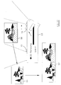
- one head may be made detachable or the slide 45 extendable as shown in Figure 14 to achieve a very wide baseline separation for extra stereoscopic resolution on very distant landscape or mountain shots.
- Post processing can also be applied.
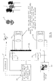
- the camera has more than two detector heads.
- the camera has a single fixed detector head 15 and two moveable detector heads 16a and 16b.
- the heads 16a and 16b are constricted to move in a lateral direction perpendicular to the optical axes of the detector heads.
- the moveable detector heads 16a and 16b are linked or controlled in such a way that the spacing 47 between the detector heads 15 and 16a is maintained equal to the spacing 48 between the detector heads 16a and 16b.
- the relationship between each head and its position relative to the others must still satisfy the object parameter relationships so that a single button 27 can control all three (or more) heads on the camera to effect the zoom. All of the features described hereinbefore may be incorporated into such a camera without significant alteration in their characteristics.
- Such a camera may be used for 3D displays which require three (or more) images to be displayed.
- the camera may have two heads, one movable and encoded with the zoom automatically by one fixed pre-set object parameter.
- the parallax, ZDP and object maximum and minimum settings may be similarly pre-set so as to be as universally applicable as possible.
- Example settings may be parallaxes -3%, 5%, object parameter 0.13mm, minimum distance 1.6m, maximum distance infinity and ZDP plane 2.6m.
- the camera may also have a single autofocus indicator to detect the minimum distance via a green/red indicator.
- a LCD display is provided for framing the zoom. The user need only point the camera, move one head to frame the zoom and take the picture. Everything else is done automatically before, for example, downloading to a computer and display.
- the motion of one or more heads in the above cameras may be motorised with manual or computer control.
- Lens aberrations may cause some degradation of the images, particularly as the images are offset on the detectors. Lenses with improved field curvature and distortion characteristics may be preferable to enhance the matching of the two images on the final display. Any such errors would otherwise cause image misalignment which varies across the display resulting in viewer discomfort.
- the camera In conventional cameras, to take portrait mode images, the camera is simply rotated.
- each of the images needs to be separately rotated by 90° while the head separation remains horizontal.
- the detector heads may each be rotated in order to allow portrait stereo images to be captured.
- the detectors may be rotated through 90° for portrait mode pictures.
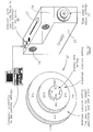
- the camera has a single detector head 16 mounted on a slide bar 45, as shown in Figure 16.
- An autofocus system 50 may be included.
- the photographer frames the image and takes a picture, at which point the zoom setting is encoded.
- the control computer then computes the required new position of the detector head 16 based on the encoded zoom setting.
- the detector head 16 is then moved manually or automatically along the slide bar 45.
- An encoder measures the detector head position. As the detector head 16 moves, a red LED 51 is illuminated in a position where the separation is too large for a good stereo photograph and, when the head is at the appropriate point, a green LED 52 indicates the correct position, at which a second image can be captured with the same zoom setting as used previously.
- a yellow LED can indicate a position where a photograph will produce a good stereo photograph but the stereo depth is not fully utilised, i.e. the separation is too small.
- the detector head 16 may be moved continuously and fired automatically at the appropriate point.
- a fast shutter speed or auxiliary lighting may be required.
- the user does not have to be concerned about accurately positioning the camera.
- a motor can translate the detector head 16. In this way, a fully automatic rig is provided which just requires the photographer's skill to frame the image by pointing direction and zoom settings.
- Such a camera has all of the functionality previously described but may not be suitable for imaging moving objects. Photographers can concentrate on image composition without the need to be concerned about 3D geometry requirements. In particular, this system allows standard cameras to be mounted on the rail, so that the cost of stereo imaging is reduced. The camera can be controlled completely automatically.
- Figure 17 illustrates another camera in which the head 16 can be toed out by an angle slightly less than half the field of view angle so that the fields of view just overlap.
- the images 55 and 56 are seam matched in software to give extra long 2D panoramic prints 57.
- the detector heads may be placed adjacent each other so that there is negligible stereo base and an image with enhanced image resolution can be obtained by combining the two images.
Abstract
Description
- The present invention relates to a stereoscopic three-dimensional (3D) camera. Such a camera may be used in consumer and professional photography, 3DTV, police identification, medical imaging, and scientific visualisation.
- Human beings have two
eyes - This is known as 'Binocular Vision' and enables a person to judge distance to an object and thus assess size when no other cue (such as motion, memory or perspective) exists to judge the distance. This ability to judge the distance is called 'Stereopsis', meaning 'solid seeing'.
- The discovery of stereopsis and photography were put together early. If a camera could mimic one eye and produce a 2D photograph, then it was assumed that two cameras, set up at a similar distance apart as the human eyes, could mimic the 3D stereopsis effect as well. Each photograph mimics the image taken from each eye with the corresponding parallax and shifts necessary to judge distance by stereopsis alone. The two photographs thus obtained would need to be displayed to an observer with one photograph to one eye and the other to the other.
- A small system of lenses achieved this. Known as a Stereoscope, it was quite popular among upper and middle class families by the 1850's. It was not long after the invention of moving pictures that moving 3D films were shown.
- Many methods of display are known including the stereoscope, anaglyph (red/green glasses) and LCD switchable glasses, autostereoscopic methods (where no glasses at all are required), head tracking displays and virtual reality. However, any display can be only as good as the photographs or images that are presented to it.
- Figure 2 of the accompanying drawings illustrates the "real world" situation where the
eyes objects distant object 7, the "optical axes" of the eyes converge on theobject 7 and the eyes focus on afocus plane 9 at the object. Conversely, when the eyes focus on anearer object 6, the optical axes converge and the eyes focus at anotherfocus plane 10. - Figure 2 also illustrates what happens during 3D viewing of a display having a
display screen 11. Irrespective of the apparent distance of theimages eyes display screen 11 in focus. Images such as 12 which appear in front of the screen have negative parallax whereas images such as 13 which appear behind the screen have positive parallax. Although theeyes screen 11 in focus, eye convergence has to vary according to the perceived distance to the image. Thus, in a 3D photograph, the parallax defines the convergence in the usual way but the eyes must have the fixed distance to the photograph or screen remaining in focus. - It is well known that a certain amount of mismatch between accommodation and convergence is considered to be tolerated comfortably, allowing 3D photography to function within limits of depth either side of the focus distance. This results in limitations to the parallax on the photographs in the horizontal direction. In addition, significant vertical parallaxes can cause serious viewer fatigue.
- This places significant tolerances on the cameras, their design, construction and use. The parallax produced on the photographs depends on many variables, e.g. the separation of the cameras, zoom and field of view, convergence, display method, etc. They must all be controlled so as to keep both horizontal and vertical parallaxes on the two photographs within comfortable limits. In known systems, this requires specialist knowledge and experience on the part of the cameraman.
- Many designs for cameras have been made. The three most common are a single camera moved on a slide, a single camera with extra mirrors and optics, and a two camera design. The following references provide representative prior art in this field.
- "Foundations of the stereoscopic cinema" Lipton. Van Nostrand, 1982 ISBN 0-442-24724-9 pages 114 to 115 describe one form of the camera equation which is described hereinafter.
-
GB 2 250 604 refers to an adapter that can be attached to any camera. This adapter contains two mirrors and a zoom lens. The convergence of the mirrors and zoom compensation are controlled by computer to obtain two homologous images with maximal overlap. - WO 96/15631 refers to a method called "Disparity Shifting" where two homologous images are superimposed as anaglyph with an offset in the x and y directions. This artificially changes the parallax on the 3D image to compensate for zoom, convergence, etc. changing the parallax.
-
GB 2 168 565 refers to a two-camera apparatus, adjustable according to separation, zoom and convergence. The zoom is optical and is effected on both cameras equally by a mechanism presented in the patent. The three variables can be controlled by microcomputer according to input data. No indication of how the relationship between zoom and interaxial separation is obtained for comfortable images is given. Further, the apparatus is limited to cameras whose optical axes converge so that this document teaches away from the use of parallel optical axes. A disadvantage with converging cameras is that they produce vertical parallax in the captured images (ie. keystone distortion). - JP 9-215012 discloses a 2D/3D video camera incorporating 2D and 3D video images. The images are displayed on an LCD panel on the camera and viewed using a separate stereoscope. The 3D images are captured by two fixed camera heads.
- US 4 768 049 refers to a method of positioning a single camera in two positions accurately using a slide bar, referring directly to stereo photography. Such a camera cannot capture accurate still images of moving scenes.
- US 5 063 441 discloses a stereoscopic video camera with parallel optical axes and camera image sensor elements which are adjustable so that the sensors are exposed to different portions of the images from respective lenses. However, the separation between zoom lenses of the camera is fixed.
- US 4 418 993 discloses an arrangement for controlling convergence and separation so as to maintain an object at the image centre when zoom is effected in order to reduce the parallax of the object to comfortable limits. However, simultaneously control of three parameters is required and, because of the convergence of the optical axes, acceptable results cannot be obtained with distant backgrounds. Converging the cameras also produces unacceptable results due to keystoning. Also, such a system is expensive and complex and is not easily controlled by an unskilled user.
- According to the invention, there is provided a three dimensional camera comprising: at least one imaging and detecting device which is moveable in a direction substantially perpendicular to the optical axis thereof; defining means for defining a depth range of a scene whose image is to be captured at first and second positions; and deriving and limiting means for deriving as a function of the depth range a separation between said first and second positions and for limiting the separation such that the parallax between images captured at the first and second positions is less than a predetermined maximum parallax, wherein the optical axes of the or each device in said first and second positions are parallel.
- The at least one device may comprise at least two imaging and detecting devices whose optical axes are substantially parallel to each other.
The camera may comprise a visual indicator for indicating whether a stereoscopic image to be captured is within predetermined parallax limits. The indicator may comprise a viewfinder or an indicator light. - The predetermined maximum parallax may be a function of a predetermined display geometry on which captured images are intended to be displayed. The predetermined display geometry may comprise display screen size, intended viewing distance and eye separation.
- The defining means may be arranged to define at least one fixed depth range limit. The at least one fixed depth range limit may comprise infinity. The at least one fixed depth range limit may comprise a camera minimum focus distance.
- The defining means may comprise first selecting means for manually selecting the depth range. The first selecting means may be arranged to provide manual entry of the depth range or to select from a plurality of predetermined depth ranges.
- The defining means may be arranged to measure at least one depth range limit. The defining means may comprise an auto-focus sensor. The at least one depth range limit may comprise a near depth point. The defining means may comprise second selecting means for manually selecting from a plurality of fixed far depth points.
- The or each device may have a variable field of view. The camera may comprise third selecting means for manually selecting one of the separation and the field of view and fourth selecting means for automatically selecting the other of the separation and the field of view as a function of the one of the separation and the field of view.
- The function may be a monotonically increasing function.
- The function may also be a function of the maximum and minimum distances from the camera of objects whose images are to be captured.
- The function may also be a function of the geometry of a display for displaying images captured by the camera. The camera may comprise means for supplying to the fourth selecting means data representing the display size and viewing distance.
- The devices may be substantially identical to each other.
- The detectors of the devices may be disposed in a common plane substantially perpendicular to the optical axes.
- The detector of at least one of the devices may be offset laterally with respect to the optical axis of the device.
- The field of view of each device may be selectable by selecting a portion of the detector.
- The field of view of each device may be selected by adjusting the focal length of an imaging optical system of the device. The devices may comprise zoom lenses whose optical nodes are disposed in at least one common plane perpendicular to the optical axes.
- One of the devices may be fixed.
- The camera may comprise more than two devices with the spacings between adjacent pairs of the devices being maintained substantially equal to each other.
- The detector of each device may be rotatable through substantially 90° about the optical axis of the device.
- The detector of each device may comprise a charge-coupled device.
- It is thus possible to provide a 3D camera which is capable of capturing images over a wide range of distances from the camera. By limiting the maximum parallax which is captured, subsequently displayed captured images are viewed comfortably by a viewer. Such a camera may provide hard copies, for example in the form of photographs, or may supply images which are stored electronically, for example in semiconductor memories, floppy disks and CD ROMs. The camera may also be in the form of a video camera for capturing moving 3D images, for example for display on a
suitable video rate 3D display. - A user need not have specialist knowledge in order to obtain 3D images which are suitable for display while providing good-
quality 3D appearance. For example, in one form, the user manually changes the separation of the device and the field of view or zoom setting is automatically calculated and applied using, for example, pre-set or manually input values of display geometry, human factors and/or distance ranges. For cameras including autofocus systems, such systems may provide distance data directly. In this case where the user manually selects the device separation, the zoom function maintains the same parallax conditions for viewing. It is thus possible to provide a compact 3D camera which is easy to handle. -
Extra-wide base line 3D photographs or other captured images are possible if one device is detachable or extendable, for example on a slide. Also, objects with maximum depths of less than infinity can be imaged into a more useful depth on a display. - Such a camera may also be used in a two dimensional (2D) mode, for example to allow 2D digital photographs to be easily obtained. Furthermore, one or more of the devices may be "toed-out" so as to allow an extra wide 2D panoramic picture to be obtained, for example when processed by means of seam matching software.
- The invention will be further described, by way of example, with reference to the accompanying drawings, in which:
- Figure 1 is a diagram illustrating parallax in human vision;
- Figure 2 is a diagram illustrating focusing and convergence when viewing objects and a 3D display;
- Figure 3 is a schematic diagram of a 3D camera constituting an embodiment of the invention;
- Figure 4 is a drawing illustrating a possible arrangement of the camera of Figure 3;
- Figure 5 is a schematic diagram of a 3D camera constituting another embodiment of the invention;
- Figure 6 is a diagram illustrating use of the camera of Figure 3;
- Figure 7 is a diagram illustrating the geometry of the camera of Figure 3;
- Figure 8 is a diagram illustrating zero disparity point correction;
- Figure 9 is a diagram illustrating the geometry of a camera of the type shown in Figure 3 but provided with detector offsets;
- Figure 10 is a diagram illustrating parallax shifting;
- Figure 11 is a diagram illustrating the geometry of the camera of Figure 3 and, in particular, illustrating screen cropping;
- Figure 12 is a drawing illustrating a modified arrangement of a 3D camera of the type shown in Figure 3;
- Figure 13 is a drawings illustrating another modified arrangement of a camera of the type shown in Figure 3;
- Figure 14 is a drawing illustrating a further arrangement of a camera of the type shown in Figure 3 for wider base line separation;
- Figure 15 is a drawing illustrating an arrangement of a three detector head camera constituting an embodiment of the invention;
- Figure 16 is a diagram illustrating a single detector head camera constituting an embodiment of the invention; and
- Figure 17 is a diagram illustrating use of a camera of the type shown in Figure 4 but modified for capturing panoramic 2D images.
-
- Like reference numerals refer to like parts throughout the drawings.
- Figures 3 and 4 illustrate a 3D camera comprising two detector or camera heads 15 and 16. The
head 15 is fixed with respect to thebody 23 of the camera, whereas thehead 16 is moveable as far as the position shown at 16'. Theheads optical axes lens detector detectors optical axes - The
moveable head 16 is arranged to move along a slide such that theoptical axes detectors heads head 16 may be moved mechanically along the slide by means of amoveable button 27 fixed to thehead 16 and pushed by the finger of the user. Alternatively, adial 28 with a screw-mounting for thehead 16 may be rotated by the user so as to adjust the separation between theheads button 27 or thedial 28 controls electromechanical means for moving thehead 16. - The position of the
moveable head 16 is determined by aposition encoder 25 and supplied to acircuit 24 for determining the field of view or focal length of thelenses moveable head 16 is moved by means of a stepper motor, position encoding may be provided by counting steps of the motor. Thecircuit 24 controls zoommotors zoom lenses - The
circuit 24 also receives details of the geometry of the display for which the captured images are intended from determiningmeans 30. This may, for example, be in the form of preset values referring to a typical display screen size and typical intended viewing distance. Alternatively, themeans 30 may permit a user to enter the appropriate data for a specific display. - The
circuit 24 further receives object depth information from objectdepth determining means 31. The objectdepth determining means 31 may allow manual selection, for instance by inputting distances from the camera to the nearest and furthest points in the image to be captured or by selecting from several preset depth ranges that which is most appropriate to the image to be captured. In a particularly simple arrangement, the objectdepth determining means 31 merely specifies the far point at infinity and the near point at the minimum focusing distance of the camera. In more sopisticated embodiments, for example where the camera is of the autofocus type, the autofocus sensor may supply one or more of the depth range limits. For maximum flexibility, it may be possible to point the autofocus sensor at the nearest and furthest points in the image to be captured so that accurately measured distance data are supplied to thecircuit 24. In a simpler arrangement, the far point is preset, for example at infinity, and the autofocus sensor is used to measure the distance to the near point. Alternatively, the far point may be manually selected from a set of options while the autofocus sensor determines the near point. - In addition to controlling the
zoom motors lenses circuit 24 supplies avisual feedback 32 to indicate whether the camera is operating within the allowed conditions. For example, if at any point the maximum parallax condition is exceeded, a visual indicator which may be integrated into a viewfinder ordisplay 33 can indicate to the user that the images captured with the existing settings of the camera will not be suitable. Similarly, an indication may be provided to show that too little depth is likely to be recorded for satisfactory 3D perception of the captured images. - The images captured by the
detectors electronics 24, which process the captured images as required and supply outputs, for example to a computer for subsequent processing and/or display. The camera and/or the computer may include printers for providing hard copies of the images, for example for viewing by means of a stereoscope. Alternatively, the display may be of electronic type, for example as disclosed inEP 0 602 934,EP 0 625 861,GB 2 321 815,EP 0 860 728,GB 2 317 295 andEP 0 829 744. - The
camera electronics 24 receive the signals representing the separation between theheads position encoder 25 for sensing the position of themoveable head 16. Thecamera electronics 24 supply signals for controlling the focal length of thezoom lenses heads heads lenses heads lenses - Alternatively or additionally, the field of view may be controlled by selecting in the
camera electronics 24 the proportion of the light sensitive surface of thedetectors - The viewfinder or
display 33, which may comprise a liquid crystal display and which may be integral with the camera or separate therefrom, allows a user to compose the desired image. In particular, the image captured by at least one of the detector heads 15, 16 is supplied via thecamera electronics 24 to theviewfinder 33. Thus, theviewfinder 33 provides a 2D display, because a 3D display is not necessary for composing the view and may not accurately show stereoscopic images included for a different type of display. For example, any 3D display provided in the camera would generally be of much smaller size than the intended display, which may for example be a work station display. If the user were to compose an image to have an acceptable depth range on such a small display, then the display of the same image on a larger display would substantially change the absolute parallax of the final displayed image. Thus, the 3D image captured for a small display is not likely to be suitable for a large image. It is therefore preferable not to compose the 3D image by means of the camera display but instead to provide an automatic arrangement for comfortable 3D image capture for the intended or target display. Theviewfinder 33 is used for framing the image and the user can compose a reliable 3D image without the need to examine the image during the capture process. - In order, for example, to take accurate stereo photographs, the user zooms the image seen on the
viewfinder 33 to compose the 2D image. As described above, the zoom mechanism may be by means of adjustment of the focal length of each of the twolenses detector head 16 with respect to thehead 15 such that the inter-axial separation of the two camera heads varies. Once the image is appropriately framed, the image is captured. The captured image may be still or moving for photographic or video applications, respectively. - The camera shown in Figure 5 differs from that shown in Figure 3 in that the
lenses zoom motors - It is possible that the depth range of a scene may change, in which case the separation between the
heads heads camera display 33 may have a display icon such as a green light to show the separation at which the parallax captured by the camera is within acceptable limits based on the scene depth supplied to the camera. If the parallax is too large or too small, a red indicator may be shown on the display. - In the cameras shown in Figures 3 and 5, a warning may be given to the user if there is too much or too little depth in the scene for the current conditions. Such a situation may occur if the depth range is so large that the required separation between the
heads - Figure 6 illustrates an example of operation of a camera of the type shown in Figure 3 having an object
depth determining means 31 in the form of an auto-focus system which detects the near point, the far point being fixed at infinity. The upper part of Figure 6 illustrates the separation and zoom lens settings for a scene where the nearest object detected by the auto-focus system 31 is at 6 with thebackground 7 approaching infinity. The middle part of Figure 6 illustrates what happens when acloser object 5 enters the scene. For the particular separation of theheads electronics 24 cause the lenses of theheads viewfinder 33. The user may then adjust the separation as illustrated in the lower part of Figure 6 so that theelectronics 24 alter the focal lengths of the zoom lenses to reframe the image correctly as required by the user. The separation of theheads - Such a 3D camera produces two homologous images from two slightly different points of view of the same scene. An object in the field of view will appear in slightly different lateral positions on the two images. The separation of the two lateral positions depends on the distance of the object from the camera and is called parallax.
- Autostereoscopic and stereoscopic display devices are well known and operate by presenting each eye of an observer with separate images. Thus, each
detector - The camera allows the user to control the amount of parallax captured by a 3D camera such that, when the images are replayed, a comfortable amount of depth may be presented. In particular, no knowledge by the user of 3D geometry requirements is needed during image capture.
- It is known in the prior art that parallel camera axes allow the capture of robust 3D images. In particular: images can be captured with no keystone distortion (which would otherwise lead to image degrading vertical parallax); objects at infinity can be captured with finite parallax; and the optical axis convergence is fixed, which means that the difficult process of adapting it to different image scenes is unnecessary.
- Figure 7 illustrates the camera geometry, in which f is the focal length of the
lenses detectors 
- The negative sign is chosen using the convention that negative parallaxes are in "theatre space", i.e. a point on the left image is to the right of the homologous point in the right image. Such a parallax will produce an apparent position in front of the screen, as the eyes have to converge more than that required for the screen, and vice versa for "screen space" parallaxes. During the 3D display of a pair of images, the final image will have a width D. If the image fills the whole screen, then D is equal to the display screen width.
- The ratio of the parallax to the image width remains constant irrespective of the type of display or width of image because parallax scales linearly with display size. This ratio is equal to Ps/D, where Ps is the parallax seen on the 3D display. Thus:

- To a first order approximation neglecting aberrations, the ratio f/w is related directly to the field of view, , of the camera through the equation:
- Hence, equation [2] can be written in the following form:

- Here, α is known as the Object Parameter and is only dependent on the camera characteristics and has a dimension of distance. It is defined by:
- In this configuration, objects at infinity will have zero parallax. For example, Figure 8 illustrates the camera capturing images of the
objects display screen 11, objects at infinity appear to be at the screen plane. All objects at a finite distance will be imaged with negative parallax and appear to be in front of the screen as illustrated by the images 5', 6', 7' of theobjects plane 36 of maximum parallax. Other objects in the scene are thus imaged around the screen plane as shown in Figure 8. This can be achieved by offsetting the detectors by small amounts as shown in Figure 9. Alternatively the two homologous images can be displaced horizontally relative to one another when displayed by a small percentage of the display width, Poffset/D, where Poffset is the offset parallax produced by superimposing the images with the horizontal offset. This gives a positive parallax to infinity and is called Zero disparity point (ZDP) correction as illustrated in Figure 10. When displayed, equation [4] thus takes the form: - This can be written as:where Λ is the distance from the camera to the ZDP plane. This plane is the distance at which an object, imaged by the camera, would appear level with the screen when fully displayed. It is defined by α/Λ=Poffset/D (and equation [7] follows from that).

- For a given viewing geometry of a 3D display, it is often considered in the art that there are maximum limits to the range of disparities it is acceptable to display to optimise viewer comfort while presenting useful depth cues. These maximum limits may vary dependent on at least the viewing distance, display size, size of image on the display, viewer eye separation and experience of users in
viewing 3D images. Given knowledge of these nominal conditions, values of appropriate limits to positive and negative parallax can be ascertained. - The maximum positive parallax that can be comfortly viewed is represented by Pss and the minimum theatre space (or negative or crossed) parallax is represented by -PTS. For the camera to capture appropriate images, these have to be normalised to a defined displayed image width (which may be equal to the screen width D if the image fills the whole screen) so that knowledge of both Pss/D and PTS/D (positive quantities) are thus required.
- The maximum positive parallax observable, Pss/D, can be set so that the maximum distance that the scene contains, ρ=R, would have exactly this parallax i.e. PS/D=PSS/D. In this case:

- At some minimum distance, ρ=η, the displayed parallax, Ps/D, should not exceed the minimum negative parallax observable, -PTS/D. Thus:
- Often, the maximum distance, R, would be infinite as is often the case for outdoor image capture. Assuming this:
- Hence, for objects at a distance between η and R, a comfortable 3D image can be obtained with objects at a distance Λ being in the plane of the screen when taken with a camera set up in a configuration defined by the value of a alone.
- The geometry of such a 3D image capture system is known in the prior art. However, prior art systems with fully adjustable characteristics have required users to have knowledge of these equations in order to capture acceptable images. The invention removes this requirement from the user.
- It is thus possible to capture images of objects with depth ranges of perhaps 1 metre to infinity and to display such images with a depth range of perhaps just 10cm on a typical workstation display. This results in depth compression distortion in the 3D image. Thus, fixing the maximum and minimum parallaxes implies fixing the perceived depth on the display for a particular user. This perceived depth range would then contain all the information taken by the camera. However, under some circumstances, the depth of the object can be mapped directly into the acceptable depth range that can be shown by the display. This is the orthoscopic condition.
- The parallel axes nature of the camera implies that some of the information taken in each image is lost due to the fact that not all of the two homologous images overlap as illustrated in Figure 11. This is known as screen cropping. The amount of width of view lost is always a, independent of the distance to the object, ρ. The size of the field at this distance is 2ρ tan (/2), and so the ratio lost is α/ρ, where α is given in equation [5]. There is also an extra crop due to an applied image sensor/ZDP correction offset. If this offset is by using a detector offset in the camera, no extra term need be added. If it is by "post process" ZDP correction, an extra term, Poffse/D, must be added. In all cases this crop is independent of the zoom position because of the relationship between the inter-axial separation and the field of view so that the object parameter is maintained at a constant value. The total crop, C, is thus, if a mean distance of the ZDP distance, Λ, is taken because an offset is applied:
- In one example of image capture, stereo images are to be viewed on a display of lateral width D = 300mm at a viewing distance of 600mm for an experienced user of eye spacing 59mm. For comfortable viewing freedom, the maximum depth allowed on the display is determined to be 60mm in theatre space and 120mm in screen space. Thus the maximum separation of the homologous points allowed is -6.6mm and +9.8mm (homologous points are two points, one in each homologous image, which are projections of the same real point in space). If we assume that the image is to be viewed at full screen width, then the ratios of parallax to screen width are -PTS/D=2.2% and Pss/D=3.3%.
- A two head camera of image sensor width 5mm and zoom focal length range 6-20mm (field of
view angle 45° to 14°) is used to capture the stereo image of an object with a depth range from 1.5m to infinity. From equations [8], [9] and [10] and the values of the parallaxes, the object parameter, α, is 83mm and the ZDP distance, Λ, is 2.5m. By viewing the image on a 2D LCD viewfinder, the user composes the image by physically moving one lens with respect to the other. This in turn changes the zoom setting of the image displayed on the viewfinder. - During translation of the camera head, an encoder on the translation stage measures the separation of the two detector heads 15, 16. The user would like a focal length of 12mm from the viewfinder corresponding to a field of view of 23.5° from equation [3]. Equation [5] thus indicates that a separation of 35mm would need to be achieved by the user. When the detector heads 15, 16 have been displaced so that the separation is 35mm, the zoom lens is controlled so that the focal length is 12mm. Thus, when the image is correctly composed, the separation of the detector heads 15, 16 has already been set for comfortable viewing under the defined display conditions. The user then hits the record button and a pair of images is captured. The images in digital cameras may be stored together with data on original parallax requirements, focal length, CCD size and detector head separation.
- In an alternative picture, the user would like a focal length of 6mm and so moves the detector head so as to change the separation until this is achieved. The required separation is 69mm.
- In an alternative picture, the optimal display size is changed to 20 inches (corresponding to a display width D=(4/5) x 508mm = 406mm) with the remainder of the viewing conditions fixed. In this case, the user enters into a menu on the camera the new display size. As the display size has grown but the maximum parallaxes are to remain constant, the maximum allowable P/D values drop to -1.6% and 2.4%. This changes the maximum parallax conditions and thus the rate of change of focal length with interaxial separation (the object parameter). The object parameter is now 60mm. Thus, in order to take images with a focal length of 6mm, a camera head separation of only 50mm is used.
- Alternatively, the target display size range may be entered e.g. 3-8", 8-17", 17-25", 25-40", 40"+ (corresponding approximately to 76-203mm, 203-432mm, 432-635mm, 635-1016mm, 1016mm+). In each case, the worst case image conditions will be considered in setting maximum parallaxes.
- In the above examples, the object scene has assumed a maximum depth range of infinity. This may well be true in many outdoor situations but often the far distance will be finite, for example in a room. In this case, the lens separation can be increased for a certain focal length to enhance the 3D effect and reduce depth compression. Take the example of a 12mm focal length and a maximum object distance of R=10m displayed on a 300mm wide screen. In this case, the object parameter becomes 98mm (from equation [8]). The separation of lenses can thus be increased to 41mm.
- Additionally, there may be a requirement to deal with close objects. Again, it is possible to modify the object parameter to cater for this. For example, an image with range from 0.5m to 2m would need a separation of 15mm for a 12mm focal length on a 300mm wide screen, the object parameter being 37mm.
- Such object distances may be input through a keypad or touch screen based user interface, or alternatively through a
dial 37 as shown in Figure 12. - Autofocus sensors on cameras are used to range-find to points or areas in the scene. The sensors are generally based on an infra-red illumination of the object for ranges up to several metres. Sometimes ultra-sonic sensors are also used. Generally this data is subsequently used to set the focus position of a lens. However, for stereo imaging, useful data on object depth content can be obtained. Autofocus data from the camera can thus be used to measure the close point and perhaps far point of a scene. The information from this sensor is fed back into the control mechanism. The system can be used, for a camera with a given object parameter α, to determine the distance to the closest object in the field of view. This may be used to indicate, e.g. by way of a red/
green LEDs 38 or similar, whether the object is closer or further than the minimum 3D distance, η. It may also, if closer than η, prevent a photograph from being taken. - At present, in many professional camera, multi-point spot focussing is available. In this case, the distance to a number of points in an object can be recorded. It may be possible to extract such date to ascertain near and far point distances and, using the camera equations, adjust the interaxial separation accordingly. One autofocus system could be used for each of the physical parameters necessary.
- Alternatively, in some applications, it may be appropriate to measure the distances to objects with a ruler and input them into the camera equations via a user interface on the display. Such a user interface may be by means of
dials 37 or by means of an interfaced computer as shown in Figure 12, or by a user interface on the camera itself, such as by means of a touch screen display on the camera. - The parameters used when the image was captured could be stored as a magnetic stripe on the back of prints or in file headers. In this way, if the target display changes, the image size to be displayed can be manipulated so as to give the maximum viewing comfort of the image for the new display. For instance, an image which was captured for viewing on a 10" (254mm) diagonal display is replayed on a 20" (508mm) diagonal display, but from the same viewing distance. If the original capture conditions are contained in an image file, it is possible to automatically zoom the image so that it is only 10" diagonal so as to maintain comfortable viewing conditions.
In another embodiment, illustrated in Figure 13, two (or more) values of the object parameter are pre-programmed in the camera where the value taken depends on the autofocus reading at a particular time. Adial 37 selects, for example, from values forlandscape 40, mid-field (outdoor) 41, mid-field (indoor) 42 andmacro 43. A nominal viewing condition is assumed in this case or pre-programmed for optimal comfort of viewing. Additionally, autofocus data can also be used to check the viability of a 3D photograph of a scene from a manual choice of distances chosen by the user using a dial or switch or downloaded from a computer. - Typical pre-programmed settings could be as follows based on the following parallax values: Pss/D = 5%, - PTS/D = 3%, a typical camera field of view of 42° full field and a maximum separation of the camera of 150mm. The screen crop is calculated from equation [11], with the offset excluded in brackets.
Far distance, R Object parameter, α Near distance, η ZDP distance, Λ Screen crop. C Far field ∞ 0.192m 2.4m 3.9 m 10%(5%) Mid field (outdoor) ∞ 0.13m 1.63m 2.61 m 10%(5%) Mid field (indoor) 10m 0.13m 1.4m 2.06 m 12%(6%) Macro 2m 0.13m 0.9m 1.13 m 23%(12%) - The system can also be used in a further embodiment in the following way. The value of the object parameter, display geometry, and the minimum and maximum distances or personal parallax limits can be programmed into a computer and the instructions can be downloaded into the camera. It can also be realised using dials and switches on the camera itself to determine these limits or programmed directly through buttons and an LCD display on the camera. These possibilities are illustrated in Figure 12. The validity of the input data can be checked internally inside the camera in software. An autofocus system (or more than one) can be used to check that the chosen scene is within these programmed limits. It can be displayed on the LCD as suggested modifications to the input data or as a simple two-colour LED.
- It is also possible for all or some of the above possibilities to be on one camera as being user selectable, on the camera or though a computer.
- On a digital camera or a scanned photograph or a computer that has downloaded images from the camera, the following features may be provided. The files may be stored in many forms, as compressed or uncompressed files containing the two images plus camera set-up data, or the parallaxes may be estimated from the images and stored as a single image plus a depth map.
- The software may process the images to achieve the following:
- Correction for misalignment of the heads.
- Process for a different display geometry.
- Apply ZDP correction.
- Intensity, colour and gamma corrections.
- Rotation and toe-in alignments or correct for misalignments.
- Automatic image alignment and ZDP setting.
- In a further embodiment, one head may be made detachable or the
slide 45 extendable as shown in Figure 14 to achieve a very wide baseline separation for extra stereoscopic resolution on very distant landscape or mountain shots. Post processing can also be applied. - In a further embodiment, as shown in Figure 15, the camera has more than two detector heads. In the example shown, the camera has a single fixed
detector head 15 and two moveable detector heads 16a and 16b. As in the case of a two head camera, the heads 16a and 16b are constricted to move in a lateral direction perpendicular to the optical axes of the detector heads. The moveable detector heads 16a and 16b are linked or controlled in such a way that the spacing 47 between the detector heads 15 and 16a is maintained equal to thespacing 48 between the detector heads 16a and 16b. The relationship between each head and its position relative to the others must still satisfy the object parameter relationships so that asingle button 27 can control all three (or more) heads on the camera to effect the zoom. All of the features described hereinbefore may be incorporated into such a camera without significant alteration in their characteristics. Such a camera may be used for 3D displays which require three (or more) images to be displayed. - It is possible to provide a 3D camera based on the principle of being very simple to use. The camera may have two heads, one movable and encoded with the zoom automatically by one fixed pre-set object parameter. The parallax, ZDP and object maximum and minimum settings may be similarly pre-set so as to be as universally applicable as possible. Example settings may be parallaxes -3%, 5%, object parameter 0.13mm, minimum distance 1.6m, maximum distance infinity and ZDP plane 2.6m. The camera may also have a single autofocus indicator to detect the minimum distance via a green/red indicator. A LCD display is provided for framing the zoom. The user need only point the camera, move one head to frame the zoom and take the picture. Everything else is done automatically before, for example, downloading to a computer and display.
- The motion of one or more heads in the above cameras may be motorised with manual or computer control.
- Lens aberrations may cause some degradation of the images, particularly as the images are offset on the detectors. Lenses with improved field curvature and distortion characteristics may be preferable to enhance the matching of the two images on the final display. Any such errors would otherwise cause image misalignment which varies across the display resulting in viewer discomfort.
- In all of the embodiments considered so far, the assumption has been that the images are taken in landscape mode. In conventional cameras, to take portrait mode images, the camera is simply rotated. However in stereo cameras, each of the images needs to be separately rotated by 90° while the head separation remains horizontal. Thus, the detector heads may each be rotated in order to allow portrait stereo images to be captured. As an alternative, the detectors may be rotated through 90° for portrait mode pictures.
- In an alternative embodiment, the camera has a
single detector head 16 mounted on aslide bar 45, as shown in Figure 16. Anautofocus system 50 may be included. The photographer frames the image and takes a picture, at which point the zoom setting is encoded. The control computer then computes the required new position of thedetector head 16 based on the encoded zoom setting. Thedetector head 16 is then moved manually or automatically along theslide bar 45. An encoder measures the detector head position. As thedetector head 16 moves, ared LED 51 is illuminated in a position where the separation is too large for a good stereo photograph and, when the head is at the appropriate point, agreen LED 52 indicates the correct position, at which a second image can be captured with the same zoom setting as used previously. A yellow LED can indicate a position where a photograph will produce a good stereo photograph but the stereo depth is not fully utilised, i.e. the separation is too small. - Alternatively, the
detector head 16 may be moved continuously and fired automatically at the appropriate point. In order to overcome image blur in a moving camera, a fast shutter speed or auxiliary lighting may be required. Thus the user does not have to be concerned about accurately positioning the camera. - Alternatively a motor can translate the
detector head 16. In this way, a fully automatic rig is provided which just requires the photographer's skill to frame the image by pointing direction and zoom settings. - Such a camera has all of the functionality previously described but may not be suitable for imaging moving objects. Photographers can concentrate on image composition without the need to be concerned about 3D geometry requirements. In particular, this system allows standard cameras to be mounted on the rail, so that the cost of stereo imaging is reduced. The camera can be controlled completely automatically.
- Figure 17 illustrates another camera in which the
head 16 can be toed out by an angle slightly less than half the field of view angle so that the fields of view just overlap. Theimages
Claims (33)
- A three dimensional camera comprising: at least one imaging and detecting device (15, 16) which is moveable in a direction substantially perpendicular to the optical axis (17, 18) thereof; and defining means for defining a depth range of a scene whose image is to be captured at first and second positions; and characterised by further comprising deriving and limiting means for deriving as a function of the depth range a separation between said first and second positions and for limiting the separation such that the parallax between images captured at the first and second positions is less than a predetermined maximum parallax, wherein the optical axes (17, 18) of the or each device in said first and second positions are parallel.
- A camera as claimed in claim 1, characterised by comprising at least two imaging and detecting devices (21, 22) whose optical axes are substantially parallel to each other.
- A camera as claimed in claim 1 or 2, characterised by further comprising a visual indicator for indicating whether a stereoscopic image to be captured is within predetermined parallax limits.
- A camera as claimed in claim 3, characterised in that the indicator comprises a viewfinder (33).
- A camera as claimed in claim 3, characterised in that the indicator comprises an indicator light.
- A camera as claimed in any one of the preceding claims, characterised in that the predetermined maximum parallax is a function of a predetermined display geometry on which captured images are intended to be displayed.
- A camera as claimed in claim 6, characterised in that the predetermined display geometry comprises display screen size, intended viewing distance and eye separation.
- A camera as claimed in any one of the preceding claims, characterised in that the defining means is arranged to define at least one fixed depth range limit.
- A camera as claimed in claim 8, characterised in that the at least one fixed depth range limit comprises infinity.
- A camera as claimed in claim 8 or 9, characterised in that the at least one fixed depth range limit comprises a camera minimum focus distance.
- A camera as claimed in any one of claims 1 to 7, characterised in that the defining means comprises first selecting means for manually selecting the depth range.
- A camera as claimed in claim 11, characterised in that the first selecting means is arranged to provide manual entry of the depth range.
- A camera as claimed in claim 11, characterised in that the first selecting means is arranged to select from a plurality of predetermined depth ranges.
- A camera as claimed in any one of claims 1 to 9, characterised in that the defining means is arranged to measure at least one depth range limit.
- A camera as claimed in claim 14, characterised in that the defining means comprises an auto-focus sensor.
- A camera as claimed in claim 14 or 15, characterised in that the at least one depth range limit comprises a near depth point.
- A camera as claimed in claim 16, characterised in that the defining means comprises second selecting means for manually selecting from a plurality of fixed far depth points.
- A camera as claimed in any one of the preceding claims, characterised in that the or each device has a variable field of view.
- A camera as claimed in claim 18, characterised by further comprising third selecting means for manually selecting one of the separation and the field of view and fourth selecting means for automatically selecting the other of the separation and the field of view as a function of the one of the separation and the field of view.
- A camera as claimed in claim 19, characterised in that the function is a monotonically increasing function.
- A camera as claimed in claim 19 or 20, characterised in that the function is also a function of the maximum and minimum distances from the camera of objects whose images are to be captured.
- A camera as claimed in any one of claims 19 to 21, characterised in that the function is also a function of the geometry of a display for displaying images captured by the camera.
- A camera as claimed in claim 22, characterised by further comprising means for supplying to the fourth selecting means data representing the display size and viewing distance.
- A camera as claimed in claim 2 or in any one of the claims 3 to 23 when dependent on claim 2, characterised in that the devices are substantially identical to each other.
- A camera as claimed in claim 2 or in any one of the claims 3 to 24 when dependent on claim 2, characterised in that detectors of the devices are disposed in a common plane substantially perpendicular to the optical axes.
- A camera as claimed in claim 2 or in any one of the claims 3 to 25 when dependent on claim 2, characterised in that the detector of at least one of the devices is offset laterally with respect to the optical axis of the device.
- A camera as claimed in claim 18 or in any one of the claims 19 to 26 when dependent on claim 18, characterised in that the field of view of each device is selectable by selecting a portion of the detector.
- A camera as claimed in claim 18 or in any one of the claims 19 to 27 when dependent on claim 18, characterised in that the field of view of each device is selectable by adjusting the focal length of an imaging optical system of the device.
- A camera as claimed in claim 28, characterised in that the devices comprise zoom lenses whose optical nodes are disposed in at least one common plane perpendicular to the optical axes.
- A camera as claimed in claim 2 or in any one of the claims 3 to 29 when dependent on claim 2, characterised in that one of the devices is fixed.
- A camera as claimed in any one of the preceding claims, characterised by further comprising more than two devices with the spacings between adjacent pairs of the devices being maintained substantially equal to each other.
- A camera as claimed in claim 2 or in any one of the claims 3 to 31 when dependent on claim 2, characterised in that the detector of each device is rotatable through substantially 90° about the optical axis of the device.
- A camera as claimed in any one of the preceding claims, characterised in that the detector of the or each device comprises a charge-coupled device.
Applications Claiming Priority (4)
| Application Number | Priority Date | Filing Date | Title |
|---|---|---|---|
| GB9921638 | 1999-09-15 | ||
| GB9921638A GB2354389A (en) | 1999-09-15 | 1999-09-15 | Stereo images with comfortable perceived depth |
| GB9925172 | 1999-10-26 | ||
| GB9925172A GB2354391A (en) | 1999-09-15 | 1999-10-26 | 3D camera having maximum parallax warning. |
Publications (3)
| Publication Number | Publication Date |
|---|---|
| EP1085769A2 true EP1085769A2 (en) | 2001-03-21 |
| EP1085769A3 EP1085769A3 (en) | 2003-07-30 |
| EP1085769B1 EP1085769B1 (en) | 2012-02-01 |
Family
ID=26315923
Family Applications (1)
| Application Number | Title | Priority Date | Filing Date |
|---|---|---|---|
| EP00307996A Expired - Lifetime EP1085769B1 (en) | 1999-09-15 | 2000-09-14 | Stereoscopic image pickup apparatus |
Country Status (3)
| Country | Link |
|---|---|
| US (1) | US6512892B1 (en) |
| EP (1) | EP1085769B1 (en) |
| JP (1) | JP2001142166A (en) |
Cited By (42)
| Publication number | Priority date | Publication date | Assignee | Title |
|---|---|---|---|---|
| GB2386278A (en) * | 2002-02-13 | 2003-09-10 | Pentax Corp | Capture of stereoscopic images aided by simultaneous display of still and moving images. |
| WO2005034527A1 (en) | 2003-09-30 | 2005-04-14 | Eric Belk Lange | Stereoscopic imaging |
| EP1599053A2 (en) * | 2004-05-21 | 2005-11-23 | Kabushiki Kaisha Toshiba | Method for displaying three-dimensional image, method for capturing three-dimensional image, and three-dimentional display apparatus |
| WO2006026446A3 (en) * | 2004-08-26 | 2006-06-08 | Holophasec Res | Wave matrix mechanics method & apparatus |
| GB2424140A (en) * | 2005-03-10 | 2006-09-13 | Minoru Inaba | Aspect ratio adjustment and manual scrolling in stereoscopic, 3D display systems |
| EP1734335A1 (en) * | 2005-06-17 | 2006-12-20 | Omron Corporation | Three-dimensional measuring method and three-dimensional measuring apparatus |
| US20080161997A1 (en) * | 2005-04-14 | 2008-07-03 | Heino Wengelnik | Method for Representing Items of Information in a Means of Transportation and Instrument Cluster for a Motor Vehicle |
| EP2042920A1 (en) * | 2006-08-01 | 2009-04-01 | Panasonic Corporation | Camera device, liquid lens and image pickup method |
| US7643025B2 (en) | 2003-09-30 | 2010-01-05 | Eric Belk Lange | Method and apparatus for applying stereoscopic imagery to three-dimensionally defined substrates |
| EP2201785A1 (en) * | 2007-10-08 | 2010-06-30 | Stereopia Co., Ltd. | Osmu(one source multi use)-type stereoscopic camera and method of making stereoscopic video content thereof |
| FR2942887A1 (en) * | 2009-03-09 | 2010-09-10 | Telerelief | Images acquiring device for e.g. multiscopic restitution device, has configuration module determining acquiring configuration by successive positions of optical sensor assembly, size of image acquisition zone and offsets of centre of zone |
| WO2010103012A1 (en) | 2009-03-09 | 2010-09-16 | 3Dtv Solutions | System and method adapted for capturing a plurality of images for multiscopic restitution with controlled deformation |
| EP2255540A2 (en) * | 2008-02-19 | 2010-12-01 | Bae Systems Information And Electronic Systems | Focus actuated vergence |
| NL1032382C2 (en) * | 2005-08-31 | 2011-02-10 | Samsung Electronics Co Ltd | DEVICE AND METHOD FOR CONTROLLING DEPTH OF A THREE-DIMENSIONAL IMAGE. |
| WO2011046829A1 (en) | 2009-10-13 | 2011-04-21 | Waterdance, Inc. | Integrated 2d/3d camera |
| EP2207352A4 (en) * | 2007-10-24 | 2011-06-08 | Huawei Device Co Ltd | A video encoding/decoding method and a video encoder/decoder |
| WO2011121397A1 (en) * | 2010-04-01 | 2011-10-06 | Nokia Corporation | Method, apparatus and computer program for selecting a stereoscopic imaging viewpoint pair |
| EP2389003A1 (en) * | 2009-01-19 | 2011-11-23 | Minoru Inaba | Three-dimensional video image pick-up and display system |
| KR20120006199A (en) * | 2010-07-12 | 2012-01-18 | 엘지전자 주식회사 | Mobile terminal and method for controlling a three dimension image in thereof |
| EP2429178A1 (en) * | 2010-09-09 | 2012-03-14 | Sony Corporation | 3-D image pickup apparatus |
| EP2188672A4 (en) * | 2007-07-23 | 2012-04-18 | Disney Entpr Inc | Generation of three-dimensional movies with improved depth control |
| CN102447829A (en) * | 2010-10-14 | 2012-05-09 | 深圳华强数码电影有限公司 | Setting method and system for shooting parameter |
| WO2012080648A1 (en) * | 2010-12-15 | 2012-06-21 | France Telecom | Method and device serving to optimize the viewing of stereoscopic images |
| CN102572491A (en) * | 2010-11-10 | 2012-07-11 | 索尼公司 | Multiple camera system and method for selectable interaxial separation |
| EP2556410A1 (en) * | 2010-03-31 | 2013-02-13 | Pace, Vicent | 3d camera with foreground object distance sensing |
| EP2282549A3 (en) * | 2009-07-27 | 2014-04-02 | FUJIFILM Corporation | Stereoscopic imaging apparatus and stereoscopic imaging method |
| US8736672B2 (en) * | 2006-08-24 | 2014-05-27 | Reald Inc. | Algorithmic interaxial reduction |
| WO2014127841A1 (en) * | 2013-02-25 | 2014-08-28 | Telefonaktiebolaget L M Ericsson (Publ) | 3d video apparatus and method |
| CN104102068A (en) * | 2013-04-11 | 2014-10-15 | 聚晶半导体股份有限公司 | Automatic focusing method and automatic focusing device |
| US8879902B2 (en) | 2010-10-08 | 2014-11-04 | Vincent Pace & James Cameron | Integrated 2D/3D camera with fixed imaging parameters |
| US9019261B2 (en) | 2009-10-20 | 2015-04-28 | Nintendo Co., Ltd. | Storage medium storing display control program, storage medium storing library program, information processing system, and display control method |
| US9071738B2 (en) | 2010-10-08 | 2015-06-30 | Vincent Pace | Integrated broadcast and auxiliary camera system |
| EP2919067A1 (en) * | 2014-03-12 | 2015-09-16 | Ram Srikanth Mirlay | Multi-planar camera apparatus |
| TWI573435B (en) * | 2009-01-20 | 2017-03-01 | Inaba Minoru | Dimensional image camera display system |
| US9693039B2 (en) | 2010-05-27 | 2017-06-27 | Nintendo Co., Ltd. | Hand-held electronic device |
| EP3163371A4 (en) * | 2014-06-26 | 2017-10-11 | Yeon Systems Co., Ltd. | Monocular stereoscopic camera |
| TWI632802B (en) * | 2009-01-20 | 2018-08-11 | 稻葉稔 | Three-dimensional image pick-up and display system |
| US10334225B2 (en) | 2004-10-21 | 2019-06-25 | Truevision Systems, Inc. | Stereoscopic camera |
| CN111314615A (en) * | 2020-03-13 | 2020-06-19 | 浙江大华技术股份有限公司 | Method and device for controlling binocular double-zoom camera and camera |
| EP3737081A1 (en) * | 2019-05-10 | 2020-11-11 | Beijing Xiaomi Mobile Software Co., Ltd. | Electronic device |
| EP3806457A4 (en) * | 2018-05-30 | 2021-07-07 | Sony Olympus Medical Solutions Inc. | Medical image processing apparatus |
| US11089290B2 (en) | 2009-11-04 | 2021-08-10 | Nintendo Co., Ltd. | Storage medium storing display control program, information processing system, and storage medium storing program utilized for controlling stereoscopic display |
Families Citing this family (97)
| Publication number | Priority date | Publication date | Assignee | Title |
|---|---|---|---|---|
| US7477284B2 (en) * | 1999-09-16 | 2009-01-13 | Yissum Research Development Company Of The Hebrew University Of Jerusalem | System and method for capturing and viewing stereoscopic panoramic images |
| US6953249B1 (en) | 2001-01-29 | 2005-10-11 | Maguire Jr Francis J | Method and devices for displaying images for viewing with varying accommodation |
| US8369607B2 (en) | 2002-03-27 | 2013-02-05 | Sanyo Electric Co., Ltd. | Method and apparatus for processing three-dimensional images |
| US20050207486A1 (en) * | 2004-03-18 | 2005-09-22 | Sony Corporation | Three dimensional acquisition and visualization system for personal electronic devices |
| US8390675B1 (en) | 2005-10-21 | 2013-03-05 | Thomas Paul Riederer | Stereoscopic camera and system |
| JP4654015B2 (en) * | 2004-12-08 | 2011-03-16 | 京セラ株式会社 | Camera device |
| US8243123B1 (en) * | 2005-02-02 | 2012-08-14 | Geshwind David M | Three-dimensional camera adjunct |
| EP1900195A2 (en) * | 2005-07-06 | 2008-03-19 | Mediapod LLC | System and method for capturing visual data and non-visual data for multi-dimensional image display |
| EP1938136A2 (en) * | 2005-10-16 | 2008-07-02 | Mediapod LLC | Apparatus, system and method for increasing quality of digital image capture |
| KR100988894B1 (en) * | 2005-11-17 | 2010-10-20 | 노키아 코포레이션 | Method and devices for generating, transferring and processing three-dimensional image data |
| US20070147827A1 (en) * | 2005-12-28 | 2007-06-28 | Arnold Sheynman | Methods and apparatus for wireless stereo video streaming |
| WO2007103944A2 (en) * | 2006-03-06 | 2007-09-13 | Cdm Optics, Inc. | Zoom lens systems with wavefront coding |
| US8982181B2 (en) * | 2006-06-13 | 2015-03-17 | Newbery Revocable Trust Indenture | Digital stereo photographic system |
| JP2008040115A (en) * | 2006-08-04 | 2008-02-21 | Fuji Heavy Ind Ltd | Stereocamera |
| GB2437763B (en) * | 2006-10-05 | 2008-05-07 | Hi Tec Medical Services Ltd | Endotrainer |
| US20080117290A1 (en) * | 2006-10-18 | 2008-05-22 | Mgc Works, Inc. | Apparatus, system and method for generating stereoscopic images and correcting for vertical parallax |
| US8077964B2 (en) * | 2007-03-19 | 2011-12-13 | Sony Corporation | Two dimensional/three dimensional digital information acquisition and display device |
| GB0716776D0 (en) * | 2007-08-29 | 2007-10-10 | Setred As | Rendering improvement for 3D display |
| US8289377B1 (en) | 2007-08-31 | 2012-10-16 | DigitalOptics Corporation MEMS | Video mode hidden autofocus |
| CN101435989B (en) * | 2007-11-16 | 2010-06-16 | 深圳华强数码电影有限公司 | Tracking visual field and method for making three-dimensional film by secondary rendering |
| KR100914961B1 (en) * | 2008-01-23 | 2009-09-02 | 성균관대학교산학협력단 | Method and system for determining optimal exposure of structured light based 3d camera |
| DE102008001451A1 (en) * | 2008-04-29 | 2009-11-05 | Robert Bosch Gmbh | Camera and method for controlling a camera |
| EP2319016A4 (en) * | 2008-08-14 | 2012-02-01 | Reald Inc | Stereoscopic depth mapping |
| US9251621B2 (en) * | 2008-08-14 | 2016-02-02 | Reald Inc. | Point reposition depth mapping |
| JP4625515B2 (en) * | 2008-09-24 | 2011-02-02 | 富士フイルム株式会社 | Three-dimensional imaging apparatus, method, and program |
| EP2675175A3 (en) * | 2008-10-03 | 2014-07-23 | Real D Inc. | Optimal depth mapping |
| JP2010102137A (en) * | 2008-10-24 | 2010-05-06 | Fujifilm Corp | Three-dimensional photographing device, method and program |
| EP2380356A1 (en) * | 2008-12-19 | 2011-10-26 | Koninklijke Philips Electronics N.V. | Controlling of display parameter settings |
| JP4995854B2 (en) * | 2009-03-11 | 2012-08-08 | 富士フイルム株式会社 | Imaging apparatus, image correction method, and image correction program |
| US7899321B2 (en) * | 2009-03-23 | 2011-03-01 | James Cameron | Stereo camera with automatic control of interocular distance |
| US8406619B2 (en) | 2009-03-23 | 2013-03-26 | Vincent Pace & James Cameron | Stereo camera with automatic control of interocular distance |
| US8238741B2 (en) | 2009-03-24 | 2012-08-07 | James Cameron & Vincent Pace | Stereo camera platform and stereo camera |
| US7933512B2 (en) * | 2009-03-24 | 2011-04-26 | Patrick Campbell | Stereo camera with controllable pivot point |
| TWI396930B (en) * | 2009-04-24 | 2013-05-21 | A 3D image camera with adjustable parallax | |
| US20110025830A1 (en) * | 2009-07-31 | 2011-02-03 | 3Dmedia Corporation | Methods, systems, and computer-readable storage media for generating stereoscopic content via depth map creation |
| US9380292B2 (en) | 2009-07-31 | 2016-06-28 | 3Dmedia Corporation | Methods, systems, and computer-readable storage media for generating three-dimensional (3D) images of a scene |
| WO2011014419A1 (en) * | 2009-07-31 | 2011-02-03 | 3Dmedia Corporation | Methods, systems, and computer-readable storage media for creating three-dimensional (3d) images of a scene |
| US8090251B2 (en) * | 2009-10-13 | 2012-01-03 | James Cameron | Frame linked 2D/3D camera system |
| EP2512146A1 (en) | 2009-12-09 | 2012-10-17 | Panasonic Corporation | 3-d video processing device and 3-d video processing method |
| KR101616422B1 (en) | 2009-12-23 | 2016-04-28 | 삼성전자주식회사 | Method and apparatus for processing the digital image by using fast AF |
| US20120236126A1 (en) * | 2010-01-13 | 2012-09-20 | Kenjiro Tsuda | Image pickup device, image pickup method, program, and integrated circuit |
| EP2355526A3 (en) | 2010-01-14 | 2012-10-31 | Nintendo Co., Ltd. | Computer-readable storage medium having stored therein display control program, display control apparatus, display control system, and display control method |
| GB2478157A (en) * | 2010-02-26 | 2011-08-31 | Sony Corp | Method and apparatus for cutting between a first and second image sequence in a stereoscopic video |
| TW201133124A (en) * | 2010-03-24 | 2011-10-01 | Acer Inc | Apparatus and method for capturing three-dimensional image |
| US8265477B2 (en) * | 2010-03-31 | 2012-09-11 | James Cameron | Stereo camera with preset modes |
| US20110279651A1 (en) * | 2010-05-17 | 2011-11-17 | Texas Instruments Incorporated | Method and Apparatus for Auto-Convergence Based on Auto-Focus Point for Stereoscopic Frame |
| CN102959973B (en) * | 2010-06-25 | 2015-01-21 | 富士胶片株式会社 | Stereoscopic image playback device, stereoscopic image playback system, and stereoscopic image playback method |
| JP2013538360A (en) * | 2010-06-25 | 2013-10-10 | フロント、ストリート、インベストメント、マネジメント、インコーポレイテッド、アズ、マネジャー、フォー、フロント、ストリート、ダイバーシファイド、インカム、クラス | Method and apparatus for generating three-dimensional image information |
| JP4988971B2 (en) * | 2010-06-30 | 2012-08-01 | 富士フイルム株式会社 | Image processing apparatus, imaging apparatus, and image processing method |
| US9699438B2 (en) * | 2010-07-02 | 2017-07-04 | Disney Enterprises, Inc. | 3D graphic insertion for live action stereoscopic video |
| US20120008856A1 (en) * | 2010-07-08 | 2012-01-12 | Gregory Robert Hewes | Automatic Convergence Based on Face Detection for Stereoscopic Imaging |
| US9344701B2 (en) | 2010-07-23 | 2016-05-17 | 3Dmedia Corporation | Methods, systems, and computer-readable storage media for identifying a rough depth map in a scene and for determining a stereo-base distance for three-dimensional (3D) content creation |
| KR101690256B1 (en) * | 2010-08-06 | 2016-12-27 | 삼성전자주식회사 | Method and apparatus for processing image |
| JP5661373B2 (en) * | 2010-08-20 | 2015-01-28 | キヤノン株式会社 | Imaging system, imaging apparatus, and control method thereof |
| KR101708306B1 (en) * | 2010-09-13 | 2017-02-20 | 엘지전자 주식회사 | Mobile twrminal and 3d image convergence method thereof |
| US20120092364A1 (en) * | 2010-10-14 | 2012-04-19 | Microsoft Corporation | Presenting two-dimensional elements in three-dimensional stereo applications |
| JP5066244B2 (en) * | 2010-10-29 | 2012-11-07 | 株式会社東芝 | Video playback apparatus and video playback method |
| US9185388B2 (en) | 2010-11-03 | 2015-11-10 | 3Dmedia Corporation | Methods, systems, and computer program products for creating three-dimensional video sequences |
| JP5165742B2 (en) * | 2010-11-04 | 2013-03-21 | 富士フイルム株式会社 | Three-dimensional imaging apparatus, method, and program |
| JP5002047B2 (en) * | 2010-11-05 | 2012-08-15 | シャープ株式会社 | Stereoscopic image data playback device |
| KR20120056434A (en) | 2010-11-25 | 2012-06-04 | 삼성전자주식회사 | Apparatus of Imaging 3 Dimensional Image |
| US9354718B2 (en) * | 2010-12-22 | 2016-05-31 | Zspace, Inc. | Tightly coupled interactive stereo display |
| US8274552B2 (en) | 2010-12-27 | 2012-09-25 | 3Dmedia Corporation | Primary and auxiliary image capture devices for image processing and related methods |
| US10200671B2 (en) | 2010-12-27 | 2019-02-05 | 3Dmedia Corporation | Primary and auxiliary image capture devices for image processing and related methods |
| US9237331B2 (en) * | 2011-01-18 | 2016-01-12 | Disney Enterprises, Inc. | Computational stereoscopic camera system |
| TWI405030B (en) | 2011-02-23 | 2013-08-11 | Largan Precision Co Ltd | Imagery axle turning method for stereo vision and the apparatus thereof |
| US20140098200A1 (en) * | 2011-05-27 | 2014-04-10 | Nec Casio Mobile Communications, Ltd. | Imaging device, imaging selection method and recording medium |
| US20130009949A1 (en) * | 2011-07-05 | 2013-01-10 | Texas Instruments Incorporated | Method, system and computer program product for re-convergence of a stereoscopic image |
| US20130057655A1 (en) * | 2011-09-02 | 2013-03-07 | Wen-Yueh Su | Image processing system and automatic focusing method |
| US20140225991A1 (en) * | 2011-09-02 | 2014-08-14 | Htc Corporation | Image capturing apparatus and method for obatining depth information of field thereof |
| WO2013035427A1 (en) * | 2011-09-09 | 2013-03-14 | 富士フイルム株式会社 | Stereoscopic image capture device and method |
| JP5281720B1 (en) | 2011-09-20 | 2013-09-04 | パナソニック株式会社 | 3D image processing apparatus and 3D image processing method |
| US20130076872A1 (en) * | 2011-09-23 | 2013-03-28 | Himax Technologies Limited | System and Method of Detecting and Correcting an Improper Rendering Condition in Stereoscopic Images |
| US9641826B1 (en) | 2011-10-06 | 2017-05-02 | Evans & Sutherland Computer Corporation | System and method for displaying distant 3-D stereo on a dome surface |
| US8773429B2 (en) * | 2011-11-15 | 2014-07-08 | Cyberlink Corp. | Method and system of virtual touch in a steroscopic 3D space |
| US8655163B2 (en) | 2012-02-13 | 2014-02-18 | Cameron Pace Group Llc | Consolidated 2D/3D camera |
| WO2013132797A1 (en) * | 2012-03-08 | 2013-09-12 | パナソニック株式会社 | Stereoscopic video imaging device and stereoscopic video imaging method |
| US8937644B2 (en) * | 2012-03-21 | 2015-01-20 | Canon Kabushiki Kaisha | Stereoscopic image capture |
| JP5924086B2 (en) * | 2012-04-04 | 2016-05-25 | セイコーエプソン株式会社 | Image processing apparatus and image processing method |
| US9070222B2 (en) * | 2012-08-01 | 2015-06-30 | Dreamworks Animation Llc | Techniques for automating stereo settings for stereoscopic computer animation |
| KR101608869B1 (en) * | 2012-09-07 | 2016-04-04 | 삼성전자주식회사 | Method for indicating a virtual ruler on separated image or medical image of object, medical image obtaining apparatus, and apparatus and method for displaying separated image or medical image with a virtual ruler |
| US10659763B2 (en) | 2012-10-09 | 2020-05-19 | Cameron Pace Group Llc | Stereo camera system with wide and narrow interocular distance cameras |
| US10178368B2 (en) * | 2012-10-23 | 2019-01-08 | Intuitive Surgical Operations, Inc. | Stereo imaging system with automatic disparity adjustment for displaying close range objects |
| DE112013007165A5 (en) * | 2013-06-13 | 2016-03-10 | Leica Camera Ag | Camera with opto-electronic rangefinder |
| WO2015049674A1 (en) * | 2013-10-02 | 2015-04-09 | Inuitive Ltd. | A stereoscopic assembly and method for manufacturing same |
| US10203399B2 (en) | 2013-11-12 | 2019-02-12 | Big Sky Financial Corporation | Methods and apparatus for array based LiDAR systems with reduced interference |
| JP2015186020A (en) * | 2014-03-24 | 2015-10-22 | オリンパス株式会社 | Display apparatus, photographing apparatus, and display method |
| US9360554B2 (en) | 2014-04-11 | 2016-06-07 | Facet Technology Corp. | Methods and apparatus for object detection and identification in a multiple detector lidar array |
| US10036801B2 (en) | 2015-03-05 | 2018-07-31 | Big Sky Financial Corporation | Methods and apparatus for increased precision and improved range in a multiple detector LiDAR array |
| CN104883560B (en) * | 2015-06-10 | 2017-07-04 | 京东方科技集团股份有限公司 | binocular stereo vision device and its adjusting method, device and display device |
| JP6648916B2 (en) * | 2015-07-27 | 2020-02-14 | キヤノン株式会社 | Imaging device |
| EP3392707A4 (en) * | 2015-12-14 | 2019-08-07 | Olympus Corporation | Imaging device |
| US9866816B2 (en) | 2016-03-03 | 2018-01-09 | 4D Intellectual Properties, Llc | Methods and apparatus for an active pulsed 4D camera for image acquisition and analysis |
| US10347004B2 (en) * | 2016-04-01 | 2019-07-09 | Baja Education, Inc. | Musical sonification of three dimensional data |
| CA3086592A1 (en) | 2017-08-30 | 2019-03-07 | Innovations Mindtrick Inc. | Viewer-adjusted stereoscopic image display |
| DE102019123654B3 (en) * | 2019-09-04 | 2020-11-05 | Jenoptik Automatisierungstechnik Gmbh | Method for producing at least one pattern figure comprising a plurality of pattern elements by means of a laser |
| US11913345B2 (en) | 2021-07-26 | 2024-02-27 | General Electric Company | System and method of using a tool assembly |
Citations (6)
| Publication number | Priority date | Publication date | Assignee | Title |
|---|---|---|---|---|
| US4418993A (en) | 1981-05-07 | 1983-12-06 | Stereographics Corp. | Stereoscopic zoom lens system for three-dimensional motion pictures and television |
| US4768049A (en) | 1987-01-12 | 1988-08-30 | The United States Of America As Represented By The Secretary Of The Interior | Stereoscopic camera slide bar |
| US5063441A (en) | 1990-10-11 | 1991-11-05 | Stereographics Corporation | Stereoscopic video cameras with image sensors having variable effective position |
| WO1996015631A1 (en) | 1994-11-10 | 1996-05-23 | Synthonics Incorporated | Methods and apparatus for zooming during capture and reproduction of 3-dimensional images |
| JPH09215012A (en) | 1996-02-08 | 1997-08-15 | Sony Corp | Stereoscopic video photographing device and stereoscopic video photographing recording and reproducing device using the same |
| EP0830034A1 (en) | 1996-09-11 | 1998-03-18 | Canon Kabushiki Kaisha | Processing of image obtained by multi-eye camera |
Family Cites Families (9)
| Publication number | Priority date | Publication date | Assignee | Title |
|---|---|---|---|---|
| GB8430980D0 (en) | 1984-12-07 | 1985-01-16 | Robinson M | Generation of apparently three-dimensional images |
| US5200828A (en) * | 1990-03-19 | 1993-04-06 | Sam Jung Co., Ltd. | Autofocusing device for use in a video camera and an autofocusing method thereof |
| US5329325A (en) * | 1993-07-16 | 1994-07-12 | Photo Control Corporation | Synchronized zoom electronic camera system |
| EP0888017A2 (en) | 1993-08-26 | 1998-12-30 | Matsushita Electric Industrial Co., Ltd. | Stereoscopic image display apparatus and related system |
| CA2184037C (en) * | 1996-08-23 | 2001-11-06 | Minoru Inaba | Stereo camera |
| US5937212A (en) * | 1996-11-15 | 1999-08-10 | Canon Kabushiki Kaisha | Image pickup apparatus |
| US5974272A (en) * | 1997-10-29 | 1999-10-26 | Eastman Kodak Company | Parallax corrected image capture system |
| JPH11352541A (en) * | 1998-06-09 | 1999-12-24 | Minolta Co Ltd | Camera |
| US6292634B1 (en) * | 1998-06-25 | 2001-09-18 | Minoru Inaba | Stereo camera |
-
2000
- 2000-09-14 EP EP00307996A patent/EP1085769B1/en not_active Expired - Lifetime
- 2000-09-14 JP JP2000280912A patent/JP2001142166A/en active Pending
- 2000-09-15 US US09/662,563 patent/US6512892B1/en not_active Expired - Fee Related
Patent Citations (6)
| Publication number | Priority date | Publication date | Assignee | Title |
|---|---|---|---|---|
| US4418993A (en) | 1981-05-07 | 1983-12-06 | Stereographics Corp. | Stereoscopic zoom lens system for three-dimensional motion pictures and television |
| US4768049A (en) | 1987-01-12 | 1988-08-30 | The United States Of America As Represented By The Secretary Of The Interior | Stereoscopic camera slide bar |
| US5063441A (en) | 1990-10-11 | 1991-11-05 | Stereographics Corporation | Stereoscopic video cameras with image sensors having variable effective position |
| WO1996015631A1 (en) | 1994-11-10 | 1996-05-23 | Synthonics Incorporated | Methods and apparatus for zooming during capture and reproduction of 3-dimensional images |
| JPH09215012A (en) | 1996-02-08 | 1997-08-15 | Sony Corp | Stereoscopic video photographing device and stereoscopic video photographing recording and reproducing device using the same |
| EP0830034A1 (en) | 1996-09-11 | 1998-03-18 | Canon Kabushiki Kaisha | Processing of image obtained by multi-eye camera |
Cited By (72)
| Publication number | Priority date | Publication date | Assignee | Title |
|---|---|---|---|---|
| GB2386278B (en) * | 2002-02-13 | 2005-06-15 | Pentax Corp | A digital camera for taking a stereoscopic pair of images |
| GB2386278A (en) * | 2002-02-13 | 2003-09-10 | Pentax Corp | Capture of stereoscopic images aided by simultaneous display of still and moving images. |
| US7181061B2 (en) | 2002-02-13 | 2007-02-20 | Pentax Corporation | Digital camera for taking a stereoscopic pair of images |
| AU2004306226B2 (en) * | 2003-09-30 | 2010-05-27 | Eric Belk Lange | Stereoscopic imaging |
| WO2005034527A1 (en) | 2003-09-30 | 2005-04-14 | Eric Belk Lange | Stereoscopic imaging |
| US7643025B2 (en) | 2003-09-30 | 2010-01-05 | Eric Belk Lange | Method and apparatus for applying stereoscopic imagery to three-dimensionally defined substrates |
| EP1599053A3 (en) * | 2004-05-21 | 2013-05-01 | Kabushiki Kaisha Toshiba | Method for displaying three-dimensional image, method for capturing three-dimensional image, and three-dimentional display apparatus |
| EP1599053A2 (en) * | 2004-05-21 | 2005-11-23 | Kabushiki Kaisha Toshiba | Method for displaying three-dimensional image, method for capturing three-dimensional image, and three-dimentional display apparatus |
| WO2006026446A3 (en) * | 2004-08-26 | 2006-06-08 | Holophasec Res | Wave matrix mechanics method & apparatus |
| US10334225B2 (en) | 2004-10-21 | 2019-06-25 | Truevision Systems, Inc. | Stereoscopic camera |
| GB2424140A (en) * | 2005-03-10 | 2006-09-13 | Minoru Inaba | Aspect ratio adjustment and manual scrolling in stereoscopic, 3D display systems |
| GB2424140B (en) * | 2005-03-10 | 2007-10-24 | Minoru Inaba | Digital stereo camera/digital stereo video camera, 3-dimensional display, 3-dimensional projector, and printer and stereo viewer |
| US20080161997A1 (en) * | 2005-04-14 | 2008-07-03 | Heino Wengelnik | Method for Representing Items of Information in a Means of Transportation and Instrument Cluster for a Motor Vehicle |
| US11091036B2 (en) * | 2005-04-14 | 2021-08-17 | Volkswagen Ag | Method for representing items of information in a means of transportation and instrument cluster for a motor vehicle |
| US7450248B2 (en) | 2005-06-17 | 2008-11-11 | Omron Corporation | Three-dimensional measuring method and three-dimensional measuring apparatus |
| EP1734335A1 (en) * | 2005-06-17 | 2006-12-20 | Omron Corporation | Three-dimensional measuring method and three-dimensional measuring apparatus |
| US8290244B2 (en) | 2005-08-31 | 2012-10-16 | Samsung Electronics Co., Ltd. | Apparatus and method for controlling depth of three-dimensional image |
| NL1032382C2 (en) * | 2005-08-31 | 2011-02-10 | Samsung Electronics Co Ltd | DEVICE AND METHOD FOR CONTROLLING DEPTH OF A THREE-DIMENSIONAL IMAGE. |
| US8072486B2 (en) | 2006-08-01 | 2011-12-06 | Panasonic Corporation | Camera device, liquid lens, and image pickup method |
| EP2042920A4 (en) * | 2006-08-01 | 2009-05-06 | Panasonic Corp | Camera device, liquid lens and image pickup method |
| EP2042920A1 (en) * | 2006-08-01 | 2009-04-01 | Panasonic Corporation | Camera device, liquid lens and image pickup method |
| US8736672B2 (en) * | 2006-08-24 | 2014-05-27 | Reald Inc. | Algorithmic interaxial reduction |
| US8358332B2 (en) | 2007-07-23 | 2013-01-22 | Disney Enterprises, Inc. | Generation of three-dimensional movies with improved depth control |
| EP2188672A4 (en) * | 2007-07-23 | 2012-04-18 | Disney Entpr Inc | Generation of three-dimensional movies with improved depth control |
| US9094674B2 (en) | 2007-07-23 | 2015-07-28 | Disney Enterprises, Inc. | Generation of three-dimensional movies with improved depth control |
| EP2230858A3 (en) * | 2007-10-08 | 2014-02-19 | Stereopia Co., Ltd. | OSMU (one source multi use)-type stereoscopic camera and method of making stereoscopic video content thereof |
| EP2201785A4 (en) * | 2007-10-08 | 2014-02-19 | Stereopia Co Ltd | Osmu(one source multi use)-type stereoscopic camera and method of making stereoscopic video content thereof |
| EP2201785A1 (en) * | 2007-10-08 | 2010-06-30 | Stereopia Co., Ltd. | Osmu(one source multi use)-type stereoscopic camera and method of making stereoscopic video content thereof |
| EP2207352A4 (en) * | 2007-10-24 | 2011-06-08 | Huawei Device Co Ltd | A video encoding/decoding method and a video encoder/decoder |
| US8970677B2 (en) | 2008-02-19 | 2015-03-03 | Bae Systems Information And Electronic Systems Integration Inc. | Focus actuated vergence |
| EP2255540A2 (en) * | 2008-02-19 | 2010-12-01 | Bae Systems Information And Electronic Systems | Focus actuated vergence |
| EP2255540A4 (en) * | 2008-02-19 | 2011-07-06 | Bae Systems Information | Focus actuated vergence |
| EP2608552A1 (en) * | 2009-01-19 | 2013-06-26 | Minoru Inaba | Stereoscopic video imaging display system |
| EP2389003A4 (en) * | 2009-01-19 | 2012-05-09 | Minoru Inaba | Three-dimensional video image pick-up and display system |
| EP2389003A1 (en) * | 2009-01-19 | 2011-11-23 | Minoru Inaba | Three-dimensional video image pick-up and display system |
| TWI573435B (en) * | 2009-01-20 | 2017-03-01 | Inaba Minoru | Dimensional image camera display system |
| TWI632802B (en) * | 2009-01-20 | 2018-08-11 | 稻葉稔 | Three-dimensional image pick-up and display system |
| WO2010103012A1 (en) | 2009-03-09 | 2010-09-16 | 3Dtv Solutions | System and method adapted for capturing a plurality of images for multiscopic restitution with controlled deformation |
| FR2942887A1 (en) * | 2009-03-09 | 2010-09-10 | Telerelief | Images acquiring device for e.g. multiscopic restitution device, has configuration module determining acquiring configuration by successive positions of optical sensor assembly, size of image acquisition zone and offsets of centre of zone |
| EP2282549A3 (en) * | 2009-07-27 | 2014-04-02 | FUJIFILM Corporation | Stereoscopic imaging apparatus and stereoscopic imaging method |
| WO2011046829A1 (en) | 2009-10-13 | 2011-04-21 | Waterdance, Inc. | Integrated 2d/3d camera |
| EP2491457A1 (en) * | 2009-10-13 | 2012-08-29 | Waterdance, Inc. | Integrated 2d/3d camera |
| EP2491457A4 (en) * | 2009-10-13 | 2013-03-13 | Waterdance Inc | Integrated 2d/3d camera |
| US9019261B2 (en) | 2009-10-20 | 2015-04-28 | Nintendo Co., Ltd. | Storage medium storing display control program, storage medium storing library program, information processing system, and display control method |
| US11089290B2 (en) | 2009-11-04 | 2021-08-10 | Nintendo Co., Ltd. | Storage medium storing display control program, information processing system, and storage medium storing program utilized for controlling stereoscopic display |
| EP2556410A4 (en) * | 2010-03-31 | 2013-10-30 | Pace Vicent | 3d camera with foreground object distance sensing |
| EP2556410A1 (en) * | 2010-03-31 | 2013-02-13 | Pace, Vicent | 3d camera with foreground object distance sensing |
| WO2011121397A1 (en) * | 2010-04-01 | 2011-10-06 | Nokia Corporation | Method, apparatus and computer program for selecting a stereoscopic imaging viewpoint pair |
| US9693039B2 (en) | 2010-05-27 | 2017-06-27 | Nintendo Co., Ltd. | Hand-held electronic device |
| US9191644B2 (en) | 2010-07-12 | 2015-11-17 | Lg Electronics Inc. | Mobile terminal and 3D image controlling method therein |
| CN102333227A (en) * | 2010-07-12 | 2012-01-25 | Lg电子株式会社 | Mobile terminal and 3d image controlling method therein |
| KR20120006199A (en) * | 2010-07-12 | 2012-01-18 | 엘지전자 주식회사 | Mobile terminal and method for controlling a three dimension image in thereof |
| EP2408212A3 (en) * | 2010-07-12 | 2012-03-28 | LG Electronics | Mobile terminal and 3D image controlling method therein |
| EP2429178A1 (en) * | 2010-09-09 | 2012-03-14 | Sony Corporation | 3-D image pickup apparatus |
| US8886029B2 (en) | 2010-09-09 | 2014-11-11 | Sony Corporation | 3-D image pickup apparatus |
| CN102402107A (en) * | 2010-09-09 | 2012-04-04 | 索尼公司 | 3-D image pickup apparatus |
| US8879902B2 (en) | 2010-10-08 | 2014-11-04 | Vincent Pace & James Cameron | Integrated 2D/3D camera with fixed imaging parameters |
| US9071738B2 (en) | 2010-10-08 | 2015-06-30 | Vincent Pace | Integrated broadcast and auxiliary camera system |
| CN102447829A (en) * | 2010-10-14 | 2012-05-09 | 深圳华强数码电影有限公司 | Setting method and system for shooting parameter |
| CN102447829B (en) * | 2010-10-14 | 2014-02-05 | 深圳华强数码电影有限公司 | Setting method and system for shooting parameter |
| CN102572491A (en) * | 2010-11-10 | 2012-07-11 | 索尼公司 | Multiple camera system and method for selectable interaxial separation |
| WO2012080648A1 (en) * | 2010-12-15 | 2012-06-21 | France Telecom | Method and device serving to optimize the viewing of stereoscopic images |
| FR2969457A1 (en) * | 2010-12-15 | 2012-06-22 | France Telecom | METHOD AND DEVICE FOR EVALUATING A CHAIN OF PRODUCTION AND VISUALIZATION OF STEREOSCOPIC IMAGES |
| WO2014127841A1 (en) * | 2013-02-25 | 2014-08-28 | Telefonaktiebolaget L M Ericsson (Publ) | 3d video apparatus and method |
| CN104102068A (en) * | 2013-04-11 | 2014-10-15 | 聚晶半导体股份有限公司 | Automatic focusing method and automatic focusing device |
| EP2919067A1 (en) * | 2014-03-12 | 2015-09-16 | Ram Srikanth Mirlay | Multi-planar camera apparatus |
| US10317789B2 (en) | 2014-06-26 | 2019-06-11 | Yeon Systems Co., Ltd. | Monocular stereoscopic camera |
| EP3163371A4 (en) * | 2014-06-26 | 2017-10-11 | Yeon Systems Co., Ltd. | Monocular stereoscopic camera |
| EP3806457A4 (en) * | 2018-05-30 | 2021-07-07 | Sony Olympus Medical Solutions Inc. | Medical image processing apparatus |
| EP3737081A1 (en) * | 2019-05-10 | 2020-11-11 | Beijing Xiaomi Mobile Software Co., Ltd. | Electronic device |
| US10944854B2 (en) | 2019-05-10 | 2021-03-09 | Beijing Xiaomi Mobile Software Co., Ltd. | Electronic device |
| CN111314615A (en) * | 2020-03-13 | 2020-06-19 | 浙江大华技术股份有限公司 | Method and device for controlling binocular double-zoom camera and camera |
Also Published As
| Publication number | Publication date |
|---|---|
| EP1085769A3 (en) | 2003-07-30 |
| US6512892B1 (en) | 2003-01-28 |
| JP2001142166A (en) | 2001-05-25 |
| EP1085769B1 (en) | 2012-02-01 |
Similar Documents
| Publication | Publication Date | Title |
|---|---|---|
| EP1085769B1 (en) | Stereoscopic image pickup apparatus | |
| GB2354391A (en) | 3D camera having maximum parallax warning. | |
| US8401380B2 (en) | Stereo camera with preset modes | |
| KR101446767B1 (en) | Stereoscopic imaging device | |
| US7466336B2 (en) | Camera and method for composing multi-perspective images | |
| US6864910B1 (en) | Optical apparatus | |
| EP2590421B1 (en) | Single-lens stereoscopic image capture device | |
| JP2002232913A (en) | Double eye camera and stereoscopic vision image viewing system | |
| US20110025824A1 (en) | Multiple eye photography method and apparatus, and program | |
| US6748105B1 (en) | Method and system for creating anaglyphs | |
| JPH06339155A (en) | Three-dimensional image pickup system | |
| CN103930826A (en) | 3D imaging device | |
| JP5987270B2 (en) | Camera that can display stereoscopic images | |
| CN103329549B (en) | Dimensional video processor, stereoscopic imaging apparatus and three-dimensional video-frequency processing method | |
| CN103339948B (en) | 3D video playing device, 3D imaging device, and 3D video playing method | |
| CN104041026B (en) | Image take-off equipment, method and program and recording medium thereof | |
| EP0601208A1 (en) | Method and equipment for printing 3-d stereograph | |
| JP2001016620A (en) | Image pickup device, its convergence distance decision method, storage medium and optical device | |
| JP2001016619A (en) | Image pickup device, its convergence distance decision method, storage medium and optical device | |
| JPH07264633A (en) | Stereoscopic video camera | |
| JP2007288229A (en) | Imaging device | |
| JP2002027498A (en) | Apparatus for imaging three-dimensional video | |
| JP2024052503A (en) | Lens device and imaging device | |
| JPH0937299A (en) | Stereoscopic image pickup device | |
| AU2011235264A1 (en) | Stereo camera with preset modes |
Legal Events
| Date | Code | Title | Description |
|---|---|---|---|
| PUAI | Public reference made under article 153(3) epc to a published international application that has entered the european phase |
Free format text: ORIGINAL CODE: 0009012 |
|
| AK | Designated contracting states |
Kind code of ref document: A2 Designated state(s): AT BE CH CY DE DK ES FI FR GB GR IE IT LI LU MC NL PT SE |
|
| AX | Request for extension of the european patent |
Free format text: AL;LT;LV;MK;RO;SI |
|
| PUAL | Search report despatched |
Free format text: ORIGINAL CODE: 0009013 |
|
| AK | Designated contracting states |
Designated state(s): AT BE CH CY DE DK ES FI FR GB GR IE IT LI LU MC NL PT SE |
|
| AX | Request for extension of the european patent |
Extension state: AL LT LV MK RO SI |
|
| 17P | Request for examination filed |
Effective date: 20031009 |
|
| AKX | Designation fees paid |
Designated state(s): DE FR GB |
|
| 17Q | First examination report despatched |
Effective date: 20051221 |
|
| GRAP | Despatch of communication of intention to grant a patent |
Free format text: ORIGINAL CODE: EPIDOSNIGR1 |
|
| RIN1 | Information on inventor provided before grant (corrected) |
Inventor name: MONTGOMERY, DAVID JAMES Inventor name: HOLLIMAN, NICHOLAS STEVEN Inventor name: JONES, GRAHAM Inventor name: WOODGATE, GRAHAM JOHN Inventor name: LEE, DELMAN |
|
| GRAS | Grant fee paid |
Free format text: ORIGINAL CODE: EPIDOSNIGR3 |
|
| GRAA | (expected) grant |
Free format text: ORIGINAL CODE: 0009210 |
|
| AK | Designated contracting states |
Kind code of ref document: B1 Designated state(s): DE FR GB |
|
| REG | Reference to a national code |
Ref country code: GB Ref legal event code: FG4D |
|
| REG | Reference to a national code |
Ref country code: DE Ref legal event code: R082 Ref document number: 60046889 Country of ref document: DE Representative=s name: MUELLER - HOFFMANN & PARTNER PATENTANWAELTE, DE Ref country code: DE Ref legal event code: R082 Ref document number: 60046889 Country of ref document: DE Representative=s name: MUELLER HOFFMANN & PARTNER PATENTANWAELTE MBB, DE |
|
| REG | Reference to a national code |
Ref country code: DE Ref legal event code: R096 Ref document number: 60046889 Country of ref document: DE Effective date: 20120329 |
|
| PLBE | No opposition filed within time limit |
Free format text: ORIGINAL CODE: 0009261 |
|
| STAA | Information on the status of an ep patent application or granted ep patent |
Free format text: STATUS: NO OPPOSITION FILED WITHIN TIME LIMIT |
|
| 26N | No opposition filed |
Effective date: 20121105 |
|
| REG | Reference to a national code |
Ref country code: DE Ref legal event code: R097 Ref document number: 60046889 Country of ref document: DE Effective date: 20121105 |
|
| PGFP | Annual fee paid to national office [announced via postgrant information from national office to epo] |
Ref country code: DE Payment date: 20130911 Year of fee payment: 14 |
|
| PGFP | Annual fee paid to national office [announced via postgrant information from national office to epo] |
Ref country code: FR Payment date: 20130910 Year of fee payment: 14 Ref country code: GB Payment date: 20130911 Year of fee payment: 14 |
|
| REG | Reference to a national code |
Ref country code: DE Ref legal event code: R119 Ref document number: 60046889 Country of ref document: DE |
|
| GBPC | Gb: european patent ceased through non-payment of renewal fee |
Effective date: 20140914 |
|
| REG | Reference to a national code |
Ref country code: DE Ref legal event code: R119 Ref document number: 60046889 Country of ref document: DE Effective date: 20150401 |
|
| REG | Reference to a national code |
Ref country code: FR Ref legal event code: ST Effective date: 20150529 |
|
| PG25 | Lapsed in a contracting state [announced via postgrant information from national office to epo] |
Ref country code: GB Free format text: LAPSE BECAUSE OF NON-PAYMENT OF DUE FEES Effective date: 20140914 Ref country code: DE Free format text: LAPSE BECAUSE OF NON-PAYMENT OF DUE FEES Effective date: 20150401 |
|
| PG25 | Lapsed in a contracting state [announced via postgrant information from national office to epo] |
Ref country code: FR Free format text: LAPSE BECAUSE OF NON-PAYMENT OF DUE FEES Effective date: 20140930 |