EP1069420B1 - Vertikaler Windkanal - Google Patents
Vertikaler Windkanal Download PDFInfo
- Publication number
- EP1069420B1 EP1069420B1 EP00305988A EP00305988A EP1069420B1 EP 1069420 B1 EP1069420 B1 EP 1069420B1 EP 00305988 A EP00305988 A EP 00305988A EP 00305988 A EP00305988 A EP 00305988A EP 1069420 B1 EP1069420 B1 EP 1069420B1
- Authority
- EP
- European Patent Office
- Prior art keywords
- nozzle
- inlet
- air
- fan
- scroll
- Prior art date
- Legal status (The legal status is an assumption and is not a legal conclusion. Google has not performed a legal analysis and makes no representation as to the accuracy of the status listed.)
- Expired - Lifetime
Links
Images


Classifications
-
- G—PHYSICS
- G01—MEASURING; TESTING
- G01M—TESTING STATIC OR DYNAMIC BALANCE OF MACHINES OR STRUCTURES; TESTING OF STRUCTURES OR APPARATUS, NOT OTHERWISE PROVIDED FOR
- G01M9/00—Aerodynamic testing; Arrangements in or on wind tunnels
- G01M9/02—Wind tunnels
- G01M9/04—Details
-
- A—HUMAN NECESSITIES
- A63—SPORTS; GAMES; AMUSEMENTS
- A63G—MERRY-GO-ROUNDS; SWINGS; ROCKING-HORSES; CHUTES; SWITCHBACKS; SIMILAR DEVICES FOR PUBLIC AMUSEMENT
- A63G31/00—Amusement arrangements
-
- A—HUMAN NECESSITIES
- A63—SPORTS; GAMES; AMUSEMENTS
- A63G—MERRY-GO-ROUNDS; SWINGS; ROCKING-HORSES; CHUTES; SWITCHBACKS; SIMILAR DEVICES FOR PUBLIC AMUSEMENT
- A63G31/00—Amusement arrangements
- A63G2031/005—Skydiving
Definitions
- the present invention relates to an apparatus for redirecting air flow, and more particularly, to an apparatus for efficiently redirecting a horizontal, planar, radially inward directed air flow ninety degrees to a vertically directed air flow having a generally uniform velocity profile. Additionally, the present invention provides an apparatus for directing a three-dimensional inward directed air flow to a planar radially inward directed flow as well as an apparatus for directing an air flow having a generally uniform velocity profile to the inlet of a ducted fan.
- Wind tunnels can generally be open circuit designs, wherein the air is drawn from and discharged to the ambient atmosphere, or closed circuit designs, wherein the air is recycled.
- open circuit design in order to create a vertically discharged air stream, prior art wind tunnels have used a vertically oriented fan to directly accelerate air which is exhausted to an upper exit section. Wind tunnels such as these have been used for recreation, such as re-creating a free-fall environment for training sky divers, or for scientific and research purposes.
- a user is placed directly into the accelerated air flow, which acts upon the user's body with sufficient force so as to suspend the user's body at a certain elevation.
- the user is thus maintained in the elevated position until the user is removed from the flow of air, or the air flow is reduced or terminated.
- an object to be studied is placed in the air stream so that measurements can be taken.
- smoke tracers are also used so that the air flow around the object can be observed. In either usage, a relatively uniform velocity profile is highly desirable.
- the positioning of the fan motor in a vertically upright orientation presents its own set of engineering obstacles.
- the length of the entire assembly from the fan drive motor to the upper exit section can be quite long. Therefore, in order to house the necessary equipment and place the upper exit section of the wind tunnel at an easily accessible location, either significant excavation or construction of an elevation structure must be completed which can greatly increase the expense and complexity of the wind tunnel construction.
- additional ductwork has to be built to provide inlet air for the fan, further adding to construction expense. Even more significantly, though, is the fact that the vertical orientation of the fan motor places more stress on the motor bearings than a horizontal orientation would, thereby increasing maintenance expense and reducing the life span of the motor.
- wind tunnels have been built to create vertical air flows using generally horizontally oriented fans.
- prior art wind tunnels have been made for creating a vertical air flow using horizontal fans whereby the horizontal fan accelerates air through a run of horizontal ductwork after which the air is turned to a vertical direction using a vertically angled baffle.
- prior art apparatuses using this method have encountered problems. For instance, the velocity profile of the air flow leaving the tunnel is not as uniform or consistent as is generally required or desired.
- the baffles used for redirecting the flow is very inefficient, resulting in unacceptable energy losses, and therefore lower than desired air flow velocities.
- WO99/06274 discloses a vertical wind tunnel arrangement in which a plurality of fans are disposed in respective ducts extending radially with respect to the vertical axis of a vertical air outlet, the fans and their ducts being arranged at regular intervals around that axis and with the individual radial ducts connecting the lower end of the air outlet via respective bends.
- WO083/01380 discloses a similar apparatus in which, however, three motor/fan units, mounted in respective ducts are spaced at equal angles around the vertical axis of the vertical air outlet, the motor/fan units each also being inclined upwardly from their respective intakes to their outlets and the respective ducts taking the form of bends which serve to guide the air flow progressively towards a vertical direction so that the air flow is vertical by the time it reaches the lower end of the vertical air outlet.
- the present invention also efficiently redirects a three-dimensional, inward directed air flow to a generally planar radially-inward directed flow.
- a vertical wind tunnel apparatus comprising a planar horizontal support surface; a converging nozzle having a vertical central axis and having an inlet at its lower end and an outlet at its upper end, said nozzle being spaced from said support surface to define an entry for air into said inlet, a scroll enclosing the inlet end of the converging nozzle, the bottom of the scroll being provided by said planar horizontal support surface, and wherein said apparatus has a lead-in section providing an entrance for air into said scroll, the apparatus including a fan section with a fan rotatable about a horizontal axis to drive air along a horizontally extending diffuser section to said lead-in section and thus to said scroll.
- the apparatus of the present invention redirects air flow from a generally horizontally-directed flow to a generally vertically directed flow by first creating a three-dimensional horizontally directed air flow from a horizontally mounted ducted fan. This three-dimensional flow is then directed into the bottom of a vertically oriented nozzle in a radially inward manner Finally, the radially inward directed flow is converted to a vertically outward directed flow, and is forced out through the nozzle.
- the redirection of the flow from a radial inward to a vertically outward direction is accomplished by means of a stagnation zone formed in the nozzle by the impingement of all of the inward flows upon each other.
- the redirection from a three-dimensional inward flow to a generally planar, radially inward flow is accomplished by the scroll.
- the scroll can be of any shape which is capable of converting the three-dimensional flow to a generally planar, radially inward flow, preferably it is in the shape of two symmetric chambers or a spiral, or more preferably, a hyperbolic spiral. If the symmetric chambers are used, the horizontally directed three-dimensional flow is split before reaching the nozzle and directed so that each chamber receives roughly one-half of the flow. Each chamber then operates to efficiently distribute the air radially inward on a plane to the center point of the nozzle, which is distributed evenly above both chambers.
- the horizontally directed three-dimensional flow is diverted around the circumference of the nozzle such that the air is proportionally distributed on a plane into the nozzle until the flow is substantially dissipated, any remaining air being directed to rejoin the incoming flow.
- the flow enters the bottom of the nozzle on a generally horizontal plane and is directed radially inward as it enters the nozzle by a series of shaped guide vanes.
- a stagnation zone is formed as the individual radially inward directed flows impinge upon each other.
- This stagnation zone has a high degree of static pressure and takes the form of an upwardly protruding cone which operates to smoothly and efficiently direct the air upwards through the opening in the nozzle.
- the flow exiting the nozzle is efficiently redirected in a vertical direction and has a generally uniform velocity profile.
- nozzles for directing fluid flow is well known in the art.
- it is known to use a converging nozzle in an internal combustion engine to direct air into the carburetor.
- the inlet to the nozzle is connected to a relatively large plenum.
- it is considered highly desirable to keep obstructions away from the nozzle inlet so that the fluid flows into the nozzle in an undisturbed, laminar flow.
- designers of these prior art systems would not think to position a nozzle as it is positioned in the present invention, namely with the inlet in close proximity to a flat, solid surface. In fact, this convention would be the antithesis of what would generally be considered a desirable design feature.
- guide vanes are taught in prior art closed-circuit wind tunnel designs for directing air flows around the corners of the closed-circuit tunnels, it is believed that the use of guide vanes as disclosed in the present invention to create radially inward flows which impinge upon each other to create a stagnation zone is heretofore unknown.
- the present invention further provides a wind tunnel having a horizontal lead-in with an exit which is normal to the lead-in.
- This arrangement allows the motor and fan to be remotely placed from the user, and provides a much quieter environment than is provided in prior art vertical configurations.
- the horizontal section also allows for greater control over the air flow. Thus a generally even, uniform flow may be generated.
- the horizontal lead-in section of the present invention avoids the problems associated with the extensive excavation required for the entirely vertically oriented tunnels of the prior art.
- the present invention allows the use of a ducted fan in place of fans with standard propellers, as used in the prior art.
- Ducted fans are desirable because the geometry around the ducted fan, including the fan inlet ducts, may be more easily controlled as well as the fact that ducted fans are quieter and more efficient than standard propellers. Therefore, by using an inlet bell having an appropriate shape, the flow into the fan can be manipulated to produce a flow coming out of the fan having the desired, more uniform, velocity profile. Accordingly, it is an additional objective of this invention to provide an inlet bell having a structure similar to the outlet nozzle of the present invention which utilizes a stagnation zone to redirect air efficiently into the inlet of a ducted fan.
- the present invention provides for an apparatus for redirecting airflow from a generally three-dimensional, inward directed flow to a generally planar, radially inward directed flow, and then to a vertically outward flow having a uniform velocity profile.
- the apparatus comprises a generally planar support surface and a converging nozzle arranged such that the nozzle axis is generally perpendicular to the support surface.
- the nozzle is spaced apart from the support surface to create a nozzle opening to receive the radially-inward directed air flow.
- the nozzle has a curvature, preferably ellipsoid in shape, selected such that a three-dimensional pressure distribution or stagnation zone is created in the lower portion of the nozzle when air flows radially inwards through the nozzle opening, thereby aiding in the redirection of the air vertically outward.
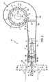
- Figs. 1-5 illustrate preferred embodiments of the apparatus of the present invention, generally designated 10.
- the apparatus 10 includes an inner chamber 15 defined by an outer housing 17.
- the apparatus 10 further includes a motor 12 having a horizontally-oriented output shaft 14.
- the output shaft 14 powers the fan 16 having a series of blades 18.
- the rotating blades 18 accelerate incoming air (shown by A arrows in Fig. 2) in the downstream direction (shown by B arrows in Figs. 1 and 2).
- a plurality of stationary, radially spaced straightening vanes 20 are positioned downstream of the fan 16 and serve to straighten the air flow that is propelled from the blades 18, and tend to remove rotational components in the air flow that are imparted by the blades 18.
- the straightening vanes 20 are preferably spaced evenly around the circumference of the blades 18.
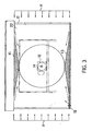
- the inlet assembly 22 includes two inlet chambers 24, 26, which are open to the ambient air. Air enters the apparatus 10 by means of these chambers 24, 26. Each chamber 24, 26 preferably has a filter 23, 25 to remove foreign particles from the air.
- the filters 23, 25 may be manufactured of a steel lattice having steel filter material interspersed therein, thereby preventing foreign objects from being drawn into the apparatus 10 by the rotating fan blades 18. As air enters into the inlet assembly 22, it is guided radially inwardly by a pair of guide surfaces 41, 43, as shown best in Fig. 3.
- the inlet assembly 22 further includes a vertical wall 30 and a converging inlet nozzle 32 which is generally elliptical in shape.
- the axis of the inlet nozzle 32 is generally perpendicular to the surface of the wall 30.
- This pressure distribution, or stagnation zone, 31 is centered on a portion of the wall 30 corresponding with the axis of the converging nozzle 32 and motor output shaft 14.
- the inlet chambers 24, 26, wall 30 and converging nozzle 32 operate so as to create this pressure distribution 31 on the centre of the wall 30 when the fan blades 18 are rotating.
- the pressure distribution 31 thus created aids in redirecting the air flow from a horizontal, generally radially inward directed flow, shown by A arrows, to a generally three-dimensional horizontally directed output flow, shown by B arrows, that is parallel to the output shaft 14.
- a boss 36 provides a converging section in which the air accelerates and moves radially outward, guiding the air towards the fan blades 18. The air flow is then propelled by the rotating fan blades 18 into the straightening vanes 20, after which it enters the fan diffuser section 40.
- the boss 36 continues into the diffuser section 40 and tapers inward to form a nacelle 42.
- the taper of the nacelle 42 is shaped to decrease the amount of turbulence created by air flowing off the surface of the nacelle 42.
- the gradual decrease in radius of the nacelle 42 in the downstream direction increases the cross-sectional area of the diffuser section 40 and inner chamber 15, thereby decelerating the air flow (shown by C arrows) in a controlled manner.
- the decrease in velocity of the air flow is accompanied by a corresponding increase in static energy which is important because the air flow velocity must be decreased in order to make it possible to turn the air in an efficient manner.
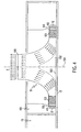
- transition diffuser 46 Once the air flow exits the diffuser section 40, it enters the transition diffuser 46.
- the transition diffuser 46 continues to increase the cross-sectional area of the inner chamber 15 while transforming the geometry of the inner chamber 15 from the cylindrical geometry dictated by the fan 16 to a preferred rectangular geometry.
- the transition diffuser 46 further decelerates the air flow and increases its static energy before the air flow is directed into the scroll 48.
- the path of the air is affected as follows.
- the air exiting the transition diffuser 46 is generally split into two air flows: roughly half the air enters the first chamber 50, and the remaining half enters the second chamber 52.
- Each chamber is shaped so that the cross-sectional area of the chamber decreases as the air flow continues in the downstream direction, thereby aiding in the distribution of the air flow relatively evenly around the periphery 55 of the nozzle 57.
- the entry of the air into the chambers 50, 52 is guided by a plurality of turning vanes 54, 56.
- the turning vanes 54, 56 are preferably curved pieces of sheet metal and are generally identical in shape.
- the air flow is guided in a direction around the outer walls of the chambers 50, 52 and towards the periphery 55 of the nozzle 57.
- the nozzle 57 is positioned so that it is suspended above the floor 60 of the scroll 48, thereby allowing the air flow around the periphery 55 of the nozzle 57 to enter underneath the bottom surface 49 of the nozzle 57 toward the central axis 59 of the nozzle 57 (shown by E arrows).
- the air flow is directed around the outer wall of the spiral 47 which curls around the central axis 59 of the nozzle 57. Since the cross-sectional area of the spiral 47 decreases proportionally with the radial movement around the outer periphery 55 of the nozzle 57, the air flow is proportionally and evenly directed under the bottom surface 49 of the nozzle 57 towards the central axis 59 of the nozzle 57. The remaining air, if any, on the completion of the air flow around the spiral 47 is directed to rejoin the incoming air flow into the scroll 48 at re-entry point 51.
- This hyperbolic spiral shape 47 for the scroll 48 is preferred because energy losses and air flow disturbances are less than those encountered using the above-mentioned symmetric chambers 50, 52.
- the bottom-most portions of the flow immediately enter into the nozzle 57 under the nozzle's 57 bottom surface 49.
- the upper portions of the air flow in the scroll 48 then drop down to replace the departed air flow.
- the flow of the air into the nozzle 57 (shown by E arrows) is aided by a plurality of nozzle guide vanes 53.
- the nozzle guide vanes 53 are shaped so as to direct the air flow into the nozzle 57 on a generally radially inward path towards the central axis 59 of the nozzle 57.
- the individual air flows impinge upon each other to form a generally conically shaped stagnation zone 62, which extends upwards from the floor 60 of the scroll, approximately at the central axis 59 of the nozzle 57 as best seen in Fig. 4, the stagnation zone 62 is responsible for redirecting air from a generally radially inward path to an axial flow, perpendicular to the floor 60 of the scroll 48.
- the curvature of the nozzle 57 is selected so as to create the appropriate stagnation zone 60 in the lower portion of the nozzle 57.
- the air exiting the nozzle 57 has a fairly uniform velocity profile with very little loss of velocity near the edges of the air flow.
- the air flow is controlled, less turbulent and is created more efficiently than in prior art vertically discharging wind tunnels.
Claims (13)
- Vertikale Windkanalvorrichtung mit einer ebenen horizontalen Stützfläche (60); einer konvergierenden Düse (57), die eine vertikale zentrale Achse (59) aufweist und mit einem Einlaß an ihrem unteren Ende und mit einem Auslaß an ihrem oberen Ende (65) versehen ist, wobei die Düse in einem Abstand von der genannten Stützfläche (60) angeordnet ist, um einen Eintritt für Luft in den genannten Einlaß zu bilden, wobei eine Schnecke (48) das Einlaßende der konvergierenden Düse (57) umschließt, wobei der Boden der Schnecke durch die genannte ebene horizontale Stützfläche (60) gebildet wird, wobei die genannte Vorrichtung mit einem Einlaßabschnitt (46) versehen ist, der einen Eintritt für Luft in die genannte Schnecke bildet, wobei die Vorrichtung mit einem Gebläseabschnitt (22, 20) versehen ist, mit einem Gebläse (16), das um eine horizontale Achse drehbar ist, um Luft entlang eines sich in horizontaler Richtung erstreckenden Diffusorabschnitts (40) zu dem genannten Einlaßabschnitt und von dort zu der genannten Schnecke zu lenken.
- Vorrichtung nach Anspruch 1, weiter umfassend eine Anzahl von Leitschaufeln (53), die auf der genannten Stützfläche (60) unterhalb des genannten Einlasses angeordnet sind, um die genannte Luftströmung entlang der genannten Stützfläche in einer im wesentlichen radial nach innen weisenden Richtung zu der genannten zentralen Achse (59) der Düse zu führen.
- Vorrichtung nach Anspruch 2, dadurch gekennzeichnet, daß der genannte Düseneinlaß eine kreisförmige Form aufweist und mit einem äußeren Umfang versehen ist, wobei der mittlere Punkt des genannten Düseneinlasses koaxial mit der genannten zentralen Achse der Düse ist.
- Vorrichtung nach Anspruch 3, dadurch gekennzeichnet, daß die genannte Schnecke in Form einer hyperbolischen Spirale geformt ist.
- Vorrichtung nach Anspruch 4, dadurch gekennzeichnet, daß die genannte, als hyperbolische Spirale geformte Schnecke eine äußere Wand aufweist, die um den äußeren Umfang des genannten Düseneinlasses herum positioniert ist, so daß die Querschnittsfläche zwischen der genannten äußeren Wand und dem äußeren Umfang des genannten Düseneinlasses im Verhältnis zu dem Winkel um die genannte zentrale Achse (59) der Düse ausgehend von dem genannten Einlaßabschnitt abnimmt, so daß die genannte Luftströmung entlang der Stützfläche gleichmäßig in Richtung auf die genannte zentrale Achse der Düse verteilt wird.
- Vorrichtung nach Anspruch 2, dadurch gekennzeichnet, daß die genannte Schnecke (48) aus zwei symmetrischen Kammern (50, 52) zusammengesetzt ist, wobei jede der genannten Kammern einen Einlaß, eine äußere Wand und eine Anzahl von Luftleitblechen (54, 56) aufweist, die in der Nähe des genannten Einlasses angeordnet sind.
- Vorrichtung nach Anspruch 5 oder Anspruch 6, dadurch gekennzeichnet, daß der genannte Einlaßabschnitt (46) in einer gemeinsamen Ebene mit der genannten Stützfläche (60) liegt, um eine Luftströmung zu der genannten Schnecke zu leiten.
- Vorrichtung nach Anspruch 7, dadurch gekennzeichnet, daß die Querschnittsfläche der genannten Kammern stromab von der genannten Luftströmung abnimmt, so daß dadurch eine gleichmäßige Verteilung des genannten Luftstroms in den genannten Düseneinlaß hinein erleichtert wird.
- Vorrichtung nach einem der vorangehenden Ansprüche, dadurch gekennzeichnet, daß das genannte Gebläse ein Mantelgebläse ist.
- Vorrichtung Anspruch 9, weiter umfassend einen Satz von Begradigungsschaufeln (20), die um den genannten Gebläseabschnitt herum angeordnet sind, um die genannte Luftströmung, die durch das Mantelgebläse erzeugt wird, zu begradigen.
- Vorrichtung nach Anspruch 10, dadurch gekennzeichnet, daß die genannten Begradigungsschaufeln (20) gleichmäßig in Umfangsrichtung um den genannten Gebläseabschnitt herum beabstandet angeordnet sind.
- Vorrichtung nach Anspruch 11, weiter umfassend eine Einlaßanordnung (22), die vor dem genannten Gebläseeinlaß positioniert ist und angeordnet ist, um Luft zu dem genannten Gebläseeinlaß zu leiten.
- Vorrichtung nach Anspruch 12, dadurch gekennzeichnet, daß die genannte Einlaßanordnung (22) obere und untere Führungsflächen (41, 43) aufweist, die in der genannten Einlaßanordnung (22) angeordnet sind und so eingerichtet sind, daß sie im Gebrauch Luft, die in die genannte Einlaßdüse in einer im wesentlichen radialen, einwärts gerichteten Richtung eintritt, zu dem genannten Gebläseeinlaß lenkt.
Applications Claiming Priority (2)
| Application Number | Priority Date | Filing Date | Title |
|---|---|---|---|
| US09/354,823 US6378361B1 (en) | 1999-07-16 | 1999-07-16 | Method and apparatus for creating a wind tunnel by redirecting an air flow ninety degrees |
| US354823 | 1999-07-16 |
Publications (3)
| Publication Number | Publication Date |
|---|---|
| EP1069420A2 EP1069420A2 (de) | 2001-01-17 |
| EP1069420A3 EP1069420A3 (de) | 2004-02-18 |
| EP1069420B1 true EP1069420B1 (de) | 2006-05-24 |
Family
ID=23395045
Family Applications (1)
| Application Number | Title | Priority Date | Filing Date |
|---|---|---|---|
| EP00305988A Expired - Lifetime EP1069420B1 (de) | 1999-07-16 | 2000-07-14 | Vertikaler Windkanal |
Country Status (10)
| Country | Link |
|---|---|
| US (1) | US6378361B1 (de) |
| EP (1) | EP1069420B1 (de) |
| JP (1) | JP2001065515A (de) |
| AR (1) | AR033496A1 (de) |
| AT (1) | ATE327501T1 (de) |
| DE (1) | DE60028138T2 (de) |
| DK (1) | DK1069420T3 (de) |
| ES (1) | ES2264660T3 (de) |
| HK (1) | HK1032626A1 (de) |
| NO (1) | NO320132B1 (de) |
Families Citing this family (16)
| Publication number | Priority date | Publication date | Assignee | Title |
|---|---|---|---|---|
| FR2791773B1 (fr) * | 1999-04-02 | 2001-06-15 | Sextant Avionique | Girouette destinee a s'orienter dans l'axe d'un ecoulement d'air ambiant |
| US6805558B1 (en) * | 2000-11-20 | 2004-10-19 | David Carl | Free fall and game simulator |
| AU2003269806A1 (en) * | 2002-03-25 | 2004-02-16 | Fleming And Associates, Inc. | Flow stabilizer for flow bench |
| AU2003218373A1 (en) * | 2002-03-26 | 2003-10-13 | Fleming And Associates, Inc. | Flow vector analyzer for flow bench |
| JP3721346B2 (ja) * | 2002-06-26 | 2005-11-30 | 株式会社ケーヒン | 遠心式送風機 |
| US8123836B2 (en) * | 2005-04-04 | 2012-02-28 | Telefonix, Incorporated | Air filtration and purification apparatus |
| US9689580B2 (en) * | 2005-04-04 | 2017-06-27 | Airistar Technologies | In line air filtration and purification apparatus |
| US10584885B2 (en) * | 2005-04-04 | 2020-03-10 | Airistar Technologies, Inc. | In line air filtration and purification apparatus |
| UA78399C2 (en) * | 2005-05-30 | 2007-03-15 | Viktor Borysovych Petruk | Wind channel |
| CN102853987A (zh) * | 2012-09-25 | 2013-01-02 | 南京航空航天大学 | 用于冰风洞中研究航空发动机整流罩积冰和防冰的试验器 |
| CN103623577B (zh) * | 2013-11-13 | 2015-07-08 | 芜湖华强文化科技产业有限公司 | 一种娱乐用风向模拟装置 |
| CN103623579B (zh) * | 2013-11-13 | 2015-01-21 | 芜湖华强文化科技产业有限公司 | 一种空中飞跃模拟用风向模拟装置 |
| CN103623576B (zh) * | 2013-11-13 | 2015-04-01 | 芜湖华强文化科技产业有限公司 | 一种娱乐用空中飞跃模拟系统 |
| US9945390B2 (en) * | 2014-07-31 | 2018-04-17 | Regal Beloit America, Inc. | Centrifugal blower and method of assembling the same |
| US10794409B2 (en) | 2017-09-29 | 2020-10-06 | Honda Motor Co., Ltd. | Turbulence generation system |
| CN112665815B (zh) * | 2020-12-28 | 2023-03-21 | 中国航天空气动力技术研究院 | 一种低噪声流场调试平台 |
Family Cites Families (30)
| Publication number | Priority date | Publication date | Assignee | Title |
|---|---|---|---|---|
| US1676984A (en) | 1928-07-10 | And fbank w | ||
| US1811364A (en) | 1930-06-07 | 1931-06-23 | Dimitry E Olshevsky | Wind tunnel for testing aeroplanes |
| US1940790A (en) | 1930-10-18 | 1933-12-26 | Walter S Diehl | Fluid conducting passage |
| US2448966A (en) | 1941-11-19 | 1948-09-07 | Elisha N Fales | Control of vortex flow by pressure waves |
| US2382999A (en) | 1943-10-06 | 1945-08-21 | Charles A Lee | Circulating water channel |
| US2593491A (en) | 1947-11-26 | 1952-04-22 | Harold E Saunders | Water tunnel |
| US3017769A (en) | 1956-11-14 | 1962-01-23 | Amrad Inc | Hydraulically simulated wind tunnel |
| US3484953A (en) | 1967-05-15 | 1969-12-23 | Ray H Norheim Jr | Apparatus for simulating free fall through air |
| US4150917A (en) | 1977-06-14 | 1979-04-24 | Westinghouse Electric Corp. | Rotor cooling for single and double axial flow turbines |
| FR2476761A1 (fr) | 1980-02-26 | 1981-08-28 | Tech Atlantique Centre | Aerogenerateur a captage statique omnidirectionnel |
| US4506849A (en) | 1980-03-28 | 1985-03-26 | Textron, Inc. | Helicopter rotor thrust ring |
| US4457509A (en) | 1981-03-05 | 1984-07-03 | Airflite, Inc. | Levitationarium for air flotation of humans |
| JPS60501353A (ja) * | 1981-10-20 | 1985-08-22 | エヴインガ−.リミテツド | スカイダイビングシミユレ−タ |
| FR2525287A1 (fr) | 1982-04-19 | 1983-10-21 | Bianchi Roger | Dispositif statique adaptable a tous les aeromoteurs pour ameliorer l'utilisation rationnelle et sure de l'energie eolienne |
| US4467020A (en) * | 1983-01-21 | 1984-08-21 | Yardngy Corporation | Rechargeable lead-hydrogen electrochemical cell |
| JPS59140972A (ja) * | 1983-01-31 | 1984-08-13 | Yamatake Honeywell Co Ltd | ケ−ジ弁 |
| JPS6172947A (ja) | 1984-09-18 | 1986-04-15 | Takasago Thermal Eng Co Ltd | クリ−ンル−ムの形成法およびこの方法に使用する空気調和設備ユニツト |
| US4818837A (en) | 1984-09-27 | 1989-04-04 | Regents Of The University Of Minnesota | Multiple arc plasma device with continuous gas jet |
| US4836689A (en) | 1986-02-27 | 1989-06-06 | Rosemount Inc. | Asymmetric purge air system for cleaning a lens |
| JPH01238884A (ja) * | 1988-03-22 | 1989-09-25 | Mitsui Eng & Shipbuild Co Ltd | スカイダイビング風洞 |
| JPH02263005A (ja) * | 1989-04-01 | 1990-10-25 | Satake Eng Co Ltd | 燃焼装置 |
| US5297930A (en) | 1991-12-31 | 1994-03-29 | Cornell Research Foundation, Inc. | Rotating stall suppression |
| JPH05223109A (ja) * | 1992-02-13 | 1993-08-31 | Hitachi Ltd | 整流ダクト |
| KR950006278Y1 (ko) | 1993-01-25 | 1995-08-05 | 이성환 | 대공간용 냉,난방 공조 환기장치 |
| US5435127A (en) | 1993-11-15 | 1995-07-25 | General Electric Company | Method and apparatus for boosting ram airflow to an ejection nozzle |
| US5454690A (en) | 1994-01-13 | 1995-10-03 | Shop Vac Corporation | Air flow housing |
| JPH08232893A (ja) * | 1995-02-22 | 1996-09-10 | Mitsubishi Heavy Ind Ltd | 遠心圧縮機 |
| JPH10318191A (ja) * | 1997-05-16 | 1998-12-02 | Mitsubishi Heavy Ind Ltd | 遠心圧縮機の吸込ケーシング |
| FR2766790B1 (fr) * | 1997-07-31 | 1999-10-08 | Abb Solyvent Ventec | Installation de vol libre pour la production artificielle d'un vent de sustentation |
| US6083110A (en) * | 1998-09-23 | 2000-07-04 | Sky Venture, Inc. | Vertical wind tunnel training device |
-
1999
- 1999-07-16 US US09/354,823 patent/US6378361B1/en not_active Expired - Lifetime
-
2000
- 2000-07-10 NO NO20003544A patent/NO320132B1/no not_active IP Right Cessation
- 2000-07-13 AR ARP000103609A patent/AR033496A1/es active IP Right Grant
- 2000-07-14 DK DK00305988T patent/DK1069420T3/da active
- 2000-07-14 ES ES00305988T patent/ES2264660T3/es not_active Expired - Lifetime
- 2000-07-14 EP EP00305988A patent/EP1069420B1/de not_active Expired - Lifetime
- 2000-07-14 DE DE60028138T patent/DE60028138T2/de not_active Expired - Lifetime
- 2000-07-14 AT AT00305988T patent/ATE327501T1/de not_active IP Right Cessation
- 2000-07-17 JP JP2000216510A patent/JP2001065515A/ja active Pending
-
2001
- 2001-03-06 HK HK01101608A patent/HK1032626A1/xx not_active IP Right Cessation
Also Published As
| Publication number | Publication date |
|---|---|
| EP1069420A3 (de) | 2004-02-18 |
| NO20003544L (no) | 2001-01-17 |
| ATE327501T1 (de) | 2006-06-15 |
| JP2001065515A (ja) | 2001-03-16 |
| DE60028138T2 (de) | 2007-03-15 |
| ES2264660T3 (es) | 2007-01-16 |
| EP1069420A2 (de) | 2001-01-17 |
| DK1069420T3 (da) | 2006-10-02 |
| NO320132B1 (no) | 2005-10-31 |
| NO20003544D0 (no) | 2000-07-10 |
| DE60028138D1 (de) | 2006-06-29 |
| HK1032626A1 (en) | 2001-07-27 |
| US6378361B1 (en) | 2002-04-30 |
| AR033496A1 (es) | 2003-12-26 |
Similar Documents
| Publication | Publication Date | Title |
|---|---|---|
| EP1069420B1 (de) | Vertikaler Windkanal | |
| CA1160095A (en) | Fume exhauster device | |
| US5749702A (en) | Fan for air handling system | |
| US4204799A (en) | Horizontal wind powered reaction turbine electrical generator | |
| US3312386A (en) | Fan | |
| US9636722B2 (en) | Exhaust fan assembly | |
| US2991927A (en) | Apparatus for moving fluids | |
| CN103270315B (zh) | 具有圆形入口及非旋转对称的出口的通风机扩散器 | |
| US4279569A (en) | Cross-flow turbine machine | |
| CN104302927B (zh) | 扩散器、具有这种扩散器的通风机以及具有这种通风机的设备 | |
| US6431974B1 (en) | Acoustic wind band | |
| US4457666A (en) | Apparatus and method for deriving energy from a moving gas stream | |
| LT4873B (lt) | Vėjo energijos įrenginys ir energijos transformavimo bei panaudojimo būdas | |
| EP0413406B1 (de) | Verfahren zum Bilden einer von einem Luftstrom umspülten Zone | |
| JPH06507693A (ja) | 並流から有用なエネルギーを発生させるための方法及び装置 | |
| US3778186A (en) | Radial diffuser | |
| US4648312A (en) | Apparatus for ventilating an enclosed area | |
| US5753811A (en) | Aerodynamic tunnel particularly suited for entertainment purposes | |
| US20030147745A1 (en) | Centrifugal fan | |
| CN110630454A (zh) | 电机及其轴系的换热装置、风力发电机组 | |
| US11143196B2 (en) | Fan system | |
| JPS61501463A (ja) | 流体羽根車ディフュ−ザと操作方法 | |
| US20230008558A1 (en) | Vertical-axis wind turbine | |
| US10336452B1 (en) | Drone with no external propeller blades | |
| US10006469B2 (en) | Diffuser and method of operating diffuser |
Legal Events
| Date | Code | Title | Description |
|---|---|---|---|
| PUAI | Public reference made under article 153(3) epc to a published international application that has entered the european phase |
Free format text: ORIGINAL CODE: 0009012 |
|
| AK | Designated contracting states |
Kind code of ref document: A2 Designated state(s): AT BE CH CY DE DK ES FI FR GB GR IE IT LI LU MC NL PT SE |
|
| AX | Request for extension of the european patent |
Free format text: AL;LT;LV;MK;RO;SI |
|
| PUAL | Search report despatched |
Free format text: ORIGINAL CODE: 0009013 |
|
| AK | Designated contracting states |
Kind code of ref document: A3 Designated state(s): AT BE CH CY DE DK ES FI FR GB GR IE IT LI LU MC NL PT SE |
|
| AX | Request for extension of the european patent |
Extension state: AL LT LV MK RO SI |
|
| RIC1 | Information provided on ipc code assigned before grant |
Ipc: 7G 01M 9/04 B Ipc: 7G 01M 9/02 A Ipc: 7A 63G 31/00 B Ipc: 7B 64D 23/00 B |
|
| 17P | Request for examination filed |
Effective date: 20040818 |
|
| AKX | Designation fees paid |
Designated state(s): AT BE CH CY DE DK ES FI FR GB GR IE IT LI LU MC NL PT SE |
|
| GRAP | Despatch of communication of intention to grant a patent |
Free format text: ORIGINAL CODE: EPIDOSNIGR1 |
|
| GRAS | Grant fee paid |
Free format text: ORIGINAL CODE: EPIDOSNIGR3 |
|
| GRAA | (expected) grant |
Free format text: ORIGINAL CODE: 0009210 |
|
| AK | Designated contracting states |
Kind code of ref document: B1 Designated state(s): AT BE CH CY DE DK ES FI FR GB GR IE IT LI LU MC NL PT SE |
|
| PG25 | Lapsed in a contracting state [announced via postgrant information from national office to epo] |
Ref country code: AT Free format text: LAPSE BECAUSE OF FAILURE TO SUBMIT A TRANSLATION OF THE DESCRIPTION OR TO PAY THE FEE WITHIN THE PRESCRIBED TIME-LIMIT Effective date: 20060524 Ref country code: BE Free format text: LAPSE BECAUSE OF FAILURE TO SUBMIT A TRANSLATION OF THE DESCRIPTION OR TO PAY THE FEE WITHIN THE PRESCRIBED TIME-LIMIT Effective date: 20060524 |
|
| REG | Reference to a national code |
Ref country code: GB Ref legal event code: FG4D |
|
| REG | Reference to a national code |
Ref country code: CH Ref legal event code: EP |
|
| REG | Reference to a national code |
Ref country code: IE Ref legal event code: FG4D |
|
| REF | Corresponds to: |
Ref document number: 60028138 Country of ref document: DE Date of ref document: 20060629 Kind code of ref document: P |
|
| PG25 | Lapsed in a contracting state [announced via postgrant information from national office to epo] |
Ref country code: IE Free format text: LAPSE BECAUSE OF NON-PAYMENT OF DUE FEES Effective date: 20060714 |
|
| PG25 | Lapsed in a contracting state [announced via postgrant information from national office to epo] |
Ref country code: MC Free format text: LAPSE BECAUSE OF NON-PAYMENT OF DUE FEES Effective date: 20060731 |
|
| REG | Reference to a national code |
Ref country code: HK Ref legal event code: GR Ref document number: 1032626 Country of ref document: HK |
|
| REG | Reference to a national code |
Ref country code: SE Ref legal event code: TRGR |
|
| REG | Reference to a national code |
Ref country code: CH Ref legal event code: NV Representative=s name: ISLER & PEDRAZZINI AG |
|
| REG | Reference to a national code |
Ref country code: DK Ref legal event code: T3 |
|
| PG25 | Lapsed in a contracting state [announced via postgrant information from national office to epo] |
Ref country code: PT Free format text: LAPSE BECAUSE OF FAILURE TO SUBMIT A TRANSLATION OF THE DESCRIPTION OR TO PAY THE FEE WITHIN THE PRESCRIBED TIME-LIMIT Effective date: 20061024 |
|
| ET | Fr: translation filed | ||
| REG | Reference to a national code |
Ref country code: ES Ref legal event code: FG2A Ref document number: 2264660 Country of ref document: ES Kind code of ref document: T3 |
|
| PLBE | No opposition filed within time limit |
Free format text: ORIGINAL CODE: 0009261 |
|
| STAA | Information on the status of an ep patent application or granted ep patent |
Free format text: STATUS: NO OPPOSITION FILED WITHIN TIME LIMIT |
|
| 26N | No opposition filed |
Effective date: 20070227 |
|
| REG | Reference to a national code |
Ref country code: CH Ref legal event code: PCAR Free format text: ISLER & PEDRAZZINI AG;POSTFACH 1772;8027 ZUERICH (CH) |
|
| PG25 | Lapsed in a contracting state [announced via postgrant information from national office to epo] |
Ref country code: GR Free format text: LAPSE BECAUSE OF FAILURE TO SUBMIT A TRANSLATION OF THE DESCRIPTION OR TO PAY THE FEE WITHIN THE PRESCRIBED TIME-LIMIT Effective date: 20060825 |
|
| PG25 | Lapsed in a contracting state [announced via postgrant information from national office to epo] |
Ref country code: LU Free format text: LAPSE BECAUSE OF NON-PAYMENT OF DUE FEES Effective date: 20060714 |
|
| PG25 | Lapsed in a contracting state [announced via postgrant information from national office to epo] |
Ref country code: CY Free format text: LAPSE BECAUSE OF FAILURE TO SUBMIT A TRANSLATION OF THE DESCRIPTION OR TO PAY THE FEE WITHIN THE PRESCRIBED TIME-LIMIT Effective date: 20060524 |
|
| PGFP | Annual fee paid to national office [announced via postgrant information from national office to epo] |
Ref country code: DK Payment date: 20110725 Year of fee payment: 12 Ref country code: FR Payment date: 20110805 Year of fee payment: 12 |
|
| PGFP | Annual fee paid to national office [announced via postgrant information from national office to epo] |
Ref country code: FI Payment date: 20110727 Year of fee payment: 12 Ref country code: ES Payment date: 20110726 Year of fee payment: 12 Ref country code: GB Payment date: 20110725 Year of fee payment: 12 Ref country code: SE Payment date: 20110727 Year of fee payment: 12 Ref country code: DE Payment date: 20110727 Year of fee payment: 12 |
|
| PGFP | Annual fee paid to national office [announced via postgrant information from national office to epo] |
Ref country code: NL Payment date: 20110728 Year of fee payment: 12 Ref country code: IT Payment date: 20110726 Year of fee payment: 12 |
|
| REG | Reference to a national code |
Ref country code: NL Ref legal event code: V1 Effective date: 20130201 |
|
| REG | Reference to a national code |
Ref country code: SE Ref legal event code: EUG |
|
| GBPC | Gb: european patent ceased through non-payment of renewal fee |
Effective date: 20120714 |
|
| REG | Reference to a national code |
Ref country code: DK Ref legal event code: EBP |
|
| REG | Reference to a national code |
Ref country code: FR Ref legal event code: ST Effective date: 20130329 |
|
| PG25 | Lapsed in a contracting state [announced via postgrant information from national office to epo] |
Ref country code: DE Free format text: LAPSE BECAUSE OF NON-PAYMENT OF DUE FEES Effective date: 20130201 Ref country code: GB Free format text: LAPSE BECAUSE OF NON-PAYMENT OF DUE FEES Effective date: 20120714 Ref country code: FR Free format text: LAPSE BECAUSE OF NON-PAYMENT OF DUE FEES Effective date: 20120731 Ref country code: FI Free format text: LAPSE BECAUSE OF NON-PAYMENT OF DUE FEES Effective date: 20120714 Ref country code: NL Free format text: LAPSE BECAUSE OF NON-PAYMENT OF DUE FEES Effective date: 20130201 Ref country code: SE Free format text: LAPSE BECAUSE OF NON-PAYMENT OF DUE FEES Effective date: 20120715 |
|
| REG | Reference to a national code |
Ref country code: DE Ref legal event code: R119 Ref document number: 60028138 Country of ref document: DE Effective date: 20130201 |
|
| PG25 | Lapsed in a contracting state [announced via postgrant information from national office to epo] |
Ref country code: IT Free format text: LAPSE BECAUSE OF NON-PAYMENT OF DUE FEES Effective date: 20120714 |
|
| PG25 | Lapsed in a contracting state [announced via postgrant information from national office to epo] |
Ref country code: DK Free format text: LAPSE BECAUSE OF NON-PAYMENT OF DUE FEES Effective date: 20120731 |
|
| REG | Reference to a national code |
Ref country code: ES Ref legal event code: FD2A Effective date: 20131021 |
|
| PG25 | Lapsed in a contracting state [announced via postgrant information from national office to epo] |
Ref country code: ES Free format text: LAPSE BECAUSE OF NON-PAYMENT OF DUE FEES Effective date: 20120715 |
|
| PGFP | Annual fee paid to national office [announced via postgrant information from national office to epo] |
Ref country code: CH Payment date: 20170727 Year of fee payment: 18 |
|
| REG | Reference to a national code |
Ref country code: CH Ref legal event code: PL |
|
| PG25 | Lapsed in a contracting state [announced via postgrant information from national office to epo] |
Ref country code: LI Free format text: LAPSE BECAUSE OF NON-PAYMENT OF DUE FEES Effective date: 20180731 Ref country code: CH Free format text: LAPSE BECAUSE OF NON-PAYMENT OF DUE FEES Effective date: 20180731 |