EP1008886A1 - Folded optical system having improved image isolation - Google Patents
Folded optical system having improved image isolation Download PDFInfo
- Publication number
- EP1008886A1 EP1008886A1 EP99116395A EP99116395A EP1008886A1 EP 1008886 A1 EP1008886 A1 EP 1008886A1 EP 99116395 A EP99116395 A EP 99116395A EP 99116395 A EP99116395 A EP 99116395A EP 1008886 A1 EP1008886 A1 EP 1008886A1
- Authority
- EP
- European Patent Office
- Prior art keywords
- light
- wave plate
- polarization
- beam splitter
- display
- Prior art date
- Legal status (The legal status is an assumption and is not a legal conclusion. Google has not performed a legal analysis and makes no representation as to the accuracy of the status listed.)
- Granted
Links
Images


Classifications
-
- G—PHYSICS
- G02—OPTICS
- G02B—OPTICAL ELEMENTS, SYSTEMS OR APPARATUS
- G02B27/00—Optical systems or apparatus not provided for by any of the groups G02B1/00 - G02B26/00, G02B30/00
- G02B27/01—Head-up displays
- G02B27/017—Head mounted
- G02B27/0172—Head mounted characterised by optical features
-
- G—PHYSICS
- G02—OPTICS
- G02B—OPTICAL ELEMENTS, SYSTEMS OR APPARATUS
- G02B27/00—Optical systems or apparatus not provided for by any of the groups G02B1/00 - G02B26/00, G02B30/00
- G02B27/28—Optical systems or apparatus not provided for by any of the groups G02B1/00 - G02B26/00, G02B30/00 for polarising
- G02B27/283—Optical systems or apparatus not provided for by any of the groups G02B1/00 - G02B26/00, G02B30/00 for polarising used for beam splitting or combining
-
- G—PHYSICS
- G02—OPTICS
- G02B—OPTICAL ELEMENTS, SYSTEMS OR APPARATUS
- G02B27/00—Optical systems or apparatus not provided for by any of the groups G02B1/00 - G02B26/00, G02B30/00
- G02B27/01—Head-up displays
- G02B27/0101—Head-up displays characterised by optical features
- G02B2027/0112—Head-up displays characterised by optical features comprising device for genereting colour display
- G02B2027/0116—Head-up displays characterised by optical features comprising device for genereting colour display comprising devices for correcting chromatic aberration
-
- G—PHYSICS
- G02—OPTICS
- G02B—OPTICAL ELEMENTS, SYSTEMS OR APPARATUS
- G02B5/00—Optical elements other than lenses
- G02B5/30—Polarising elements
Definitions
- the present invention relates to optical systems for viewing a display, and more particularly, to an optical system which utilizes a folded optical path to minimize the distance between the display and the viewer.
- Head-mounted computer displays may be viewed as "eye glasses" that are worn by the user to view images created by a computer or other image source. The image seen by each eye is generated on a display screen having a two dimensional array of pixels.
- optical systems based on reflectors are preferred since such systems provide high quality optical imaging at a cost that is much less than systems based on lenses.
- Prior art systems that combine reflective optics with short display to eye distances are known to the art. These systems typically utilize partially reflecting optical surfaces to fold the optical path so that the distance from the viewer's eye to the display is minimized. Such a system is described in U.S. Patent 5,644,436. For such systems to operate, the direct light emitted by the display must be blocked. Prior art systems typically utilize polarization filters and quarter wave plates to block the direct light from reaching the eye. Unfortunately, quarter wave plates only rotate the polarization vector of the light through precisely 90 degrees for specific wavelengths. Light having wavelengths that differ from the design wavelength is rotated either through slightly more than 90 degrees or slightly less than 90 degrees. Accordingly, these prior art systems do not block all of the light coming directly from the display and the viewer sees "ghost" images.
- the present invention is an optical collimating assembly for imaging light from a display.
- the optical assembly includes first and second linear polarization filters having polarization directions that are orthogonal to one another.
- a folded imaging assembly that includes a first beam splitter, a first 1 ⁇ 4 wave plate, and a second beam splitter is located between the polarization filters.
- a second 1 ⁇ 4 wave plate is also located between the polarization filters.
- the first 1 ⁇ 4 wave plate has a birefringence axis that is orthogonal to the birefringence axis of the second 1 ⁇ 4 wave plate.
- the 1 ⁇ 4 wave plates are constructed from the same birefringent material.
- One of the reflectors is preferably constructed from a material having a reflectivity that depends on the direction of linear polarization of light striking the beam splitter.
- FIG. 1 is a block diagram of a typical prior art folded optical assembly 20.
- Optical assembly 20 images light from display 12 into the eye of a viewer 14 using a spherical beam splitter 22 as the imaging element. Ideally, light traveling directly from display 12 to viewer 14 is blocked.
- Optical assembly 20 utilizes parallel polarization filters 21 and 26 with a polarization rotation of 90 degrees between them to prevent light traveling directly from display 12 from reaching viewer 14.
- Optical assembly 20 includes the parallel polarization filters 21 and 26, two 1 ⁇ 4 wave plates 23 and 25 and the beam splitter 24. The two 1 ⁇ 4 wave plates, 23 and 25, are located between the polarization filters.
- the beam splitter 24 is located between the 1 ⁇ 4 wave plates 23 and 25.
- the two 1 ⁇ 4 wave plates 23 and 25 collectively act as a 1 ⁇ 2 wave plate that rotates the polarization of the light coming directly from polarizer 21 by 90 degrees so that this light is blocked by the polarizer 26. Thus, light traveling directly from display 12 is prevented from reaching viewer 14.
- Optical assembly 20 For optical assembly 20 to operate properly, the light that is collimated by spherical beam splitter 22 must not undergo the 90 degree rotation of its polarization as did the light coming directly from display 12 to viewer 14.
- Optical assembly 20 utilizes the observation that circularly polarized light changes its direction of polarization upon reflection.
- Light collimated by beam splitter 22 passes through 1 ⁇ 4 wave plate 23 and leaves 1 ⁇ 4 wave plate 23 circularly polarized. Assume the polarization of this light is right handed. The polarization of this light is then changed to left handed upon reflection from beam splitter 24.
- the light Upon passing again through 1 ⁇ 4 wave plate 23, the light becomes linearly polarized, but the direction of polarization is rotated by 90 degrees relative to the direction of polarization imposed by the polarizer 21.
- a 1 ⁇ 4 wave plate is a birefringent material where the thickness is chosen such that there is a phase retardation of ⁇ /2 between the fast and slow polarizations. If the light source's polarization axis is aligned to 45° between the slow and fast axis of the wave plate, left-hand circularly-polarized light emerges. If the angle is -45°, the output is right-hand circularly-polarized light.
- any axis that defines the orientation of the fast axis will be referred to as the "birefringence axis".
- the thickness of the 1 ⁇ 4 wave plate can only be chosen correctly for a particular wavelength in the optical portion of the spectrum. At other wavelengths, a small error occurs in the degree of retardation of the slow component. This error leads to a change in the polarization of the light passing directly from display 12 to viewer 14 between the polarization filters. Since the polarization filters only completely block light if there is an exact 90° rotation in polarization between them, a small fraction of the light leaving display 12 will reach the viewer. This results in the viewer seeing a ghost image that varies in intensity with color.
- the present invention avoids the ghosting problems associated with prior art systems by utilizing an arrangement of 1 ⁇ 4 wave plates in which the second 1 ⁇ 4 wave plate reverses the action of the first 1 ⁇ 4 wave plate. For example, if the first 1 ⁇ 4 wave plate provides a retardation of ⁇ /2 between the two component polarizations of the light signal, then the second 1 ⁇ 4 wave plate provides a retardation of - ⁇ /2 between the components. This is accomplished by aligning the 1 ⁇ 4 wave plates such that the birefringence axis of the first 1 ⁇ 4 wave plate is rotated by 90° relative to the birefringence axis of the second 1 ⁇ 4 wave plate.
- the 1 ⁇ 4 wave plates are constructed from the same material.
- the design wavelength i.e., the wavelength for which the retardation is precisely ⁇ /2. If the first 1 ⁇ 4 wave plate provides a retardation of less than ⁇ /2 than the second 1 ⁇ 4 wave plate will also provide a canceling retardation of the same amount. Hence, the polarization of light passing through the two 1 ⁇ 4 wave plates will remain unchanged independent of the actual retardation provided by the wave plates.
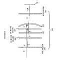
- FIG 2 is a cross-sectional view of a folded optical assembly 100 according to the present invention for collimating light from a display 12.
- the light leaving display 12 is unpolarized. Accordingly, the light leaving display 12 may be viewed as originating from two linear polarized sources, one generating light of a polarization denoted by "S" in the figure and one generating light of a polarization "P", where P is orthogonal to S.
- a first polarization filter 101 is set to remove the light of polarization P, leaving the light of polarization S.
- a first 1 ⁇ 4 wave plate 102 converts this light into right-handed circularly polarized light, denote by "R" in the figure.
- Wave plate 104 converts the right-handed circularly polarized light back to linear polarized light having a polarization in the S direction.
- This light strikes a planar beam splitter 105 which reflects a portion of the light back toward spherical beam splitter 103.
- polarization filter 106 which is set to block linearly polarized light having a polarization in the S direction. This is the light that comes directly from the display.
- wave plate 104 is oriented such that it reverses the action of wave plate 102. Hence, all of the light from the display is blocked independent of the wavelength of the light.
- the light that is reflected by beam splitter 105 passes back through 1 ⁇ 4 wave plate 104 and is converted back to right-handed circularly polarized light.
- This light is reflected by spherical beam splitter 103.
- circularly polarized light reverses polarization direction; hence, the light leaving spherical beam splitter 103 is left-handed circularly polarized light as indicated by the "L" in the figure.
- This light passes through 1 ⁇ 4 wave plate 104 and is converted back to linearly polarized light.
- the direction of polarization is now P.
- the compound effect of the imperfect 1 ⁇ 4 wave plates adds a little S polarization to this light, but this will only slightly decrease the throughput.
- Half of this light passes through beam splitter 105 and leaves the assembly via polarization filter 106, which is set to pass light having a polarization in the P direction.
- the other half of the light is reflected again from reflector 103; however, this light will return with an S polarization, and hence, any light escaping the next reflection at beam splitter 105 will be blocked by filter 106. Accordingly, only the portion of the remaining light that undergoes two reflections from beam splitter 103 can escape.
- Each reflection from a beam splitter reduces the light intensity by a factor of two.
- the light reflected from spherical reflector 103 will no longer be collimated for viewing by the observer.
- the light that does not escape after the first reflection from reflector 103 is reduced in intensity by a factor of 16 and defocused. This background is sufficiently diffuse and reduced in intensity to be acceptable to a human viewer of display 12.
- FIG. 3 is a cross-sectional view of another embodiment of a folded optical assembly according to the present invention.
- Optical assembly 200 differs from optical assembly 100 shown in Figure 2 in the placement of the 1 ⁇ 4 wave plate that compensates for the action of the 1 ⁇ 4 wave plate between the two beam splitters.
- the compensating 1 ⁇ 4 wave plate was located before the beam splitters, i.e., wave plate 102.
- the compensating wave plate, 1 ⁇ 4 wave plate 202 is located after the beam splitters.
- the 1 ⁇ 4 wave plates are arranged such that the slow optical axes of the wave plates are orthogonal to one another.
- the above described embodiments of the present invention utilize a spherical beam splitter and a planar beam splitter with a 1 ⁇ 4 wave plate located therebetween.
- any arrangement of two beam splitters that images the light from the display may be utilized.
- the preferred embodiment of the present invention utilizes a planar and a spherical beam splitter because of the ease with which these reflectors are generated.
- the above-described embodiments of the present invention utilize partially reflecting surfaces to construct the beam splitters. If half-silvered surfaces are utilized, one half of the light is lost on each reflection. This leads to a substantial decrease in the brightness of the display. This light loss can be substantially reduced by utilizing a partially reflecting surface whose reflectance depends on the polarization of the light incident thereon.
- the imaging assembly of the present invention depends on a combination of two reflectors with a 1 ⁇ 4 wave plate located between the two reflectors. One of the reflectors reflects circularly polarized light, and the other reflects linearly polarized light. For example, in optical assembly 100, reflector 105 reflects linearly polarized light, and reflector 103 reflects circularly polarized light. In optical assembly 200, reflector 205 reflects circularly polarized light, and reflector 203 reflects linearly polarized light.
- reflector 105 is constructed from a material that reflects light of one linear polarization and transmits light of the other linear polarization.
- DBEF DUAL BRIGHTNESS ENHANCEMENT FILM
- reflector 105 is constructed such that S polarized light is reflected and P polarized light is transmitted.
- all of the light striking reflector 105 is reflected toward reflector 103.
- Half of the light striking reflector 103 is reflected back to the viewer. All of this light will reach the viewer, since all of the light reflected by reflector 103 will be P polarized when it reaches reflector 105.
- both beam splitters can be curved and the curvature does not need to be spherical.
Abstract
Description
- The present invention relates to optical systems for viewing a display, and more particularly, to an optical system which utilizes a folded optical path to minimize the distance between the display and the viewer.
- To simplify the following discussion, the present invention will be discussed in terms of displays utilized in head mounted computer displays; however, it will be apparent to those skilled in the art from the following discussion that the present invention may be applied to other types of displays. Head-mounted computer displays may be viewed as "eye glasses" that are worn by the user to view images created by a computer or other image source. The image seen by each eye is generated on a display screen having a two dimensional array of pixels.
- It is advantageous to minimize the distance between the display and the eye of the viewer to minimize the portion of the display that extends from the viewer's face. Large overhanging displays are uncomfortable to wear. In addition, optical systems based on reflectors are preferred since such systems provide high quality optical imaging at a cost that is much less than systems based on lenses.
- Prior art systems that combine reflective optics with short display to eye distances are known to the art. These systems typically utilize partially reflecting optical surfaces to fold the optical path so that the distance from the viewer's eye to the display is minimized. Such a system is described in U.S. Patent 5,644,436. For such systems to operate, the direct light emitted by the display must be blocked. Prior art systems typically utilize polarization filters and quarter wave plates to block the direct light from reaching the eye. Unfortunately, quarter wave plates only rotate the polarization vector of the light through precisely 90 degrees for specific wavelengths. Light having wavelengths that differ from the design wavelength is rotated either through slightly more than 90 degrees or slightly less than 90 degrees. Accordingly, these prior art systems do not block all of the light coming directly from the display and the viewer sees "ghost" images.
- Broadly, it is the object of the present invention to provide an improved folded optical system based on reflective optical imaging elements.
- It is a further object of the present invention to provide an optical system in which light from the display being imaged is blocked from reaching the viewer's eye independent of the wavelength of the light.
- These and other objects of the present invention will become apparent to those skilled in the art from the following detailed description of the invention and the accompanying drawings.
- The present invention is an optical collimating assembly for imaging light from a display. The optical assembly includes first and second linear polarization filters having polarization directions that are orthogonal to one another. A folded imaging assembly that includes a first beam splitter, a first ¼ wave plate, and a second beam splitter is located between the polarization filters. A second ¼ wave plate is also located between the polarization filters. The first ¼ wave plate has a birefringence axis that is orthogonal to the birefringence axis of the second ¼ wave plate. In the preferred embodiment of the present invention, the ¼ wave plates are constructed from the same birefringent material. One of the reflectors is preferably constructed from a material having a reflectivity that depends on the direction of linear polarization of light striking the beam splitter.
-
- Figure 1 is a cross-sectional view of a prior art folded optical imaging assembly.
- Figure 2 is a cross-sectional view of one embodiment of a folded optical imaging assembly according to the present invention.
- Figure 3 is a cross-sectional view of another embodiment of a folded optical imaging assembly according to the present invention.
-
- The manner in which the present invention gains its advantages may be more easily understood with reference to Figure 1 which is a block diagram of a typical prior art folded
optical assembly 20.Optical assembly 20 images light fromdisplay 12 into the eye of aviewer 14 using aspherical beam splitter 22 as the imaging element. Ideally, light traveling directly fromdisplay 12 toviewer 14 is blocked.Optical assembly 20 utilizesparallel polarization filters 21 and 26 with a polarization rotation of 90 degrees between them to prevent light traveling directly fromdisplay 12 from reachingviewer 14.Optical assembly 20 includes theparallel polarization filters 21 and 26, two ¼wave plates beam splitter 24. The two ¼ wave plates, 23 and 25, are located between the polarization filters. Thebeam splitter 24 is located between the ¼wave plates wave plates polarizer 21 by 90 degrees so that this light is blocked by the polarizer 26. Thus, light traveling directly fromdisplay 12 is prevented from reachingviewer 14. - For
optical assembly 20 to operate properly, the light that is collimated byspherical beam splitter 22 must not undergo the 90 degree rotation of its polarization as did the light coming directly fromdisplay 12 toviewer 14.Optical assembly 20 utilizes the observation that circularly polarized light changes its direction of polarization upon reflection. Light collimated bybeam splitter 22 passes through ¼wave plate 23 and leaves ¼wave plate 23 circularly polarized. Assume the polarization of this light is right handed. The polarization of this light is then changed to left handed upon reflection frombeam splitter 24. Upon passing again through ¼wave plate 23, the light becomes linearly polarized, but the direction of polarization is rotated by 90 degrees relative to the direction of polarization imposed by thepolarizer 21. When this light is reflected byspherical beam splitter 22, the direction of polarization is not changed. This light passes once more through ¼wave plate 23, where its polarization is converted to left-handed circular polarization. Since the polarization of this light is left handed, unlike that of the light coming directly fromdisplay 12, which is right handed, ¼wave plate 25 converts this light to linearly-polarized light. However, the direction of polarization of this linearly-polarized light has not undergone the 90 degree rotation undergone by the direction of polarization of the light coming directly fromdisplay 12. Hence, this light will pass through polarization filter 26. - The light passing directly from
display 12 without reflection passes through both ¼ wave plates. If the ¼ wave plates behave in an ideal manner, they will act as a ½ wave plate and the direction of polarization of the light will rotate by 90°. A ¼ wave plate is a birefringent material where the thickness is chosen such that there is a phase retardation of π/2 between the fast and slow polarizations. If the light source's polarization axis is aligned to 45° between the slow and fast axis of the wave plate, left-hand circularly-polarized light emerges. If the angle is -45°, the output is right-hand circularly-polarized light. To simplify the following discussion, any axis that defines the orientation of the fast axis will be referred to as the "birefringence axis". - It should be noted that the thickness of the ¼ wave plate can only be chosen correctly for a particular wavelength in the optical portion of the spectrum. At other wavelengths, a small error occurs in the degree of retardation of the slow component. This error leads to a change in the polarization of the light passing directly from
display 12 toviewer 14 between the polarization filters. Since the polarization filters only completely block light if there is an exact 90° rotation in polarization between them, a small fraction of thelight leaving display 12 will reach the viewer. This results in the viewer seeing a ghost image that varies in intensity with color. - The present invention avoids the ghosting problems associated with prior art systems by utilizing an arrangement of ¼ wave plates in which the second ¼ wave plate reverses the action of the first ¼ wave plate. For example, if the first ¼ wave plate provides a retardation of π/2 between the two component polarizations of the light signal, then the second ¼ wave plate provides a retardation of -π/2 between the components. This is accomplished by aligning the ¼ wave plates such that the birefringence axis of the first ¼ wave plate is rotated by 90° relative to the birefringence axis of the second ¼ wave plate.
- In the preferred embodiment of the present invention, the ¼ wave plates are constructed from the same material. Consider light of a wavelength that is different from the design wavelength, i.e., the wavelength for which the retardation is precisely π/2. If the first ¼ wave plate provides a retardation of less than π/2 than the second ¼ wave plate will also provide a canceling retardation of the same amount. Hence, the polarization of light passing through the two ¼ wave plates will remain unchanged independent of the actual retardation provided by the wave plates.
- Refer now to Figure 2, which is a cross-sectional view of a folded
optical assembly 100 according to the present invention for collimating light from adisplay 12. For the purposes of this discussion, it will be assumed that thelight leaving display 12 is unpolarized. Accordingly, thelight leaving display 12 may be viewed as originating from two linear polarized sources, one generating light of a polarization denoted by "S" in the figure and one generating light of a polarization "P", where P is orthogonal to S. Afirst polarization filter 101 is set to remove the light of polarization P, leaving the light of polarization S. A first ¼wave plate 102 converts this light into right-handed circularly polarized light, denote by "R" in the figure. This light passes through aspherical beam splitter 103 and a second ¼wave plate 104.Wave plate 104 converts the right-handed circularly polarized light back to linear polarized light having a polarization in the S direction. This light strikes aplanar beam splitter 105 which reflects a portion of the light back towardspherical beam splitter 103. - The remainder of the light 111
strikes polarization filter 106 which is set to block linearly polarized light having a polarization in the S direction. This is the light that comes directly from the display. As noted above,wave plate 104 is oriented such that it reverses the action ofwave plate 102. Hence, all of the light from the display is blocked independent of the wavelength of the light. - The light that is reflected by
beam splitter 105 passes back through ¼wave plate 104 and is converted back to right-handed circularly polarized light. This light is reflected byspherical beam splitter 103. Upon reflection, circularly polarized light reverses polarization direction; hence, the light leavingspherical beam splitter 103 is left-handed circularly polarized light as indicated by the "L" in the figure. This light passes through ¼wave plate 104 and is converted back to linearly polarized light. However, the direction of polarization is now P. The compound effect of the imperfect ¼ wave plates adds a little S polarization to this light, but this will only slightly decrease the throughput. Half of this light passes throughbeam splitter 105 and leaves the assembly viapolarization filter 106, which is set to pass light having a polarization in the P direction. - The other half of the light is reflected again from
reflector 103; however, this light will return with an S polarization, and hence, any light escaping the next reflection atbeam splitter 105 will be blocked byfilter 106. Accordingly, only the portion of the remaining light that undergoes two reflections frombeam splitter 103 can escape. Each reflection from a beam splitter reduces the light intensity by a factor of two. In addition, the light reflected fromspherical reflector 103 will no longer be collimated for viewing by the observer. Hence, the light that does not escape after the first reflection fromreflector 103 is reduced in intensity by a factor of 16 and defocused. This background is sufficiently diffuse and reduced in intensity to be acceptable to a human viewer ofdisplay 12. - Refer now to Figure 3 which is a cross-sectional view of another embodiment of a folded optical assembly according to the present invention. To simplify the following discussion, those elements of
assembly 200 that serve the same function as elements shown in Figure 2 have been given numerical designations that differ by 100 from those used in Figure 2.Optical assembly 200 differs fromoptical assembly 100 shown in Figure 2 in the placement of the ¼ wave plate that compensates for the action of the ¼ wave plate between the two beam splitters. Inassembly 100 the compensating ¼ wave plate was located before the beam splitters, i.e.,wave plate 102. Inassembly 200, the compensating wave plate, ¼wave plate 202, is located after the beam splitters. Once again, the ¼ wave plates are arranged such that the slow optical axes of the wave plates are orthogonal to one another. - The above described embodiments of the present invention utilize a spherical beam splitter and a planar beam splitter with a ¼ wave plate located therebetween. However, it will be obvious to those skilled in the art from the preceding discussion that any arrangement of two beam splitters that images the light from the display may be utilized. The preferred embodiment of the present invention utilizes a planar and a spherical beam splitter because of the ease with which these reflectors are generated.
- The above-described embodiments of the present invention utilize partially reflecting surfaces to construct the beam splitters. If half-silvered surfaces are utilized, one half of the light is lost on each reflection. This leads to a substantial decrease in the brightness of the display. This light loss can be substantially reduced by utilizing a partially reflecting surface whose reflectance depends on the polarization of the light incident thereon. The imaging assembly of the present invention depends on a combination of two reflectors with a ¼ wave plate located between the two reflectors. One of the reflectors reflects circularly polarized light, and the other reflects linearly polarized light. For example, in
optical assembly 100,reflector 105 reflects linearly polarized light, andreflector 103 reflects circularly polarized light. Inoptical assembly 200,reflector 205 reflects circularly polarized light, andreflector 203 reflects linearly polarized light. - If the reflector that reflects linearly polarized light is constructed from a material that reflects light of one linear polarization and transmits light of the other linear polarization, a factor of 4 in the intensity of the light reaching the viewer is obtained. For example, in
assembly 100,reflector 105 is constructed from a material that reflects light of one polarization while transmitting light of the orthogonal polarization. Such materials are known to the art. For example 3M markets such a material under the trade name DUAL BRIGHTNESS ENHANCEMENT FILM (DBEF). In the preferred embodiment of the present invention,reflector 105 is constructed such that S polarized light is reflected and P polarized light is transmitted. Hence, all of the lightstriking reflector 105 is reflected towardreflector 103. Half of the lightstriking reflector 103 is reflected back to the viewer. All of this light will reach the viewer, since all of the light reflected byreflector 103 will be P polarized when it reachesreflector 105. - The above-described embodiments of the present invention have utilized planar and spherical beam splitters. However, other geometries can be utilized without deviating from the teachings of the present invention. For example, both beam splitters can be curved and the curvature does not need to be spherical.
- Various modifications to the present invention will become apparent to those skilled in the art from the foregoing description and accompanying drawings. Accordingly, the present invention is to be limited solely by the scope of the following claims.
Claims (5)
- An optical imaging assembly[100,200] for imaging light from a display, said assembly comprising: a first linear polarization filter[101, 201] for passing light polarized in a first direction; a second liner polarization filter[106, 206] for passing light polarized in a second direction, said second direction being orthogonal to said first direction; a folded imaging assembly comprising a first beam splitter[105, 205], a first ¼ wave plate[104, 204], and a second beam splitter[103, 203]; and a second ¼ wave plate[102, 202], wherein said folded imaging assembly and said second ¼ wave plate[102, 202] are located between said first and second linear polarization filters, and wherein said first ¼ wave plate[104, 204] has a birefringence axis that is orthogonal to the birefringence axis of said second ¼ wave plate[102, 204].
- The optical imaging assembly[100,200] of Claim 1 wherein one of said first and second beam splitters comprises a material having a reflectivity that depends on the direction of linear polarization of light striking said beam splitter.
- The optical imaging assembly[100,200] of Claim 1 or 2 wherein said first beam splitter[105, 205] comprises a partially reflecting planar surface and said second beam splitter[103, 203] comprises a partially reflecting curved surface.
- The optical imaging assembly[100,200] of Claim 3 wherein said curved surface is spherical.
- The optical imaging assembly[100,200] of one of Claims 1 to 4 wherein said first and second ¼ wave plates comprise a layer of the same bi-refringent material.
Applications Claiming Priority (2)
| Application Number | Priority Date | Filing Date | Title |
|---|---|---|---|
| US209572 | 1994-03-10 | ||
| US09/209,572 US6271969B1 (en) | 1998-12-11 | 1998-12-11 | Folded optical system having improved image isolation |
Publications (2)
| Publication Number | Publication Date |
|---|---|
| EP1008886A1 true EP1008886A1 (en) | 2000-06-14 |
| EP1008886B1 EP1008886B1 (en) | 2005-01-12 |
Family
ID=22779308
Family Applications (1)
| Application Number | Title | Priority Date | Filing Date |
|---|---|---|---|
| EP99116395A Expired - Lifetime EP1008886B1 (en) | 1998-12-11 | 1999-08-20 | Folded optical system having improved image isolation |
Country Status (4)
| Country | Link |
|---|---|
| US (1) | US6271969B1 (en) |
| EP (1) | EP1008886B1 (en) |
| JP (1) | JP4408159B2 (en) |
| DE (1) | DE69923152T2 (en) |
Cited By (11)
| Publication number | Priority date | Publication date | Assignee | Title |
|---|---|---|---|---|
| EP1024388A2 (en) * | 1999-01-28 | 2000-08-02 | Kaiser Electro-Optics, Inc. | Compact collimating apparatus |
| WO2002063373A2 (en) * | 2000-12-29 | 2002-08-15 | Honeywell International Inc. | Beam folding with polarizing splitters |
| WO2002088817A1 (en) * | 2001-04-26 | 2002-11-07 | Raytheon Company | Wide-angle collimating optical device |
| EP1498751A1 (en) * | 2002-04-23 | 2005-01-19 | Nitto Denko Corporation | Polarizer, polarization light source and image displayunit using them |
| EP1498770A1 (en) * | 2002-04-24 | 2005-01-19 | Nitto Denko Corporation | Viewing angle magnification liquid crystal display unit |
| WO2006111933A1 (en) * | 2005-04-22 | 2006-10-26 | Koninklijke Philips Electronics N.V. | Variable focus lens |
| WO2017136043A1 (en) * | 2016-02-04 | 2017-08-10 | Google Inc. | Compact near-eye display optics for higher optical performance |
| US9977246B2 (en) | 2014-03-18 | 2018-05-22 | 3M Innovative Properties Company | Low profile image combiner for near-eye displays |
| US10545347B2 (en) | 2017-02-23 | 2020-01-28 | Google Llc | Compact eye tracking using folded display optics |
| WO2020215782A1 (en) * | 2019-04-24 | 2020-10-29 | 歌尔股份有限公司 | Lens assembly, and optical system and head-mounted device with same |
| US11054648B2 (en) | 2016-02-04 | 2021-07-06 | Google Llc | Compact near-eye display optics for higher optical performance |
Families Citing this family (31)
| Publication number | Priority date | Publication date | Assignee | Title |
|---|---|---|---|---|
| KR20010073072A (en) * | 1999-07-02 | 2001-07-31 | 요트.게.아. 롤페즈 | Head-mounted display |
| WO2001075508A1 (en) * | 2000-03-31 | 2001-10-11 | Koninklijke Philips Electronics N.V. | Head-mounted display |
| CN1639883A (en) * | 2002-03-06 | 2005-07-13 | 皇家飞利浦电子股份有限公司 | Electronic display device |
| CN100399075C (en) * | 2002-04-23 | 2008-07-02 | 日东电工株式会社 | Polarizing element, polarizing light source and picture display device using them |
| US6853491B1 (en) * | 2003-11-26 | 2005-02-08 | Frank Ruhle | Collimating optical member for real world simulation |
| US7242524B2 (en) * | 2003-11-25 | 2007-07-10 | Pc Mirage, Llc | Optical system for forming a real image in space |
| US7133207B2 (en) * | 2004-02-18 | 2006-11-07 | Icuiti Corporation | Micro-display engine |
| US20090052838A1 (en) * | 2004-03-22 | 2009-02-26 | Mcdowall Ian | Electrically controlled optical elements and method |
| US20070273970A1 (en) * | 2006-05-26 | 2007-11-29 | Creative Display Systems, Llc | Wide field of view, compact collimating apparatus |
| GB2449682A (en) * | 2007-06-01 | 2008-12-03 | Sharp Kk | Optical system for converting a flat image to a non-flat image |
| GB2465786A (en) * | 2008-11-28 | 2010-06-02 | Sharp Kk | An optical system for varying the perceived shape of a display surface |
| JP6216100B1 (en) | 2014-10-24 | 2017-10-18 | イメージン コーポレイション | Microdisplay-based immersive headset |
| WO2016109244A1 (en) | 2014-12-31 | 2016-07-07 | 3M Innovative Properties Company | Compact projection systems and related components |
| KR102634148B1 (en) | 2015-03-16 | 2024-02-05 | 매직 립, 인코포레이티드 | Methods and system for diagnosing and treating health ailments |
| KR20170063806A (en) | 2015-09-03 | 2017-06-08 | 쓰리엠 이노베이티브 프로퍼티즈 컴파니 | Magnifying device |
| US10095036B2 (en) * | 2016-02-04 | 2018-10-09 | Google Llc | Compact near-eye display optics |
| WO2017161488A1 (en) * | 2016-03-21 | 2017-09-28 | 深圳多哚新技术有限责任公司 | Short-distance optical magnification module, glasses, helmet and vr system |
| JP2017187685A (en) * | 2016-04-07 | 2017-10-12 | 日本化薬株式会社 | Light reflection film having curved surface shape and method for manufacturing the same, and light control film, optical film, functional glass and head-up display using the light reflection film |
| US10197802B2 (en) * | 2016-07-29 | 2019-02-05 | Intevac, Inc. | Biocular compact collimation apparatus |
| US10203489B2 (en) * | 2016-08-02 | 2019-02-12 | Apple Inc. | Optical system for head-mounted display |
| JP7027035B2 (en) * | 2016-11-15 | 2022-03-01 | 日東電工株式会社 | Set of optical communication device and polarizing plate |
| KR102601052B1 (en) | 2017-02-23 | 2023-11-09 | 매직 립, 인코포레이티드 | Display system with variable power reflector |
| JP6984261B2 (en) | 2017-09-14 | 2021-12-17 | セイコーエプソン株式会社 | Virtual image display device |
| US11054622B1 (en) | 2017-11-20 | 2021-07-06 | Facebook Technologies, Llc | Folded viewing optics with an optical retarder on a simple surface |
| CN110007461A (en) * | 2017-12-30 | 2019-07-12 | 深圳多哚新技术有限责任公司 | Optical system |
| WO2019154426A1 (en) * | 2018-02-12 | 2019-08-15 | 杭州太若科技有限公司 | Augmented reality device and optical system used therein |
| DE102018204506A1 (en) * | 2018-03-23 | 2019-09-26 | BSH Hausgeräte GmbH | Optical arrangement for improving the display quality of a display |
| US11022784B1 (en) * | 2018-08-17 | 2021-06-01 | Facebook Technologies, Llc | Use of folded optics to reduce volume in a virtual-reality system |
| US11372239B1 (en) | 2018-11-01 | 2022-06-28 | Facebook Technologies, Llc | Enabling eye tracking in pancake lens optics |
| US10890776B1 (en) * | 2019-02-19 | 2021-01-12 | Facebook Technologies, Llc | Pancake lens ghosting mitigation |
| US11604350B2 (en) | 2020-02-28 | 2023-03-14 | Sharp Kabushiki Kaisha | Polarization mirror HMD with increased brightness |
Citations (6)
| Publication number | Priority date | Publication date | Assignee | Title |
|---|---|---|---|---|
| US4653875A (en) * | 1984-11-02 | 1987-03-31 | Hines Stephen P | Infinity display apparatus using cylindrical beam-splitters |
| EP0351967A2 (en) * | 1988-07-06 | 1990-01-24 | Kaiser Aerospace And Electronics Corporation | Improved optical combiner collimating apparatus |
| EP0718645A2 (en) * | 1994-12-19 | 1996-06-26 | Sharp Kabushiki Kaisha | Optical device and head-mounted display using said optical device |
| WO1997001774A1 (en) * | 1995-06-26 | 1997-01-16 | Minnesota Mining And Manufacturing Company | High efficiency optical devices |
| US5644436A (en) * | 1994-03-18 | 1997-07-01 | Olympus Optical Co., Ltd. | Concentric optical system |
| EP0803756A1 (en) * | 1996-04-24 | 1997-10-29 | Sharp Kabushiki Kaisha | Viewing device for head mounted display |
Family Cites Families (4)
| Publication number | Priority date | Publication date | Assignee | Title |
|---|---|---|---|---|
| US4847693A (en) * | 1987-04-24 | 1989-07-11 | Ultramatrix, Inc. | Composite process video and motion picture photography system and method |
| US5864326A (en) * | 1992-02-07 | 1999-01-26 | I-O Display Systems Llc | Depixelated visual display |
| GB2320713B (en) | 1995-09-19 | 1999-10-20 | Exide Corp | Process for destroying hazardous materials |
| CN1132136C (en) * | 1995-12-22 | 2003-12-24 | 皇家菲利浦电子有限公司 | Picture display device with two microlens arrays |
-
1998
- 1998-12-11 US US09/209,572 patent/US6271969B1/en not_active Expired - Lifetime
-
1999
- 1999-08-20 DE DE69923152T patent/DE69923152T2/en not_active Expired - Lifetime
- 1999-08-20 EP EP99116395A patent/EP1008886B1/en not_active Expired - Lifetime
- 1999-12-10 JP JP35092699A patent/JP4408159B2/en not_active Expired - Fee Related
Patent Citations (6)
| Publication number | Priority date | Publication date | Assignee | Title |
|---|---|---|---|---|
| US4653875A (en) * | 1984-11-02 | 1987-03-31 | Hines Stephen P | Infinity display apparatus using cylindrical beam-splitters |
| EP0351967A2 (en) * | 1988-07-06 | 1990-01-24 | Kaiser Aerospace And Electronics Corporation | Improved optical combiner collimating apparatus |
| US5644436A (en) * | 1994-03-18 | 1997-07-01 | Olympus Optical Co., Ltd. | Concentric optical system |
| EP0718645A2 (en) * | 1994-12-19 | 1996-06-26 | Sharp Kabushiki Kaisha | Optical device and head-mounted display using said optical device |
| WO1997001774A1 (en) * | 1995-06-26 | 1997-01-16 | Minnesota Mining And Manufacturing Company | High efficiency optical devices |
| EP0803756A1 (en) * | 1996-04-24 | 1997-10-29 | Sharp Kabushiki Kaisha | Viewing device for head mounted display |
Cited By (25)
| Publication number | Priority date | Publication date | Assignee | Title |
|---|---|---|---|---|
| EP1024388A2 (en) * | 1999-01-28 | 2000-08-02 | Kaiser Electro-Optics, Inc. | Compact collimating apparatus |
| EP1024388A3 (en) * | 1999-01-28 | 2003-03-12 | Kaiser Electro-Optics, Inc. | Compact collimating apparatus |
| WO2002063373A2 (en) * | 2000-12-29 | 2002-08-15 | Honeywell International Inc. | Beam folding with polarizing splitters |
| US6597504B2 (en) | 2000-12-29 | 2003-07-22 | Honeywell International Inc. | Optical devices employing beam folding with polarizing splitters |
| WO2002063373A3 (en) * | 2000-12-29 | 2003-12-31 | Honeywell Int Inc | Beam folding with polarizing splitters |
| WO2002088817A1 (en) * | 2001-04-26 | 2002-11-07 | Raytheon Company | Wide-angle collimating optical device |
| US6563638B2 (en) | 2001-04-26 | 2003-05-13 | Raytheon Company | Wide-angle collimating optical device |
| EP1498751A1 (en) * | 2002-04-23 | 2005-01-19 | Nitto Denko Corporation | Polarizer, polarization light source and image displayunit using them |
| US7982952B2 (en) | 2002-04-23 | 2011-07-19 | Nitto Denko Corporation | Polarization component, polarization light source and image display apparatus using the same |
| US7746555B2 (en) | 2002-04-23 | 2010-06-29 | Nitto Denko Corporation | Polarizer, polarization light source and image display unit using them |
| US7443585B2 (en) | 2002-04-23 | 2008-10-28 | Nitto Denko Corporation | Polarizer, polarization light source and image display unit using them |
| EP1498751A4 (en) * | 2002-04-23 | 2007-08-01 | Nitto Denko Corp | Polarizer, polarization light source and image displayunit using them |
| US7317498B2 (en) | 2002-04-24 | 2008-01-08 | Nitto Denko Corporation | Viewing angle magnification liquid crystal display unit |
| EP1498770A4 (en) * | 2002-04-24 | 2007-08-01 | Nitto Denko Corp | Viewing angle magnification liquid crystal display unit |
| EP1498770A1 (en) * | 2002-04-24 | 2005-01-19 | Nitto Denko Corporation | Viewing angle magnification liquid crystal display unit |
| US7515349B2 (en) | 2005-04-22 | 2009-04-07 | Koninklijke Philips Electronics N.V. | Variable focus lens |
| WO2006111933A1 (en) * | 2005-04-22 | 2006-10-26 | Koninklijke Philips Electronics N.V. | Variable focus lens |
| US9977246B2 (en) | 2014-03-18 | 2018-05-22 | 3M Innovative Properties Company | Low profile image combiner for near-eye displays |
| US10345598B2 (en) | 2014-03-18 | 2019-07-09 | 3M Innovative Properties Company | Low profile image combiner for near-eye displays |
| WO2017136043A1 (en) * | 2016-02-04 | 2017-08-10 | Google Inc. | Compact near-eye display optics for higher optical performance |
| US10133074B2 (en) | 2016-02-04 | 2018-11-20 | Google Llc | Compact near-eye display optics for higher optical performance |
| US11054648B2 (en) | 2016-02-04 | 2021-07-06 | Google Llc | Compact near-eye display optics for higher optical performance |
| US10545347B2 (en) | 2017-02-23 | 2020-01-28 | Google Llc | Compact eye tracking using folded display optics |
| US11347061B2 (en) | 2017-02-23 | 2022-05-31 | Google Llc | Compact eye tracking using folded display optics |
| WO2020215782A1 (en) * | 2019-04-24 | 2020-10-29 | 歌尔股份有限公司 | Lens assembly, and optical system and head-mounted device with same |
Also Published As
| Publication number | Publication date |
|---|---|
| EP1008886B1 (en) | 2005-01-12 |
| DE69923152T2 (en) | 2005-12-22 |
| US6271969B1 (en) | 2001-08-07 |
| DE69923152D1 (en) | 2005-02-17 |
| JP4408159B2 (en) | 2010-02-03 |
| JP2000180785A (en) | 2000-06-30 |
Similar Documents
| Publication | Publication Date | Title |
|---|---|---|
| EP1008886B1 (en) | Folded optical system having improved image isolation | |
| US6400493B1 (en) | Folded optical system adapted for head-mounted displays | |
| US6075651A (en) | Compact collimating apparatus | |
| EP3867696B1 (en) | Optical devices and systems with dichroic beamsplitter color combiner | |
| US6144439A (en) | Method and apparatus for reducing ghost images with a tilted cholesteric liquid crystal panel | |
| US6331060B1 (en) | Projection-type display device and method of adjustment thereof | |
| US20070273970A1 (en) | Wide field of view, compact collimating apparatus | |
| US5408346A (en) | Optical collimating device employing cholesteric liquid crystal and a non-transmissive reflector | |
| US5715023A (en) | Plane parallel optical collimating device employing a cholesteric liquid crystal | |
| EP2142953B1 (en) | A collimating optical device and system | |
| US6421183B1 (en) | Head-mounted display | |
| US7242524B2 (en) | Optical system for forming a real image in space | |
| EP2124087B1 (en) | Substrate-guided imaging lens with first and second substrate | |
| US6487021B1 (en) | Head-mounted display | |
| JPH06342129A (en) | Head mounting type display | |
| JP3197350B2 (en) | Head or face-mounted display device | |
| KR20020021111A (en) | Head-mounted display | |
| EP0895102A2 (en) | Polarized light illuminator and projection type image display apparatus | |
| US7145719B2 (en) | Optical cores and projection systems containing the optical core | |
| EP0710865A1 (en) | Optical collimating device | |
| JP2009128649A (en) | Combiner optical system and loading type display apparatus | |
| KR100358806B1 (en) | Optical system of view finder | |
| JPH08136856A (en) | Device and method for optical collimation | |
| KR20010086594A (en) | Real or virtual system with reduced ghost imaging | |
| CN117647895A (en) | Optical module and near-to-eye display device |
Legal Events
| Date | Code | Title | Description |
|---|---|---|---|
| PUAI | Public reference made under article 153(3) epc to a published international application that has entered the european phase |
Free format text: ORIGINAL CODE: 0009012 |
|
| AK | Designated contracting states |
Kind code of ref document: A1 Designated state(s): DE FR GB |
|
| AX | Request for extension of the european patent |
Free format text: AL;LT;LV;MK;RO;SI |
|
| 17P | Request for examination filed |
Effective date: 20001107 |
|
| AKX | Designation fees paid |
Free format text: DE FR GB |
|
| RAP1 | Party data changed (applicant data changed or rights of an application transferred) |
Owner name: HEWLETT-PACKARD COMPANY, A DELAWARE CORPORATION |
|
| RAP1 | Party data changed (applicant data changed or rights of an application transferred) |
Owner name: AGILENT TECHNOLOGIES INC. |
|
| RAP1 | Party data changed (applicant data changed or rights of an application transferred) |
Owner name: AGILENT TECHNOLOGIES INC. A DELAWARE CORPORATION |
|
| RAP1 | Party data changed (applicant data changed or rights of an application transferred) |
Owner name: AGILENT TECHNOLOGIES, INC. (A DELAWARE CORPORATION |
|
| 17Q | First examination report despatched |
Effective date: 20031217 |
|
| GRAP | Despatch of communication of intention to grant a patent |
Free format text: ORIGINAL CODE: EPIDOSNIGR1 |
|
| GRAS | Grant fee paid |
Free format text: ORIGINAL CODE: EPIDOSNIGR3 |
|
| GRAA | (expected) grant |
Free format text: ORIGINAL CODE: 0009210 |
|
| AK | Designated contracting states |
Kind code of ref document: B1 Designated state(s): DE FR GB |
|
| REG | Reference to a national code |
Ref country code: GB Ref legal event code: FG4D |
|
| REF | Corresponds to: |
Ref document number: 69923152 Country of ref document: DE Date of ref document: 20050217 Kind code of ref document: P |
|
| PLBE | No opposition filed within time limit |
Free format text: ORIGINAL CODE: 0009261 |
|
| STAA | Information on the status of an ep patent application or granted ep patent |
Free format text: STATUS: NO OPPOSITION FILED WITHIN TIME LIMIT |
|
| ET | Fr: translation filed | ||
| 26N | No opposition filed |
Effective date: 20051013 |
|
| REG | Reference to a national code |
Ref country code: GB Ref legal event code: 732E |
|
| PGFP | Annual fee paid to national office [announced via postgrant information from national office to epo] |
Ref country code: FR Payment date: 20060831 Year of fee payment: 8 |
|
| REG | Reference to a national code |
Ref country code: FR Ref legal event code: ST Effective date: 20080430 |
|
| PG25 | Lapsed in a contracting state [announced via postgrant information from national office to epo] |
Ref country code: FR Free format text: LAPSE BECAUSE OF NON-PAYMENT OF DUE FEES Effective date: 20070831 |
|
| PGFP | Annual fee paid to national office [announced via postgrant information from national office to epo] |
Ref country code: DE Payment date: 20090814 Year of fee payment: 11 |
|
| REG | Reference to a national code |
Ref country code: DE Ref legal event code: R119 Ref document number: 69923152 Country of ref document: DE Effective date: 20110301 |
|
| PG25 | Lapsed in a contracting state [announced via postgrant information from national office to epo] |
Ref country code: DE Free format text: LAPSE BECAUSE OF NON-PAYMENT OF DUE FEES Effective date: 20110301 |
|
| PGFP | Annual fee paid to national office [announced via postgrant information from national office to epo] |
Ref country code: GB Payment date: 20150724 Year of fee payment: 17 |
|
| GBPC | Gb: european patent ceased through non-payment of renewal fee |
Effective date: 20160820 |
|
| PG25 | Lapsed in a contracting state [announced via postgrant information from national office to epo] |
Ref country code: GB Free format text: LAPSE BECAUSE OF NON-PAYMENT OF DUE FEES Effective date: 20160820 |