EP0983934A1 - Torque sensor for a bicycle bottom bracket assembly - Google Patents
Torque sensor for a bicycle bottom bracket assembly Download PDFInfo
- Publication number
- EP0983934A1 EP0983934A1 EP99306936A EP99306936A EP0983934A1 EP 0983934 A1 EP0983934 A1 EP 0983934A1 EP 99306936 A EP99306936 A EP 99306936A EP 99306936 A EP99306936 A EP 99306936A EP 0983934 A1 EP0983934 A1 EP 0983934A1
- Authority
- EP
- European Patent Office
- Prior art keywords
- sensor
- peripheral surface
- outer peripheral
- sensor mounting
- pressure sensor
- Prior art date
- Legal status (The legal status is an assumption and is not a legal conclusion. Google has not performed a legal analysis and makes no representation as to the accuracy of the status listed.)
- Granted
Links
Images


Classifications
-
- B—PERFORMING OPERATIONS; TRANSPORTING
- B62—LAND VEHICLES FOR TRAVELLING OTHERWISE THAN ON RAILS
- B62M—RIDER PROPULSION OF WHEELED VEHICLES OR SLEDGES; POWERED PROPULSION OF SLEDGES OR SINGLE-TRACK CYCLES; TRANSMISSIONS SPECIALLY ADAPTED FOR SUCH VEHICLES
- B62M6/00—Rider propulsion of wheeled vehicles with additional source of power, e.g. combustion engine or electric motor
- B62M6/40—Rider propelled cycles with auxiliary electric motor
- B62M6/45—Control or actuating devices therefor
-
- B—PERFORMING OPERATIONS; TRANSPORTING
- B62—LAND VEHICLES FOR TRAVELLING OTHERWISE THAN ON RAILS
- B62M—RIDER PROPULSION OF WHEELED VEHICLES OR SLEDGES; POWERED PROPULSION OF SLEDGES OR SINGLE-TRACK CYCLES; TRANSMISSIONS SPECIALLY ADAPTED FOR SUCH VEHICLES
- B62M25/00—Actuators for gearing speed-change mechanisms specially adapted for cycles
- B62M25/08—Actuators for gearing speed-change mechanisms specially adapted for cycles with electrical or fluid transmitting systems
-
- B—PERFORMING OPERATIONS; TRANSPORTING
- B62—LAND VEHICLES FOR TRAVELLING OTHERWISE THAN ON RAILS
- B62M—RIDER PROPULSION OF WHEELED VEHICLES OR SLEDGES; POWERED PROPULSION OF SLEDGES OR SINGLE-TRACK CYCLES; TRANSMISSIONS SPECIALLY ADAPTED FOR SUCH VEHICLES
- B62M6/00—Rider propulsion of wheeled vehicles with additional source of power, e.g. combustion engine or electric motor
- B62M6/40—Rider propelled cycles with auxiliary electric motor
- B62M6/45—Control or actuating devices therefor
- B62M6/50—Control or actuating devices therefor characterised by detectors or sensors, or arrangement thereof
-
- B—PERFORMING OPERATIONS; TRANSPORTING
- B62—LAND VEHICLES FOR TRAVELLING OTHERWISE THAN ON RAILS
- B62M—RIDER PROPULSION OF WHEELED VEHICLES OR SLEDGES; POWERED PROPULSION OF SLEDGES OR SINGLE-TRACK CYCLES; TRANSMISSIONS SPECIALLY ADAPTED FOR SUCH VEHICLES
- B62M9/00—Transmissions characterised by use of an endless chain, belt, or the like
- B62M9/04—Transmissions characterised by use of an endless chain, belt, or the like of changeable ratio
Definitions
- the present invention is directed to bicycles and, more particularly, to a torque sensor for a bicycle bottom bracket assembly.
- auxiliary motive power is delivered in accordance with drive torque. Consequently, such power-assisted bikes are provided with torque sensors for sensing the drive torque. These sensors are installed, for example, in the bottom bracket axle assembly (which supports the pedals and crank arms) as shown in Japanese Unexamined Patent Applications (Kokai) 8-297059 and 8-313375. Such torque sensors are used not only for controlling the motor output of power-assisted bikes but also for controlling the shift timing of automatic shifting devices, for example.
- the torque sensor disclosed in the first document comprises a drive shell fixedly fitted over the bottom bracket axle and provided with a chainwheel at one end, a magnetic material applied to the drive shell, and a coil unit mounted around the outside of the magnetic material of the bottom bracket.
- the magnetic material develops a strain proportional to the torque when torsional force is generated by the rotation of the cranks.
- strain is created in the magnetic material, the magnetic permeability of this material varies in accordance with the strain, thus changing the voltage of the coil unit. The torque is sensed based on the changes in this voltage.
- this torque sensor senses a torque that varies with the strain of the magnetic material, it requires complex electrical circuitry for sensing very small strains. Additionally, the accuracy with which the magnetic material or the coil unit is mounted must be kept at a high level in order to measure such small strains. The sensor is therefore difficult to mount. Furthermore, the need to mount a coil unit in the bottom bracket makes it impossible to mount a bottom bracket axle assembly having a torque sensor in the bottom bracket of a standardized bicycle and fails to provide interchangeability with commercially available bottom bracket axle assemblies.
- the torque sensor disclosed in the second document comprises a follower disk that rotates integrally with the chainwheel and that is rotatably mounted on the bottom bracket axle, a drive disk that rotates together with the bottom bracket axle, a spring plate for connecting the two disks, and a proximity switch facing the two disks and designed to sense the phase difference between the two disks.
- a torque sensor for a bicycle bottom bracket assembly having a bottom bracket axle includes an axle supporting member for supporting the axle for rotation around a support axis.
- the axle supporting member has a first sensor mounting location, and a first pressure sensor is provided for placement at the first sensor mounting location.
- the axle supporting member includes a second sensor mounting location and a second pressure sensor is provided for placement at the second sensor mounting location.
- the second sensor mounting location may be spaced apart from the first sensor mounting location in the direction of the support axis.
- the second sensor mounting location may face the first sensor mounting location in the direction of the support axis or may be disposed diagonally across from the first sensor mounting location in the direction of the support axis.
- the second sensor mounting location may face the first sensor mounting location in the radial direction of the axle supporting member.
- the axle supporting member may include a second sensor mounting location spaced apart from the first sensor mounting location in the direction of the support axis, a third sensor mounting location spaced apart from the first sensor mounting location in a radial direction of the axle supporting member, and a fourth sensor mounting location spaced apart from the third sensor mounting location in the direction of the support axis.
- a second pressure sensor may be provided for placement at the second sensor mounting location
- a third pressure sensor may be provided for placement at the third sensor mounting location
- a fourth pressure sensor may be provided for placement at the fourth sensor mounting location.
- the second sensor mounting location may face the first sensor mounting location in the direction of the support axis
- the fourth sensor mounting location may face the third sensor mounting location in the direction of the support axis
- the third sensor mounting location may face the first sensor mounting location in the radial direction of the axle supporting member
- the fourth sensor mounting location may face the second sensor mounting location in the radial direction of the axle supporting member.
- a torque sensor for the bicycle bottom bracket assembly includes an axle having an axle axis, a first bearing including a plurality of first rollers disposed on the axle, and a second bearing including a plurality of second rollers disposed on the axle.
- the first bearing is spaced apart from the second bearing in the direction of the axle axis.
- a tubular bearing housing surrounds the axle so that the first bearing and the second bearing are disposed between the axle and the bearing housing and so that the axle is rotatably supported in the bearing housing.
- a first tubular member is disposed at a first end of the bearing housing, and a second tubular member is disposed at a second end of the bearing housing.
- a first pressure sensor is disposed between the first tubular member and the bearing housing.
- a second pressure sensor may be disposed between the second tubular member and the bearing housing. More specifically, the first tubular member may be disposed about an outer peripheral surface of the bearing housing, and the second tubular member may be disposed about the outer peripheral surface of the bearing housing. In such a case the first pressure sensor may be disposed between an inner peripheral surface of the first tubular member and the outer peripheral surface of the bearing housing, and the second pressure sensor may be disposed between an inner peripheral surface of the second tubular member and the outer peripheral surface of the bearing housing.
- the second pressure sensor may be located diagonally across from the first pressure sensor in the direction of the axle axis, or else the second pressure sensor can face the first pressure sensor in the direction of the axle axis.
- a third pressure sensor may be disposed between the inner peripheral surface of the first tubular member and the outer peripheral surface of the bearing housing, and a fourth pressure sensor may be disposed between the inner peripheral surface of the second tubular member and the outer peripheral surface of the bearing housing.
- the third pressure sensor may face the first pressure sensor in a radial direction of the bearing housing, and the fourth pressure sensor may face the second pressure sensor in the radial direction of the bearing housing.
- a first sensor mounting member having a first sensor mounting location may be provided, wherein the first sensor mounting member is disposed between the bearing housing and the first tubular member.
- the first pressure sensor is disposed at the first sensor mounting location. If the first pressure sensor is disposed radially outwardly of the first sensor mounting member, then a first sensor pressing member may be disposed between the first pressure sensor and the first tubular member.
- a second sensor mounting member having a second sensor mounting location may be provided, wherein the second sensor mounting member is disposed between the bearing housing and the second tubular member. In this case the first pressure sensor may be located diagonally across from the second pressure sensor in the direction of the axle axis.
- first pressure sensor is disposed radially outwardly of the first sensor mounting member and the second pressure sensor is disposed radially outwardly of the second sensor mounting member, then a first sensor pressing member may be disposed between the first pressure sensor and the first tubular member, and a second sensor pressing member may be disposed between the second pressure sensor and the second tubular member.
- first sensor mounting member and the second sensor mounting member each may have an outer peripheral surface in a shape of an octagon
- first sensor pressing member and the second sensor pressing member each may have an inner peripheral surface in a shape of an octagon.
- a first flat side of the first sensor mounting member faces the first pressure sensor
- a second flat side of the second sensor mounting member faces the second pressure sensor.
- Two flanking sides of the outer peripheral surface of the first sensor mounting member adjacent to and flanking the first flat side may be spaced apart from the inner peripheral surface of the first sensor pressing member, and two diametrically opposite spaced sides of the outer peripheral surface of the first sensor mounting member diametrically opposite the two flanking sides of the first sensor mounting member may be spaced apart from the inner peripheral surface of the first sensor pressing member.
- two flanking sides of the outer peripheral surface of the second sensor mounting member adjacent to and flanking the second flat side may be spaced apart from the inner peripheral surface of the second sensor pressing member, and two diametrically opposite spaced sides of the outer peripheral surface of the second sensor mounting member diametrically opposite the two flanking sides of the second mounting member may be spaced apart from the inner peripheral surface of the second sensor pressing member.
- two diametrically opposite sides of the outer peripheral surface of the first sensor mounting member between the two flanking sides of the first sensor mounting member and the two diametrically opposite spaced sides of the first sensor mounting member may contact the inner peripheral surface of the first sensor pressing member
- two diametrically opposite sides of the outer peripheral surface of the second sensor mounting member between the two flanking sides of the second sensor mounting member and the two diametrically opposite spaced sides of the second sensor mounting member may contact the inner peripheral surface of the second sensor pressing member.
- the first sensor pressing member may have a curved outer peripheral surface facing an inner peripheral surface of the first tubular member. Such a curved surface helps to distribute the pressure exerted between the first tubular member and the sensor pressing member evenly to the pressure sensor.
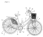
- the bicycle in which an embodiment of the present invention is used is a recreational bicycle comprising a frame 1 with a double loop type of frame unit 2 and a front fork 3; a handlebar assembly 4; a saddle 11, a drive component 5; a front wheel 6; a rear wheel 7 in which a four-speed internal electrical shifter hub 10 is mounted; front and rear brake devices 8 (only front one shown in figure); and a shift control element 9 for conveniently operating the internal electrical shifter hub 10.
- a bicycle speed sensor 12 is provided to a chain stay 2a of the frame unit 2. This bicycle speed sensor 12 outputs a bicycle speed signal by detecting a magnet 13 mounted on a spoke 7a of the rear wheel 7.
- the handlebar assembly 4 has a handle stem 14 that is fixed to the upper portion of the front fork 3 and a handlebar 15 that is fixed to the handle stem 14.
- Brake levers 16 and grips 17. which constitute part of the brake devices 8. are mounted at either end of the handlebar 15.
- the control panel 20 of the shift control element 9 is formed integrally with the right-side brake lever 16.
- the shift control element 9 is connected to a shift control component 25 through a control cable 9a.
- the shift control component 25 is mounted on the base of the chain stay 2a.
- the drive component 5 comprises a bottom bracket axle assembly 30 mounted on the bottom bracket 2b of the frame unit 2; left- and right-side cranks 31 and 32 nonrotatably mounted on either end of the bottom bracket axle assembly 30; a chainwheel 33 that integrally rotates with the right-side crank 32; and a chain 34 wrapped around the chainwheel 33 for driving an internal shifter hub 10.
- the bottom bracket axle assembly 30 comprises left- and right-side cylindrical members 40 and 41 mounted in an inner peripheral section on the mounting side of the left- and right-side cranks 31 and 32 of the bottom bracket 2b, an axle supporting member in the form of a cylindrical bearing housing 42 whose two ends are supported by these cylindrical members 40 and 41, a hollow bottom bracket axle 43 rotatably supported by the bearing housing 42, a pair of left- and right-side rolling element groups 44a and 44b disposed between the bottom bracket axle 43 and the bearing housing 42, and four pressure sensors 45a-45d mounted between the bearing housing 42 and the left- and right-side cylindrical members 40 and 41.
- a left-side male threaded portion 40a in threaded engagement with the left-side female threaded portion 2c formed on the inner peripheral surface at the left end of the bottom bracket 2b is formed on the outer peripheral surface at the left end (Fig. 3) of the left-side cylindrical member 40.
- the size of the left-side male threaded portion 40a may, for example, be "BC 1.37 peak 24" (as defined in JIS D 9401 for bicycles) to allow mounting in the bottom bracket of a common bicycle.
- Splines 40b for securing a screw-in tool are formed in the inner peripheral section at the left end of the left-side cylindrical member 40.
- a contact portion 40c that is narrower than other portions is formed on the inner peripheral surface, and the left end of the bearing housing 42 rests against the inner end face of the contact portion 40c.
- the left-side cylindrical member 40 is locked, positioned in the direction of rotation, and fixed in the bottom bracket 2b by a locknut 50.
- Grooves 50a for securing a screw-in tool are formed in outer peripheral surface of the locknut 50 at regular intervals in the circumferential direction.
- the right-side cylindrical member 41 is a flanged cylindrical member having a flange 41a.
- the outer peripheral surface at the right end thereof is provided with a right-side male threaded portion 41b in threaded engagement with the right-side female threaded portion 2d formed on the inner peripheral surface at the right end of the bottom bracket 2b.
- the size of the right-side male threaded portion 41b may, for example, be "BC 1.37 peak 24 left" (as defined in JIS D 9401 for bicycles) for a threaded portion having the opposite direction from the direction of the left-side male threaded portion 40a to allow mounting in the bottom bracket of a common bicycle.
- Grooves 41c for securing a screw-in tool are formed in the inner peripheral surface of the flange 41a.
- a contact portion 41d that is narrower than other portions is formed on the inner peripheral surface, and knurled radial positioning grooves 41e (Fig. 6) for positioning components in the direction of rotation relative to the bearing housing 42 are formed on the end face inside the contact portion 41d. The right end of the bearing housing 42 is pressed against the positioning grooves 41e.
- the bearing housing 42 is disposed around the inside of the two cylindrical members 40 and 41, and the two ends thereof rest against the two cylindrical members 40 and 41.
- the end face on the right side of the bearing housing 42 (Fig. 3) is provided with knurled positioning grooves (not shown) in engagement with the positioning grooves 41e.
- the outer peripheral surface of the bearing housing 42 is provided with four substantially rectangular sensor-mounting depressions 46a-46d.
- the sensor-mounting depressions 46a-46d are designed for mounting pressure sensors 45a-45d between the bearing housing 42 and the respective left- and right-side cylindrical members 40 and 41.
- the sensor-mounting depression 46a is mounted in a first position on the outer peripheral surface on the mounting side of the right-side crank 32, and the sensor-mounting depression 46b is mounted in a second position opposite the first position in relation to the central position C of the bottom bracket axle 43 in the axial direction.
- the first and second positions are positions substantially on the outer peripheral side that correspond to the mounting positions of the rolling element groups 44b and 44a.
- the sensor-mounting depression 46c is formed in a third position which faces the first position in the radial direction
- the sensor-mounting depression 46d is formed in a fourth position which faces the second position in the radial direction.
- the area between the mounting depressions in the bearing housing 42 is made narrower than other portions, and a groove 47 for accommodating wires is formed over some of the area.
- Annular race surfaces 42a and 42b are formed at a distance from each other in the axial direction on the inner peripheral surface of the bearing housing 42.
- the race surfaces 42a and 42b are formed at positions symmetrical about the central position C of the bottom bracket axle 43.
- a connecting link 51 is interposed between the outer peripheral surface of the bearing housing 42 and the inner peripheral surface of the left-side cylindrical member 40.
- the connecting link 51 is a spring member obtained by bending a wire into an annular shape and designed to link the bearing housing 42 and the left-side cylindrical member 40 in a rotatably and axially immovable fashion.
- the bottom bracket axle 43 is rotatably supported in the bottom bracket 2b by means of the bearing housing 42.
- Serrations 43a and 43b for nonrotatably linking the left- and right-side cranks 31 and 32 are formed at both ends of the bottom bracket axle 43.
- annular race surfaces 43c and 43d are formed on the outer peripheral surface of the bottom bracket axle 43 at positions facing the race surfaces 42a and 42b.
- a plurality of steel balls 44c and 44d constituting the rolling element groups 44a and 44b are disposed at regular intervals in the circumferential direction between the race surfaces 42a and 42b and the race surfaces 43c and 43d in contact with these surfaces.
- the plurality of steel balls 44c and 44d disposed at regular intervals are held by retainers 44e and 44f.
- the steel balls 44c and 44d are press-fitted between the two in a manner similar to that adopted for regular ball bearings.
- Seal members 60a and 60b are placed on the outside of the rolling element groups 44a and 44b.
- the pressure sensors 45a-45d are plate-shaped members comprising wide portions 55a-55d and narrow portions 56a-56d and having fan-shaped cross sections configured such that they constitute part of a cylinder.
- the pressure sensors 45a-45d are ceramic elements that change their resistance depending on the pressure, and they are press-fitted between the bearing housing 42 and the cylindrical members 40 and 41.
- the pressure sensor 45a is disposed on the opposite side from the direction of advance of the bicycle, that is, in the rear section of the bearing housing 42, and the pressure sensor 45c is disposed in the front section of the bearing housing 42.
- the pressure sensor 45d is disposed in the rear section of the bearing housing 42
- the pressure sensor 45b is disposed in the front section of the bearing housing 42.
- Arranging the pressure sensors 45a and 45b at such positions causes the pressure applied to the pressure sensors 45a and 45b to vary markedly with torque and allows the torque acting on the bottom bracket axle 43 to be sensed with high accuracy when the chainwheel 33 is rotated by the cranks 31 and 32 and tension is created in the chain 34. That is because the tension in the chain tends to urge the bottom bracket axle 43 backward.
- providing the two sensors 45c and 45d in the respective positions facing the two pressure sensors 45a and 45b in the radial direction allows output from the pressure sensors 45a and 45b to be corrected, and the torque acting on the bottom bracket axle 43 to be sensed with higher accuracy.
- Attachment rings 53 and 52 are mounted on the narrow portions 56a and 56c and the narrow portions 56b and 56d of the pressure sensors 45a and 45c and the pressure sensors 45b and 45d, respectively.
- the attachment rings 53 and 52 which are spring members consisting of wires bent into ring shapes, are designed to prevent the pressure sensors 45a-45d from moving or falling off during mounting.
- bottom bracket axle assembly 30 thus configured is mounted on a bottom bracket 2b.
- the bottom bracket axle 43 is incorporated in advance into the bearing housing 42 with the rolling element groups 44a and 44b.
- the bearing housing 42 is incorporated into the left-side cylindrical member 40, and the two components are linked in advance by a connecting link 51.
- the right-side cylindrical member 41 is first screwed into the right-side female threaded portion 2d of the bottom bracket 2b with the aid of a screw-in tool. In the process, the right-side cylindrical member 41 is rotated counterclockwise because the right-side female threaded portion 2d is a left-handed thread. The left-side cylindrical member 40 is then screwed with the aid of a screw-in tool into the left-side female threaded portion 2c of the bottom bracket 2b. The left-side cylindrical member 40 is rotated clockwise because the left-side female threaded portion 2c is a right-handed thread.
- the rotational position of the bearing housing 42 is adjusted such that the pressure sensors 45a-45d are aligned in a prescribed direction, and the left-side cylindrical member 40 is locked in the adjusted position by a locknut 50 following adjustment.
- the positioning grooves of the bearing housing 42 and the positioning grooves 41e of the right-side cylindrical member 41 mesh with each other, thus making it difficult for the pressure sensors 45a-45d to change their rotational positions once they are adjusted.
- cranks 31 and 32 mounted on the two ends of the bottom bracket axle 43 and extending a chain 34 between the chainwheel 33 and the internal shifter hub 10 allow the rotation of the cranks 31 and 32 to be transmitted to the rear wheel 7 through the agency of the internal shifter hub 10.
- the torque sensor can be made smaller because a pressure-based torque is sensed, and the pressure sensors 45a-45d can be disposed between the bearing housing 42 and the two cylindrical members 40 and 41.
- pressure can be sensed with high efficiency because the pressure sensors are disposed near the position of maximum applied force. This position does not require high accuracy, thus making the components easier to install.
- Figure 7 is a partial cross sectional view of a particular embodiment of a bottom bracket assembly that incorporates another embodiment of a torque sensor according to the present invention.
- a left-side cylindrical member 40 in the form of a flanged cylindrical member and to position the right-side cylindrical member 41 with the aid of a locknut 50.
- the bearing housing 42 is linked to the right-side cylindrical member 41 via a connecting link 51.
- the right-side cylindrical member 41 and the bearing housing 42 are positioned in the direction of rotation with the aid of serrations 70.
- the bearing housing 42 is merely supported without coming into contact with the left-side cylindrical member 40.
- Other elements of the structure are the same as in the above-described embodiment, and their description will therefore be omitted.
- this bottom bracket axle assembly 30a To assemble this bottom bracket axle assembly 30a, the left-side cylindrical member 40 is first screwed into the bottom bracket 2b. The right-side cylindrical member 41 linked to the bearing housing 42, which is positioned in the direction of rotation, is then screwed into the bottom bracket 2b. The rotational position of the right-side cylindrical member 41 is adjusted such that the pressure sensors 45a-45d occupy the desired rotational positions, and the right-side cylindrical member 41 is locked and fixed in the bottom bracket 2b with the aid of the locknut 50.
- the bottom bracket axle assembly 30a thus configured has the same effects as the above-described embodiment.
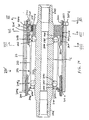
- a bottom bracket axle assembly 130 comprises left- and right-side cylindrical members 140 and 141 mounted in an inner peripheral section on the mounting side of the left- and right-side cranks of the bottom bracket 2b, a cylindrical bearing housing 142 whose two ends are supported by these cylindrical members 140 and 141, a hollow bottom bracket axle 143 rotatably supported by the bearing housing 142, a pair of left- and right-side rolling element groups 144a and 144b disposed between the bottom bracket axle 143 and the bearing housing 142, and two pressure sensors 145a and 145b mounted between the bearing housing 142 and the left- and right-side cylindrical members 140 and 141.
- a left-side male threaded portion 140a in threaded engagement with the left-side female threaded portion 2c formed on the inner peripheral surface at the left end of the bottom bracket 2b is formed on the outer peripheral surface at the left end (Fig. 8) of the left-side cylindrical member 140.
- the size of the left-side male threaded portion 140a may, for example, be "BC 1.37 peak 24" (as defined in JIS D 9401 for bicycles) to allow mounting in the bottom bracket of a common bicycle.
- Splines 140b for securing a screw-in tool are formed on the inner peripheral surface at the left end of the left-side cylindrical member 140.
- a tapered surface 140c that has a progressively smaller diameter toward the outside in the axial direction is formed on the inner peripheral surface of the inner portion, and a sensor-pressing member 160 (described below) is pushed against this tapered surface 140c.
- a discoid left-side wall 140d is formed between the tapered surface 140c and the splines 140b of the left-side cylindrical member 140.
- the bottom bracket axle 143 passes through the center of the left-side wall 140d.
- the left-side cylindrical member 140 is locked, positioned in the direction of rotation, and fixed in the bottom bracket 2b by a locknut 150.
- Grooves 150a for securing a screw-in tool are formed in outer peripheral surface of the locknut 150 at regular intervals in the circumferential direction.
- the right-side cylindrical member 141 is a cylindrical member having substantially the same shape as the left-side cylindrical member 140.
- the outer peripheral surface at the right end thereof is provided with a right-side male threaded portion 141a in threaded engagement with the right-side female threaded portion 2d formed on the inner peripheral surface at the right end of the bottom bracket 2b.
- the size of the right-side male threaded portion 141a may, for example, be "BC 1.37 peak 24 left" (as defined in JIS D 9401 for bicycles) for a threaded portion having the opposite direction from the direction of the left-side male threaded portion 140a to allow mounting in the bottom bracket of a common bicycle.
- Splines 141b for securing a screw-in tool are formed in the inner peripheral surface of outer portion.
- a tapered surface 141c that has a progressively smaller diameter toward the outside in the axial direction is formed on the inner peripheral surface of the inner portion, and a sensor-pressing member 161 (described below) is pushed against this tapered surface 141c.
- a discoid right-side wall 141d is formed between the tapered surface 141c and the splines 141b of the right-side cylindrical member 141.
- Four rectangular notches 141e (Figs. 9 and 10) for nonrotatably stopping the bearing housing 142 are formed in the center of the right-side wall 141d.
- the right-side cylindrical member 141 is locked, positioned in the direction of rotation, and fixed in the bottom bracket 2b by a locknut 151.
- Grooves 151a for securing a screw-in tool are formed in outer peripheral surface of the locknut 151 at regular intervals in the circumferential direction.
- the bearing housing 142 is disposed around the inside of the two cylindrical members 140 and 141, and the two ends thereof are brought into contact with the two cylindrical members 140 and 141 through the sensor-pressing members 160 and 161.
- the bearing housing 142 comprises a cylindrical housing body 162 in which two rolling element groups 144a and 144b are disposed around the inside at a distance from each other in the axial direction.
- a pair of sensor-mounting members 163a and 163b are mounted on the two ends of the housing body 162.
- Annular race surfaces 142a and 142b are formed at a distance from each other in the axial direction on the inner peripheral surface of the housing body 162.
- the race surfaces 142a and 142b are formed at positions that are symmetrical about the central position C of the bottom bracket axle 43.
- the sensor-pressing members 160 and 161 are disposed between the sensor-mounting members 163a and 163b and the tapered surfaces 140c and 141c of the left- and right-side cylindrical members 140 and 141 while allowed to come into close contact with the pressure sensors 145b and 145a.
- the sensor-pressing members 160 and 161 are designed to bring the pressure sensors 145b and 145a into close contact with the first and second sensor mounting members 163a and 163b and to firmly secure the pressure sensors 145a and 145b against first and second sensor mounting members 163a and 163b without creating any chatter.
- the sensor-pressing members 160 and 161 are elastic metal members that have a substantially cylindrical shape and that are provided along the outer peripheral surfaces thereof with tapered surfaces 160a and 161a. The tapered surfaces have a progressively smaller diameter toward the outside in the axial direction.
- the cross sections of the inner peripheral surfaces of the sensor-pressing members 160 and 161 are substantially perfect octagons, and the pressure sensors 145a and 145b and the sensor-mounting members 163a and 163b are pressed against the inner peripheral surfaces of these perfect octagons.
- the sensor-pressing members 160 and 161 are provided with a plurality of slits 160b and 161b that are cut such that they pass through the inner and outer peripheries in the axial direction.
- the slits 160b and 161b are formed in the sensor-mounting sections.
- the slits 160b and 161b form a structure in which grooves extending from either end of the sensor-pressing members 160 and 161 toward the end portion on the other side are arranged in four groups at regular intervals in the radial direction. Providing such slits makes it easier for the sensor-pressing members 160 and 161 to contact and expand in the radial direction, and they ensure that the pressure sensors 145b and 145a can be brought into close contact.
- the sensor-mounting members 163a and 163b comprise wide cylindrical components 165a and 165b tightly fitted over the outer peripheral surfaces at the two ends of the housing body 162, and mounting components 166a and 166b that are integrally formed on the two ends of the cylindrical components 165a and 165b and that have outer peripheral surfaces in the form of irregular octagons. Grooved sections 170a and 170b for wires are formed adjacent to the mounting sections of the pressure sensors 145b and 145a of the cylindrical components 165a and 165b.
- the mounting components 166a and 166b which are disposed facing the inner peripheral sides of the sensor-pressing members 160 and 161, have mounting surfaces 164a and 164b on their respective outer peripheral surfaces.
- the pressure sensor 145b and pressure sensor 145a can be mounted on these mounting surfaces. As shown in Figs.
- the mounting components 166a and 166b in which the outer peripheral surfaces facing the sensor-pressing members 160 and 161 have irregular octagonal shapes in cross section, are spaced apart from the inner peripheral surfaces of the sensor-pressing members 160 and 161 along the mounting surfaces 164a and 164b, along the two surfaces 167a and 167b adjacent to the mounting surfaces 164a and 164b, and along the two facing surfaces 168a and 168b located opposite the two surfaces 167a and 167b, and are brought into contact with the inner peripheral surfaces of the sensor-pressing members 160 and 161 along a pair of contact surfaces 169a and 169b facing each other between the two surfaces 167a and 167b and the facing surfaces 168a and 168b.
- the tip of the right-side mounting component 166b is provided with four engagement protrusions 166c for engaging the four rectangular notches 141e formed in the center of the right-side wall 141d of the right-side cylindrical member 141, with the protrusions extending in the axial direction.
- the pressure sensor 145a can be positioned in the rear section of the bearing housing 142 by causing the engagement protrusions 166c to engage the notches 141e, as described below.
- the bottom bracket axle 143 is rotatably supported in the bottom bracket 2b by means of the bearing housing 142.
- Chamfered portions 143a and 143b for the nonrotatable linkage of right and left cranks are formed at the two ends of the bottom bracket axle 143.
- annular race surfaces 143c and 143d are formed on the outer peripheral surface of the bottom bracket axle 143 at positions facing the race surfaces 142a and 142b.
- a plurality of steel balls 144c and 144d constituting the rolling element groups 144a and 144b are disposed at regular intervals in the circumferential direction between the race surfaces 142a and 142b and the race surfaces 143c and 143d in contact with these surfaces.
- the plurality of steel balls 144c and 144d disposed at regular intervals are held by retainers 144e and 144f.
- the steel balls 144c and 144d are press-fitted between the two component in a manner similar to that adopted for regular ball bearings.
- the sensor-mounting members 163a and 163b are mounted in combination with seal members outside the rolling element groups 144a and 144b.
- the pressure sensors 145a and 145b which are members shaped as rectangular plates in the manner shown in Fig. 9, are ceramic elements whose resistance varies with pressure.
- the pressure sensors 145b and 145a are press-fitted between the left- and right-side cylindrical members 140 and 141 and the left- and right-side sensor-mounting members 163a and 163b of the bearing housing 142.
- the pressure sensor 145a is disposed on the side opposite the direction of travel of the bicycle, that is, in the rear section of the bearing housing 142 (as shown in Fig. 10), and the pressure sensor 145b is disposed in the front section of the bearing housing 142, as shown in Fig. 11.
- Arranging the pressure sensors 145a and 145b at such positions causes the pressure applied to the pressure sensors 145a and 145b to vary markedly with torque and allows the torque acting on the bottom bracket axle 143 to be sensed with high accuracy when the chainwheel 33 is rotated by the cranks 31 and 32 and tension is created in the chain 34.
- the tension in chain 34 tends to urge the bottom bracket axle 143 backward.
- bottom bracket axle assembly 130 thus configured is mounted on a bottom bracket 2b.
- the bottom bracket axle 143 is incorporated in advance into the bearing housing 142 with the rolling element groups 144a and 144b.
- the sensor-pressing members 160 and 161 and the pressure sensors 145b and 145a are mounted on both ends of the bearing housing 142.
- the left- and right-side pressure sensors 145b and 145a are disposed diagonally opposite to each other.
- the right-side cylindrical member 141 is screwed with the aid of a screw-in tool into the right-side female threaded portion 2d of the bottom bracket 2b until one of the notches 141e of the right-side cylindrical member 141 reaches an appropriate position that faces the forward section.
- the right-side cylindrical member 141 is rotated counterclockwise because the right-side female threaded portion 2d is a left-handed thread.
- the bearing housing 142 which is provided with the sensor-pressing members 160 and 161 mounted on the two ends thereof, is subsequently inserted into the bottom bracket 2b until a position is reached in which the engagement protrusions 166c engage the notches 141e such that the pressure sensor 145a is disposed in the rear section.
- the left-side cylindrical member 140 is then screwed with the aid of a screw-in tool into the left-side female threaded portion 2c of the bottom bracket 2b.
- the left-side cylindrical member 140 is rotated clockwise because the left-side female threaded portion 2c is a right-handed thread.
- Fastening the left-side cylindrical member 140 with a prescribed torque allows the sensor-pressing members 160 and 161 to be compressed by the wedge action of the double-tapered surfaces 140c, 160a, 141c, and 161a, and firmly attaches the pressure sensors 145b and 145a to the mounting surfaces 164a and 164b.
- the chatter of the pressure sensors 145b and 145a can therefore be reduced, and the sensors can be securely fixed in the bearing housing 142.
- the left- and right-side cylindrical members 140 and 141 are locked in the adjusted positions with locknuts 150 and 151.
- cranks 31 and 32 mounted on the two ends of the bottom bracket axle 143 and extending a chain 34 between the chainwheel 33 and the internal shifter hub 10 allow the rotation of the cranks 31 and 32 to be transmitted to the rear wheel 7 through the internal shifter hub 10.
- two pressure sensors 145b and 145a are mounted outside a housing body 162 provided with rolling element groups 144a and 144b, thus making it possible to place the two pressure sensors 145b and 145a close to the center in the radial direction.
- the two pressure sensors 145b and 145a can therefore be mounted without any reduction in the radial dimensions.
- the pressure sensors 145b and 145a are attached to the mounting surfaces 164a and 164b by the sensor-pressing members 160 and 161, thus making it possible to fix the pressure sensors 145b and 145a securely and without any chatter. Force can therefore be transmitted to the pressure sensors 145b and 145a with high efficiency, and the sensitivity of the pressure sensors 145b and 145a can be improved.
- FIG 12 is a cross sectional view of a particular embodiment of a bottom bracket assembly 230 that incorporates another embodiment of a torque sensor according to the present invention
- Figure 13 is a view taken along line XIII-XIII in Figure 12.
- a bottom bracket axle assembly 230 comprises left- and right-side cylindrical members 240 and 241 mounted on the ends of the bottom bracket 2b, a cylindrical bearing housing 242, a hollow bottom bracket axle 243 rotatably supported by the bearing housing 242 through a pair of left- and right-side rolling element groups 244a and 244b, a sensor mounting member 263 mounted on the right side of bearing housing 242, a pressure sensor 245 mounted on an outer peripheral surface of sensor mounting member 263, and a sensor pressing member 260 disposed between pressure sensor 245 and right-side cylindrical member 241.
- Bearing housing 242 comprises a cylindrical housing body 262.
- Annular race surfaces 242a and 242b are formed at a distance from each other in the axial direction on the inner peripheral surface of the housing body 262.
- the race surfaces 242a and 242b are formed at positions that are symmetrical about the central position C of the bottom bracket axle 243.
- Bottom bracket axle 243 is a generally hollow member having chamfered portions 243a and 243b at opposite ends thereof for the nonrotatable linkage of right and left cranks
- annular race surfaces 243c and 243d are formed on the outer peripheral surface of the bottom bracket axle 243 at positions facing the race surfaces 242a and 242b of bearing housing 242.
- a plurality of steel balls 244c and 244d constituting the rolling element groups 244a and 244b are disposed at regular intervals in the circumferential direction between the race surfaces 242a and 242b and the race surfaces 243c and 243d in contact with these surfaces.
- the plurality of steel balls 244c and 244d are held at these regular intervals by retainers 244e and 144f.
- the steel balls 244c and 244d are press-fitted between the two component in a manner similar to that adopted for regular ball bearings.
- a threaded outer peripheral surface 240a of left-side cylindrical member 240 threadingly engages a threaded inner peripheral surface 2c at the left end of the bottom bracket 2b.
- the size of threaded outer peripheral surface 240a may, for example, be "BC 1.37 peak 24" (as defined in JIS D 9401 for bicycles) to allow mounting in the bottom bracket of a common bicycle.
- a concave inner peripheral surface 240c of left-side cylindrical member 240 abuts against a convex end 242x of bearing housing 242 to position bearing housing 242 in bottom bracket 2b.
- Splines 240b for engaging a screw-in tool are formed at the left-side inner peripheral surface of the left-side cylindrical member 240.
- a discoid left-side wall 240d is formed between the concave surface 240c and the splines 240b, and an annular seal member 290 is fitted between axle 243 and left-side wall 240d.
- Bottom bracket axle 243 passes through the center of the left-side wall 240d.
- the right-side cylindrical member 241 is shaped somewhat differently from the left-side cylindrical member 240.
- a threaded outer peripheral surface 241a of right-side cylindrical member 241 threadingly engages a threaded inner peripheral surface 2d at the right end of the bottom bracket 2b.
- the size of the threaded outer peripheral surface 241a may, for example, be "BC 1.37 peak 24 left" (as defined in JIS D 9401 for bicycles) which is threaded in the opposite direction from the threaded outer peripheral surface 240a of left-side cylindrical member 240 to allow mounting in the bottom bracket of a common bicycle.
- Splines 241b for engaging a screw-in tool are formed in the inner peripheral surface of cylindrical member 241.
- a surface 241c that is flat in the axial and circumferential directions is formed on the inner peripheral surface of right-side cylindrical member 241, and sensor-pressing member 260 (described below) is pushed against this flat surface 241c.
- Three surfaces 241e, 241f and 241g (Fig. 13) that are flat in the axial and circumferential directions are formed on the inner peripheral surface of cylindrical member 241 for nonrotatably engaging a sensor mounting member 263 (described below), wherein surface 241e is located diametrically opposite surface 241c, surface 241f is diametrically opposite surface 241g, and surfaces 241f and 241g are orthogonal to surfaces 241c and 241e.
- the right-side cylindrical member 241 is locked, positioned in the direction of rotation, and fixed in the bottom bracket 2b by a locknut 251.
- Grooves 251a for engaging a screw-in tool are formed in the outer peripheral surface of the locknut 251 at regular intervals in the circumferential direction.
- a sensor-mounting member 263 is mounted on the right side end of the housing body 262.
- Sensor-mounting member 263 comprises a larger diameter cylindrical component 265 tightly fitted over the outer peripheral surface of the housing body 262, and a smaller diameter sensor mounting component 266 that extends from the right side of larger diameter cylindrical component 265.
- a concave inner peripheral surface 263a of sensor mounting member 263 abuts against a convex end 242y of bearing housing 242 to position bearing housing 242 in bottom bracket 2b.
- a surface 266a that is flat in the axial and circumferential directions is formed on the outer peripheral surface of smaller diameter sensor mounting component 266, and pressure sensor 245 is pushed against this flat surface 266a.
- Three surfaces 266b, 266c and 266d (Fig.
- pressure sensor 245 is shaped as a rectangular plate and is a ceramic element whose resistance varies with pressure.
- sensor pressing member 260 is a generally rectangular, square or round plate-shaped member having a flat bottom surface 260a contacting pressure sensor 245 and a curved, preferably rounded and preferably spherical upper surface 260b having a substantially constant radius of curvature contacting flat surface 241c of right-side cylindrical member 241.
- the flat bottom surface 260a helps ensure that the pressure applied between pressure sensor 245 and sensor pressing member 260 is evenly distributed along the upper surface of pressure sensor 245, thus avoiding localized points of high pressure against the generally fragile ceramic pressure sensor 245 and providing more accurate pressure measurements.
- the generally spherical upper surface 260b of sensor pressing member 260 contacts the flat surface 241c at a point, thus allowing the sensor pressing member 260 to spread out and distribute the contact force evenly along the flat bottom surface 260a, again preventing localized points of high pressure against the generally fragile ceramic pressure sensor 245 and providing more accurate pressure measurements.
- the pressure sensor 245 preferably is disposed on the side opposite the direction of travel of the bicycle, that is, in the rear section of the bearing housing 242. Although only one pressure sensor 245 is shown located on the right-side of bottom bracket axle assembly 230, a second pressure sensor and accompanying components similar to that shown for the right-side of bottom bracket assembly 230 may be provided on the left-side of bottom-bracket axle assembly 230 and mounted on the front side of bottom bracket axle assembly 230 similar to the above embodiments.
- FIG 14 is a cross sectional view of a particular embodiment of a bottom bracket assembly 230' that incorporates another embodiment of a torque sensor according to the present invention
- Figure 15 is a view taken along line XV-XV in Figure 14
- Figure 16 is a view taken along line XVI-XVI in Figure 14
- Figure 17 is a view taken along line XVII-XVII in Figure 14.
- This embodiment is similar to the embodiment shown in Figures 12 and 13, so identical components are numbered the same.
- Bottom bracket axle assembly 230' differs from bottom bracket axle assembly 230 shown in Figures 12 and 13 in that right-side tubular member 241 and sensor mounting member 263 are formed into a one-piece sensor mounting tubular member 360.
- sensor mounting tubular member 360 has a threaded outer peripheral surface 360a that engages threaded inner peripheral surface 2d of bottom bracket 2b, a concave inner peripheral surface 360b that abuts against convex end 242y of bearing housing 242 to position bearing housing 242 in bottom bracket 2b, and a plurality of splines 360c for engaging a screw-in tool at the right-side inner peripheral surface.
- An arcuate sensor retaining portion 360d (Fig. 16) is spaced apart from a central portion 360e for forming an arcuate space 360f.
- Central portion 360e has a surface 360g that is flat in the axial and circumferential directions, and pressure sensor 245 is placed on this flat surface 360g.
- Sensor retaining portion 360d has a concave cavity 360h with a surface 360i that is flat in the axial and radial directions for contacting the upper surface 260b of sensor pressing member 260.
- the operation and advantages are the same as with the embodiment shown in Figures 12 and 13 except that this embodiment also is simpler to assemble because of the one-piece sensor mounting tubular member 360.
- the pressure sensor 245 preferably is disposed on the side opposite the direction of travel of the bicycle, that is, in the rear section of the bearing housing 242.
- a second pressure sensor and accompanying components similar to that shown for the right-side of bottom bracket assembly 230' may be provided on the left-side of bottom-bracket axle assembly 230' and mounted on the front side of bottom bracket axle assembly 230' similar to the embodiments shown in Figures 3. 7 and 8.
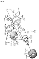
- Figure 18 is a cross sectional view of a particular embodiment of a bottom bracket assembly 230'' that incorporates another embodiment of a torque sensor according to the present invention
- Figure 19 is a view taken along line XIX-XIX in Figure 18.
- Figure 20 is an exploded view of the bottom bracket assembly 230" of Figure 18. This embodiment is similar to the embodiment shown in Figures 12 and 13, so identical components are numbered the same.
- Bottom bracket axle assembly 230" differs from bottom bracket axle assembly 230 shown in Figures 12 and 13 in that flat surfaces 241f and 241g of right-side cylindrical member 241 in that embodiment have been replaced by curved surfaces 241p and 241q with corresponding bearing recesses 241r and 241s, and rollers in the form of ball bearings 295 and 296 have been placed in bearing recesses 241r and 241s, respectively.
- Bearings 295 and 296 provide radial support between small diameter sensor mounting portion 266 and right-side cylindrical member 241, but they eliminate the friction inherent in the contacting surfaces 241f, 241g, 266c and 266d shown in Figure 13. This, in turn, provides a more accurate measure of pressure from pressure sensor 245.
- the pressure sensor 245 preferably is disposed on the side opposite the direction of travel of the bicycle, that is, in the rear section of the bearing housing 242.
- a second pressure sensor and accompanying components similar to that shown for the right-side of bottom bracket assembly 230" may be provided on the left-side of bottom-bracket axle assembly 230" and mounted on the front side of bottom bracket axle assembly 230" similar to the embodiments shown in Figures 3, 7 and 8.
- shift timing was controlled based on the torque sensed using the output of a pressure sensor.
- a pressure sensor In the case of a power-assisted bike, however, it is also possible to control motor output for propulsion on the basis of torque.
- pressure sensors were provided at four positions to improve torque sensing accuracy in the first and second embodiments, but a single pressure sensor may also be used. The mounting position thereof is not limited by the above-described embodiments.
Abstract
Description
- The present invention is directed to bicycles and, more particularly, to a torque sensor for a bicycle bottom bracket assembly.
- In power-assisted bikes, which are bicycles in which an electric motor is used as auxiliary motive power, the auxiliary motive power is delivered in accordance with drive torque. Consequently, such power-assisted bikes are provided with torque sensors for sensing the drive torque. These sensors are installed, for example, in the bottom bracket axle assembly (which supports the pedals and crank arms) as shown in Japanese Unexamined Patent Applications (Kokai) 8-297059 and 8-313375. Such torque sensors are used not only for controlling the motor output of power-assisted bikes but also for controlling the shift timing of automatic shifting devices, for example.
- The torque sensor disclosed in the first document comprises a drive shell fixedly fitted over the bottom bracket axle and provided with a chainwheel at one end, a magnetic material applied to the drive shell, and a coil unit mounted around the outside of the magnetic material of the bottom bracket. In such a torque sensor, the magnetic material develops a strain proportional to the torque when torsional force is generated by the rotation of the cranks. When strain is created in the magnetic material, the magnetic permeability of this material varies in accordance with the strain, thus changing the voltage of the coil unit. The torque is sensed based on the changes in this voltage.
- Since this torque sensor senses a torque that varies with the strain of the magnetic material, it requires complex electrical circuitry for sensing very small strains. Additionally, the accuracy with which the magnetic material or the coil unit is mounted must be kept at a high level in order to measure such small strains. The sensor is therefore difficult to mount. Furthermore, the need to mount a coil unit in the bottom bracket makes it impossible to mount a bottom bracket axle assembly having a torque sensor in the bottom bracket of a standardized bicycle and fails to provide interchangeability with commercially available bottom bracket axle assemblies.
- The torque sensor disclosed in the second document comprises a follower disk that rotates integrally with the chainwheel and that is rotatably mounted on the bottom bracket axle, a drive disk that rotates together with the bottom bracket axle, a spring plate for connecting the two disks, and a proximity switch facing the two disks and designed to sense the phase difference between the two disks. With such a torque sensor, the rotation of the cranks is transmitted to the chainwheel via the bottom bracket axle, drive disk, spring plate, and follower disk.
- Unfortunately, this torque sensor requires that two disks be provided around the bottom bracket axle and that a proximity switch be installed facing these disks, thus complicating the structure of the bottom bracket axle assembly and increasing its radial dimensions. This, in turn, requires a larger bottom bracket on the bicycle. Thus, a bottom bracket axle assembly having this torque sensor cannot be mounted on the bottom bracket of a standardized bicycle, and it is impossible to provide interchangeability with commercially available bottom bracket axle assemblies. There is therefore a need for a torque sensor for a bicycle bottom bracket assembly that has a compact structure, is easy to install, and which may be used with existing and commercially available bottom brackets.
- According to the present invention there is provided a torque sensor for a bicycle bottom bracket assembly in accordance with Claim 1. In one embodiment of the present invention, a torque sensor for a bicycle bottom bracket assembly having a bottom bracket axle includes an axle supporting member for supporting the axle for rotation around a support axis. The axle supporting member has a first sensor mounting location, and a first pressure sensor is provided for placement at the first sensor mounting location. In a more specific embodiment, the axle supporting member includes a second sensor mounting location and a second pressure sensor is provided for placement at the second sensor mounting location. The second sensor mounting location may be spaced apart from the first sensor mounting location in the direction of the support axis. In this case the second sensor mounting location may face the first sensor mounting location in the direction of the support axis or may be disposed diagonally across from the first sensor mounting location in the direction of the support axis. Alternatively, the second sensor mounting location may face the first sensor mounting location in the radial direction of the axle supporting member.
- In an even more specific embodiment, the axle supporting member may include a second sensor mounting location spaced apart from the first sensor mounting location in the direction of the support axis, a third sensor mounting location spaced apart from the first sensor mounting location in a radial direction of the axle supporting member, and a fourth sensor mounting location spaced apart from the third sensor mounting location in the direction of the support axis. A second pressure sensor may be provided for placement at the second sensor mounting location, a third pressure sensor may be provided for placement at the third sensor mounting location, and a fourth pressure sensor may be provided for placement at the fourth sensor mounting location. If desired, the second sensor mounting location may face the first sensor mounting location in the direction of the support axis, the fourth sensor mounting location may face the third sensor mounting location in the direction of the support axis, the third sensor mounting location may face the first sensor mounting location in the radial direction of the axle supporting member, and the fourth sensor mounting location may face the second sensor mounting location in the radial direction of the axle supporting member.
- In a more specific embodiment of the invention directed to a more complete portion of the bottom bracket assembly, a torque sensor for the bicycle bottom bracket assembly includes an axle having an axle axis, a first bearing including a plurality of first rollers disposed on the axle, and a second bearing including a plurality of second rollers disposed on the axle. The first bearing is spaced apart from the second bearing in the direction of the axle axis. A tubular bearing housing surrounds the axle so that the first bearing and the second bearing are disposed between the axle and the bearing housing and so that the axle is rotatably supported in the bearing housing. A first tubular member is disposed at a first end of the bearing housing, and a second tubular member is disposed at a second end of the bearing housing. A first pressure sensor is disposed between the first tubular member and the bearing housing.
- If desired, a second pressure sensor may be disposed between the second tubular member and the bearing housing. More specifically, the first tubular member may be disposed about an outer peripheral surface of the bearing housing, and the second tubular member may be disposed about the outer peripheral surface of the bearing housing. In such a case the first pressure sensor may be disposed between an inner peripheral surface of the first tubular member and the outer peripheral surface of the bearing housing, and the second pressure sensor may be disposed between an inner peripheral surface of the second tubular member and the outer peripheral surface of the bearing housing. The second pressure sensor may be located diagonally across from the first pressure sensor in the direction of the axle axis, or else the second pressure sensor can face the first pressure sensor in the direction of the axle axis.
- In a further embodiment of this type, a third pressure sensor may be disposed between the inner peripheral surface of the first tubular member and the outer peripheral surface of the bearing housing, and a fourth pressure sensor may be disposed between the inner peripheral surface of the second tubular member and the outer peripheral surface of the bearing housing. The third pressure sensor may face the first pressure sensor in a radial direction of the bearing housing, and the fourth pressure sensor may face the second pressure sensor in the radial direction of the bearing housing.
- In an even further embodiment of the present invention, a first sensor mounting member having a first sensor mounting location may be provided, wherein the first sensor mounting member is disposed between the bearing housing and the first tubular member. In this case the first pressure sensor is disposed at the first sensor mounting location. If the first pressure sensor is disposed radially outwardly of the first sensor mounting member, then a first sensor pressing member may be disposed between the first pressure sensor and the first tubular member. As with the above embodiments, a second sensor mounting member having a second sensor mounting location may be provided, wherein the second sensor mounting member is disposed between the bearing housing and the second tubular member. In this case the first pressure sensor may be located diagonally across from the second pressure sensor in the direction of the axle axis. If the first pressure sensor is disposed radially outwardly of the first sensor mounting member and the second pressure sensor is disposed radially outwardly of the second sensor mounting member, then a first sensor pressing member may be disposed between the first pressure sensor and the first tubular member, and a second sensor pressing member may be disposed between the second pressure sensor and the second tubular member.
- If desired, the first sensor mounting member and the second sensor mounting member each may have an outer peripheral surface in a shape of an octagon, and the first sensor pressing member and the second sensor pressing member each may have an inner peripheral surface in a shape of an octagon. A first flat side of the first sensor mounting member faces the first pressure sensor, and a second flat side of the second sensor mounting member faces the second pressure sensor. Two flanking sides of the outer peripheral surface of the first sensor mounting member adjacent to and flanking the first flat side may be spaced apart from the inner peripheral surface of the first sensor pressing member, and two diametrically opposite spaced sides of the outer peripheral surface of the first sensor mounting member diametrically opposite the two flanking sides of the first sensor mounting member may be spaced apart from the inner peripheral surface of the first sensor pressing member. Similarly, two flanking sides of the outer peripheral surface of the second sensor mounting member adjacent to and flanking the second flat side may be spaced apart from the inner peripheral surface of the second sensor pressing member, and two diametrically opposite spaced sides of the outer peripheral surface of the second sensor mounting member diametrically opposite the two flanking sides of the second mounting member may be spaced apart from the inner peripheral surface of the second sensor pressing member. Additionally, two diametrically opposite sides of the outer peripheral surface of the first sensor mounting member between the two flanking sides of the first sensor mounting member and the two diametrically opposite spaced sides of the first sensor mounting member may contact the inner peripheral surface of the first sensor pressing member, and two diametrically opposite sides of the outer peripheral surface of the second sensor mounting member between the two flanking sides of the second sensor mounting member and the two diametrically opposite spaced sides of the second sensor mounting member may contact the inner peripheral surface of the second sensor pressing member.
- In yet another embodiment, the first sensor pressing member may have a curved outer peripheral surface facing an inner peripheral surface of the first tubular member. Such a curved surface helps to distribute the pressure exerted between the first tubular member and the sensor pressing member evenly to the pressure sensor.
-
- Figure 1 is a side view of a bicycle that incorporates a particular embodiment of a torque sensor for a bottom bracket assembly according to the present invention;
- Figure 2 is a more detailed view of a portion of the bicycle frame shown in Figure 1;
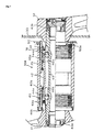
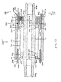
- Figure 3 is a partial cross sectional view of a particular embodiment of a bottom bracket assembly that incorporates a torque sensor according to the present invention;
- Figure 4 is an exploded view of the bottom bracket axle assembly shown in Figure 3;
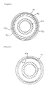
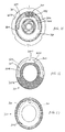
- Figure 5 is a view taken along line V-V in Figure 3;
- Figure 6 is a view taken along line VI-VI in Figure 3;
- Figure 7 is a partial cross sectional view of a particular embodiment of a bottom bracket assembly that incorporates another embodiment of a torque sensor according to the present invention;
- Figure 8 is a partial cross sectional view of a particular embodiment of a bottom bracket assembly that incorporates another embodiment of a torque sensor according to the present invention;
- Figure 9 is an exploded view of the bottom bracket axle assembly shown in Figure 8;
- Figure 10 is a view taken along line X-X in Figure 8 with the upper portion partially cut away to show the pressure sensor;
- Figure 11 is a view taken along line XI-XI in Figure 8;
- Figure 12 is a cross sectional view of a particular embodiment of a bottom bracket assembly that incorporates another embodiment of a torque sensor according to the present invention;
- Figure 13 is a view taken along line XIII-XIII in Figure 12;
- Figure 14 is a cross sectional view of a particular embodiment of a bottom bracket assembly that incorporates another embodiment of a torque sensor according to the present invention;
- Figure 15 is a view taken along line XV-XV in Figure 14;
- Figure 16 is a view taken along line XVI-XVI in Figure 14;
- Figure 17 is a view taken along line XVII-XVII in Figure 14;
- Figure 18 is a cross sectional view of a particular embodiment of a bottom bracket assembly that incorporates another embodiment of a torque sensor according to the present invention;
- Figure 19 is a view taken along line XIX-XIX in Figure 18.
- Figure 20 is an exploded view of the bottom bracket axle assembly shown in Figure 18.
-
- In Fig. 1, the bicycle in which an embodiment of the present invention is used is a recreational bicycle comprising a frame 1 with a double loop type of
frame unit 2 and afront fork 3; ahandlebar assembly 4; asaddle 11, adrive component 5; afront wheel 6; arear wheel 7 in which a four-speed internalelectrical shifter hub 10 is mounted; front and rear brake devices 8 (only front one shown in figure); and ashift control element 9 for conveniently operating the internalelectrical shifter hub 10. As is also shown in Fig. 2, abicycle speed sensor 12 is provided to achain stay 2a of theframe unit 2. Thisbicycle speed sensor 12 outputs a bicycle speed signal by detecting amagnet 13 mounted on aspoke 7a of therear wheel 7. - The
handlebar assembly 4 has ahandle stem 14 that is fixed to the upper portion of thefront fork 3 and ahandlebar 15 that is fixed to thehandle stem 14. Brake levers 16 and grips 17. which constitute part of thebrake devices 8. are mounted at either end of thehandlebar 15. Thecontrol panel 20 of theshift control element 9 is formed integrally with the right-side brake lever 16. Theshift control element 9 is connected to ashift control component 25 through acontrol cable 9a. Theshift control component 25 is mounted on the base of thechain stay 2a. - The
drive component 5 comprises a bottombracket axle assembly 30 mounted on thebottom bracket 2b of theframe unit 2; left- and right-side cranks 31 and 32 nonrotatably mounted on either end of the bottombracket axle assembly 30; achainwheel 33 that integrally rotates with the right-side crank 32; and achain 34 wrapped around thechainwheel 33 for driving aninternal shifter hub 10. - As shown in Figs. 3-6, the bottom
bracket axle assembly 30 comprises left- and right-sidecylindrical members bottom bracket 2b, an axle supporting member in the form of a cylindrical bearinghousing 42 whose two ends are supported by thesecylindrical members bottom bracket axle 43 rotatably supported by the bearinghousing 42, a pair of left- and right-siderolling element groups bottom bracket axle 43 and the bearinghousing 42, and fourpressure sensors 45a-45d mounted between the bearinghousing 42 and the left- and right-sidecylindrical members - A left-side male threaded
portion 40a in threaded engagement with the left-side female threadedportion 2c formed on the inner peripheral surface at the left end of thebottom bracket 2b is formed on the outer peripheral surface at the left end (Fig. 3) of the left-sidecylindrical member 40. The size of the left-side male threadedportion 40a may, for example, be "BC 1.37peak 24" (as defined in JIS D 9401 for bicycles) to allow mounting in the bottom bracket of a common bicycle.Splines 40b for securing a screw-in tool are formed in the inner peripheral section at the left end of the left-sidecylindrical member 40. In addition, acontact portion 40c that is narrower than other portions is formed on the inner peripheral surface, and the left end of the bearinghousing 42 rests against the inner end face of thecontact portion 40c. The left-sidecylindrical member 40 is locked, positioned in the direction of rotation, and fixed in thebottom bracket 2b by alocknut 50.Grooves 50a for securing a screw-in tool are formed in outer peripheral surface of thelocknut 50 at regular intervals in the circumferential direction. - The right-side
cylindrical member 41 is a flanged cylindrical member having aflange 41a. The outer peripheral surface at the right end thereof is provided with a right-side male threadedportion 41b in threaded engagement with the right-side female threadedportion 2d formed on the inner peripheral surface at the right end of thebottom bracket 2b. The size of the right-side male threadedportion 41b may, for example, be "BC 1.37peak 24 left" (as defined in JIS D 9401 for bicycles) for a threaded portion having the opposite direction from the direction of the left-side male threadedportion 40a to allow mounting in the bottom bracket of a common bicycle.Grooves 41c for securing a screw-in tool are formed in the inner peripheral surface of theflange 41a. In addition, acontact portion 41d that is narrower than other portions is formed on the inner peripheral surface, and knurledradial positioning grooves 41e (Fig. 6) for positioning components in the direction of rotation relative to the bearinghousing 42 are formed on the end face inside thecontact portion 41d. The right end of the bearinghousing 42 is pressed against thepositioning grooves 41e. - The bearing
housing 42 is disposed around the inside of the twocylindrical members cylindrical members positioning grooves 41e. The outer peripheral surface of the bearinghousing 42 is provided with four substantially rectangular sensor-mounting depressions 46a-46d. The sensor-mounting depressions 46a-46d are designed for mountingpressure sensors 45a-45d between the bearinghousing 42 and the respective left- and right-sidecylindrical members - The sensor-mounting depression 46a is mounted in a first position on the outer peripheral surface on the mounting side of the right-side crank 32, and the sensor-mounting
depression 46b is mounted in a second position opposite the first position in relation to the central position C of thebottom bracket axle 43 in the axial direction. The first and second positions are positions substantially on the outer peripheral side that correspond to the mounting positions of the rollingelement groups depression 46c is formed in a third position which faces the first position in the radial direction, and the sensor-mountingdepression 46d is formed in a fourth position which faces the second position in the radial direction. As a result, thepressure sensor 45a and thepressure sensor 45d are positioned at a distance from each other in the axial direction, as are thepressure sensor 45c and thepressure sensor 45b. - The area between the mounting depressions in the bearing
housing 42 is made narrower than other portions, and agroove 47 for accommodating wires is formed over some of the area. Annular race surfaces 42a and 42b are formed at a distance from each other in the axial direction on the inner peripheral surface of the bearinghousing 42. The race surfaces 42a and 42b are formed at positions symmetrical about the central position C of thebottom bracket axle 43. - A connecting
link 51 is interposed between the outer peripheral surface of the bearinghousing 42 and the inner peripheral surface of the left-sidecylindrical member 40. The connectinglink 51 is a spring member obtained by bending a wire into an annular shape and designed to link the bearinghousing 42 and the left-sidecylindrical member 40 in a rotatably and axially immovable fashion. - The
bottom bracket axle 43 is rotatably supported in thebottom bracket 2b by means of the bearinghousing 42.Serrations bottom bracket axle 43. In addition, annular race surfaces 43c and 43d are formed on the outer peripheral surface of thebottom bracket axle 43 at positions facing the race surfaces 42a and 42b. A plurality of steel balls 44c and 44d constituting the rollingelement groups retainers Seal members element groups - As shown in Fig. 4, the
pressure sensors 45a-45d are plate-shaped members comprisingwide portions 55a-55d andnarrow portions 56a-56d and having fan-shaped cross sections configured such that they constitute part of a cylinder. Thepressure sensors 45a-45d are ceramic elements that change their resistance depending on the pressure, and they are press-fitted between the bearinghousing 42 and thecylindrical members pressure sensor 45a is disposed on the opposite side from the direction of advance of the bicycle, that is, in the rear section of the bearinghousing 42, and thepressure sensor 45c is disposed in the front section of the bearinghousing 42. Similarly, thepressure sensor 45d is disposed in the rear section of the bearinghousing 42, and thepressure sensor 45b is disposed in the front section of the bearinghousing 42. - Arranging the
pressure sensors pressure sensors bottom bracket axle 43 to be sensed with high accuracy when thechainwheel 33 is rotated by thecranks chain 34. That is because the tension in the chain tends to urge thebottom bracket axle 43 backward. In addition, providing the twosensors pressure sensors pressure sensors bottom bracket axle 43 to be sensed with higher accuracy. - Attachment rings 53 and 52 are mounted on the
narrow portions narrow portions pressure sensors pressure sensors pressure sensors 45a-45d from moving or falling off during mounting. - Following is a description of a procedure in which the bottom
bracket axle assembly 30 thus configured is mounted on abottom bracket 2b. Thebottom bracket axle 43 is incorporated in advance into the bearinghousing 42 with the rollingelement groups housing 42 is incorporated into the left-sidecylindrical member 40, and the two components are linked in advance by a connectinglink 51. - The right-side
cylindrical member 41 is first screwed into the right-side female threadedportion 2d of thebottom bracket 2b with the aid of a screw-in tool. In the process, the right-sidecylindrical member 41 is rotated counterclockwise because the right-side female threadedportion 2d is a left-handed thread. The left-sidecylindrical member 40 is then screwed with the aid of a screw-in tool into the left-side female threadedportion 2c of thebottom bracket 2b. The left-sidecylindrical member 40 is rotated clockwise because the left-side female threadedportion 2c is a right-handed thread. The moment the tip of the bearinghousing 42 comes into contact with thepositioning grooves 41e of thecontact portion 41d of the right-sidecylindrical member 41, the rotational position of the bearinghousing 42 is adjusted such that thepressure sensors 45a-45d are aligned in a prescribed direction, and the left-sidecylindrical member 40 is locked in the adjusted position by alocknut 50 following adjustment. At this time, the positioning grooves of the bearinghousing 42 and thepositioning grooves 41e of the right-sidecylindrical member 41 mesh with each other, thus making it difficult for thepressure sensors 45a-45d to change their rotational positions once they are adjusted. Finally, mounting the left- and right-side cranks 31 and 32 on the two ends of thebottom bracket axle 43 and extending achain 34 between thechainwheel 33 and theinternal shifter hub 10 allow the rotation of thecranks rear wheel 7 through the agency of theinternal shifter hub 10. - When the
cranks internal shifter hub 10 through thechainwheel 33 and thechain 34, and therear wheel 7 is rotated. In the process, a torque acts on thebottom bracket axle 43 due to the generation of tension in the chain. The torque acting on thebottom bracket axle 43 creates a force that tends to urge thebottom bracket axle 43 backward. The resulting force is transmitted to the bearinghousing 42 through the rollingelement groups pressure sensors housing 42 and the twocylindrical members shift control component 25, and the shift timing is controlled in accordance with the torque and bicycle speed. - In this embodiment, the torque sensor can be made smaller because a pressure-based torque is sensed, and the
pressure sensors 45a-45d can be disposed between the bearinghousing 42 and the twocylindrical members - Figure 7 is a partial cross sectional view of a particular embodiment of a bottom bracket assembly that incorporates another embodiment of a torque sensor according to the present invention. As shown in Fig. 7, it is possible to use a left-side
cylindrical member 40 in the form of a flanged cylindrical member and to position the right-sidecylindrical member 41 with the aid of alocknut 50. In this case, the bearinghousing 42 is linked to the right-sidecylindrical member 41 via a connectinglink 51. In addition, the right-sidecylindrical member 41 and the bearinghousing 42 are positioned in the direction of rotation with the aid ofserrations 70. Furthermore, the bearinghousing 42 is merely supported without coming into contact with the left-sidecylindrical member 40. Other elements of the structure are the same as in the above-described embodiment, and their description will therefore be omitted. - To assemble this bottom
bracket axle assembly 30a, the left-sidecylindrical member 40 is first screwed into thebottom bracket 2b. The right-sidecylindrical member 41 linked to the bearinghousing 42, which is positioned in the direction of rotation, is then screwed into thebottom bracket 2b. The rotational position of the right-sidecylindrical member 41 is adjusted such that thepressure sensors 45a-45d occupy the desired rotational positions, and the right-sidecylindrical member 41 is locked and fixed in thebottom bracket 2b with the aid of thelocknut 50. The bottombracket axle assembly 30a thus configured has the same effects as the above-described embodiment. - Although the above embodiments involved an arrangement in which
pressure sensors element groups housing 42, it is also possible to place pressure sensors 145a and 145b on the outside of rolling element groups 144a and 144b, as shown in Figs. 8-11. As shown in those Figures, a bottombracket axle assembly 130 comprises left- and right-sidecylindrical members bottom bracket 2b, acylindrical bearing housing 142 whose two ends are supported by thesecylindrical members bottom bracket axle 143 rotatably supported by the bearinghousing 142, a pair of left- and right-side rolling element groups 144a and 144b disposed between thebottom bracket axle 143 and the bearinghousing 142, and two pressure sensors 145a and 145b mounted between the bearinghousing 142 and the left- and right-sidecylindrical members - A left-side male threaded portion 140a in threaded engagement with the left-side female threaded
portion 2c formed on the inner peripheral surface at the left end of thebottom bracket 2b is formed on the outer peripheral surface at the left end (Fig. 8) of the left-sidecylindrical member 140. The size of the left-side male threaded portion 140a may, for example, be "BC 1.37peak 24" (as defined in JIS D 9401 for bicycles) to allow mounting in the bottom bracket of a common bicycle. Splines 140b for securing a screw-in tool are formed on the inner peripheral surface at the left end of the left-sidecylindrical member 140. In addition, a tapered surface 140c that has a progressively smaller diameter toward the outside in the axial direction is formed on the inner peripheral surface of the inner portion, and a sensor-pressing member 160 (described below) is pushed against this tapered surface 140c. A discoid left-side wall 140d is formed between the tapered surface 140c and the splines 140b of the left-sidecylindrical member 140. Thebottom bracket axle 143 passes through the center of the left-side wall 140d. The left-sidecylindrical member 140 is locked, positioned in the direction of rotation, and fixed in thebottom bracket 2b by alocknut 150. Grooves 150a for securing a screw-in tool are formed in outer peripheral surface of thelocknut 150 at regular intervals in the circumferential direction. - The right-side
cylindrical member 141 is a cylindrical member having substantially the same shape as the left-sidecylindrical member 140. The outer peripheral surface at the right end thereof is provided with a right-side male threadedportion 141a in threaded engagement with the right-side female threadedportion 2d formed on the inner peripheral surface at the right end of thebottom bracket 2b. The size of the right-side male threadedportion 141a may, for example, be "BC 1.37peak 24 left" (as defined in JIS D 9401 for bicycles) for a threaded portion having the opposite direction from the direction of the left-side male threaded portion 140a to allow mounting in the bottom bracket of a common bicycle. Splines 141b for securing a screw-in tool are formed in the inner peripheral surface of outer portion. In addition, a tapered surface 141c that has a progressively smaller diameter toward the outside in the axial direction is formed on the inner peripheral surface of the inner portion, and a sensor-pressing member 161 (described below) is pushed against this tapered surface 141c. A discoid right-side wall 141d is formed between the tapered surface 141c and the splines 141b of the right-sidecylindrical member 141. Fourrectangular notches 141e (Figs. 9 and 10) for nonrotatably stopping the bearinghousing 142 are formed in the center of the right-side wall 141d. The right-sidecylindrical member 141 is locked, positioned in the direction of rotation, and fixed in thebottom bracket 2b by alocknut 151.Grooves 151a for securing a screw-in tool are formed in outer peripheral surface of thelocknut 151 at regular intervals in the circumferential direction. - The bearing
housing 142 is disposed around the inside of the twocylindrical members cylindrical members members housing 142 comprises acylindrical housing body 162 in which two rolling element groups 144a and 144b are disposed around the inside at a distance from each other in the axial direction. A pair of sensor-mountingmembers 163a and 163b are mounted on the two ends of thehousing body 162. Annular race surfaces 142a and 142b are formed at a distance from each other in the axial direction on the inner peripheral surface of thehousing body 162. The race surfaces 142a and 142b are formed at positions that are symmetrical about the central position C of thebottom bracket axle 43. The sensor-pressingmembers members 163a and 163b and the tapered surfaces 140c and 141c of the left- and right-sidecylindrical members - The sensor-pressing
members sensor mounting members 163a and 163b and to firmly secure the pressure sensors 145a and 145b against first and secondsensor mounting members 163a and 163b without creating any chatter. The sensor-pressingmembers surfaces 160a and 161a. The tapered surfaces have a progressively smaller diameter toward the outside in the axial direction. The cross sections of the inner peripheral surfaces of the sensor-pressingmembers members 163a and 163b are pressed against the inner peripheral surfaces of these perfect octagons. The sensor-pressingmembers members members - The sensor-mounting
members 163a and 163b comprise widecylindrical components 165a and 165b tightly fitted over the outer peripheral surfaces at the two ends of thehousing body 162, and mounting components 166a and 166b that are integrally formed on the two ends of thecylindrical components 165a and 165b and that have outer peripheral surfaces in the form of irregular octagons.Grooved sections 170a and 170b for wires are formed adjacent to the mounting sections of the pressure sensors 145b and 145a of thecylindrical components 165a and 165b. - The mounting components 166a and 166b, which are disposed facing the inner peripheral sides of the sensor-pressing
members surfaces 164a and 164b on their respective outer peripheral surfaces. The pressure sensor 145b and pressure sensor 145a can be mounted on these mounting surfaces. As shown in Figs. 10 and 11, the mounting components 166a and 166b, in which the outer peripheral surfaces facing the sensor-pressingmembers members surfaces 164a and 164b, along the two surfaces 167a and 167b adjacent to the mountingsurfaces 164a and 164b, and along the two facingsurfaces 168a and 168b located opposite the two surfaces 167a and 167b, and are brought into contact with the inner peripheral surfaces of the sensor-pressingmembers surfaces 168a and 168b. - The tip of the right-side mounting component 166b is provided with four
engagement protrusions 166c for engaging the fourrectangular notches 141e formed in the center of the right-side wall 141d of the right-sidecylindrical member 141, with the protrusions extending in the axial direction. The pressure sensor 145a can be positioned in the rear section of the bearinghousing 142 by causing theengagement protrusions 166c to engage thenotches 141e, as described below. - The
bottom bracket axle 143 is rotatably supported in thebottom bracket 2b by means of the bearinghousing 142. Chamfered portions 143a and 143b for the nonrotatable linkage of right and left cranks are formed at the two ends of thebottom bracket axle 143. In addition, annular race surfaces 143c and 143d are formed on the outer peripheral surface of thebottom bracket axle 143 at positions facing the race surfaces 142a and 142b. A plurality of steel balls 144c and 144d constituting the rolling element groups 144a and 144b are disposed at regular intervals in the circumferential direction between the race surfaces 142a and 142b and the race surfaces 143c and 143d in contact with these surfaces. The plurality of steel balls 144c and 144d disposed at regular intervals are held by retainers 144e and 144f. The steel balls 144c and 144d are press-fitted between the two component in a manner similar to that adopted for regular ball bearings. The sensor-mountingmembers 163a and 163b are mounted in combination with seal members outside the rolling element groups 144a and 144b. - The pressure sensors 145a and 145b, which are members shaped as rectangular plates in the manner shown in Fig. 9, are ceramic elements whose resistance varies with pressure. The pressure sensors 145b and 145a are press-fitted between the left- and right-side
cylindrical members members 163a and 163b of the bearinghousing 142. In this case, the pressure sensor 145a is disposed on the side opposite the direction of travel of the bicycle, that is, in the rear section of the bearing housing 142 (as shown in Fig. 10), and the pressure sensor 145b is disposed in the front section of the bearinghousing 142, as shown in Fig. 11. Arranging the pressure sensors 145a and 145b at such positions causes the pressure applied to the pressure sensors 145a and 145b to vary markedly with torque and allows the torque acting on thebottom bracket axle 143 to be sensed with high accuracy when thechainwheel 33 is rotated by thecranks chain 34. The tension inchain 34 tends to urge thebottom bracket axle 143 backward. - Following is a description of a procedure in which the bottom
bracket axle assembly 130 thus configured is mounted on abottom bracket 2b. Thebottom bracket axle 143 is incorporated in advance into the bearinghousing 142 with the rolling element groups 144a and 144b. In addition, the sensor-pressingmembers housing 142. In the process, the left- and right-side pressure sensors 145b and 145a are disposed diagonally opposite to each other. - Initially, the right-side
cylindrical member 141 is screwed with the aid of a screw-in tool into the right-side female threadedportion 2d of thebottom bracket 2b until one of thenotches 141e of the right-sidecylindrical member 141 reaches an appropriate position that faces the forward section. In the process, the right-sidecylindrical member 141 is rotated counterclockwise because the right-side female threadedportion 2d is a left-handed thread. The bearinghousing 142, which is provided with the sensor-pressingmembers bottom bracket 2b until a position is reached in which theengagement protrusions 166c engage thenotches 141e such that the pressure sensor 145a is disposed in the rear section. The left-sidecylindrical member 140 is then screwed with the aid of a screw-in tool into the left-side female threadedportion 2c of thebottom bracket 2b. The left-sidecylindrical member 140 is rotated clockwise because the left-side female threadedportion 2c is a right-handed thread. - Fastening the left-side
cylindrical member 140 with a prescribed torque allows the sensor-pressingmembers surfaces 140c, 160a, 141c, and 161a, and firmly attaches the pressure sensors 145b and 145a to the mountingsurfaces 164a and 164b. The chatter of the pressure sensors 145b and 145a can therefore be reduced, and the sensors can be securely fixed in the bearinghousing 142. After the positions of the pressure sensors 145a and 145b in the circumferential direction have been adjusted, the left- and right-sidecylindrical members locknuts bottom bracket axle 143 and extending achain 34 between thechainwheel 33 and theinternal shifter hub 10 allow the rotation of thecranks rear wheel 7 through theinternal shifter hub 10. - In this arrangement, two pressure sensors 145b and 145a are mounted outside a
housing body 162 provided with rolling element groups 144a and 144b, thus making it possible to place the two pressure sensors 145b and 145a close to the center in the radial direction. The two pressure sensors 145b and 145a can therefore be mounted without any reduction in the radial dimensions. - In addition, the pressure sensors 145b and 145a are attached to the mounting
surfaces 164a and 164b by the sensor-pressingmembers - The operation of this embodiment is substantially the same as that of the embodiment shown in Figure 3, and thus will be omitted from the description. In this arrangement, no pressure sensor has been provided for correction purposes, but, in practice, torque can be sensed with high accuracy even without correcting the sensor output.
- Figure 12 is a cross sectional view of a particular embodiment of a
bottom bracket assembly 230 that incorporates another embodiment of a torque sensor according to the present invention; and Figure 13 is a view taken along line XIII-XIII in Figure 12. As shown in those Figures, a bottombracket axle assembly 230 comprises left- and right-sidecylindrical members bottom bracket 2b, acylindrical bearing housing 242, a hollowbottom bracket axle 243 rotatably supported by the bearinghousing 242 through a pair of left- and right-siderolling element groups 244a and 244b, asensor mounting member 263 mounted on the right side of bearinghousing 242, apressure sensor 245 mounted on an outer peripheral surface ofsensor mounting member 263, and asensor pressing member 260 disposed betweenpressure sensor 245 and right-sidecylindrical member 241. - Bearing
housing 242 comprises acylindrical housing body 262.Annular race surfaces 242a and 242b are formed at a distance from each other in the axial direction on the inner peripheral surface of thehousing body 262. The race surfaces 242a and 242b are formed at positions that are symmetrical about the central position C of thebottom bracket axle 243.Bottom bracket axle 243 is a generally hollow member having chamferedportions 243a and 243b at opposite ends thereof for the nonrotatable linkage of right and left cranks In addition, annular race surfaces 243c and 243d are formed on the outer peripheral surface of thebottom bracket axle 243 at positions facing therace surfaces 242a and 242b of bearinghousing 242. A plurality ofsteel balls 244c and 244d constituting the rollingelement groups 244a and 244b are disposed at regular intervals in the circumferential direction between therace surfaces 242a and 242b and the race surfaces 243c and 243d in contact with these surfaces. The plurality ofsteel balls 244c and 244d are held at these regular intervals by retainers 244e and 144f. Thesteel balls 244c and 244d are press-fitted between the two component in a manner similar to that adopted for regular ball bearings. - A threaded outer
peripheral surface 240a of left-sidecylindrical member 240 threadingly engages a threaded innerperipheral surface 2c at the left end of thebottom bracket 2b. The size of threaded outerperipheral surface 240a may, for example, be "BC 1.37peak 24" (as defined in JIS D 9401 for bicycles) to allow mounting in the bottom bracket of a common bicycle. A concave inner peripheral surface 240c of left-sidecylindrical member 240 abuts against aconvex end 242x of bearinghousing 242 to position bearinghousing 242 inbottom bracket 2b.Splines 240b for engaging a screw-in tool are formed at the left-side inner peripheral surface of the left-sidecylindrical member 240. A discoid left-side wall 240d is formed between the concave surface 240c and thesplines 240b, and anannular seal member 290 is fitted betweenaxle 243 and left-side wall 240d.Bottom bracket axle 243 passes through the center of the left-side wall 240d. - The right-side
cylindrical member 241 is shaped somewhat differently from the left-sidecylindrical member 240. A threaded outerperipheral surface 241a of right-sidecylindrical member 241 threadingly engages a threaded innerperipheral surface 2d at the right end of thebottom bracket 2b. The size of the threaded outerperipheral surface 241a may, for example, be "BC 1.37peak 24 left" (as defined in JIS D 9401 for bicycles) which is threaded in the opposite direction from the threaded outerperipheral surface 240a of left-sidecylindrical member 240 to allow mounting in the bottom bracket of a common bicycle.Splines 241b for engaging a screw-in tool are formed in the inner peripheral surface ofcylindrical member 241. - A
surface 241c that is flat in the axial and circumferential directions is formed on the inner peripheral surface of right-sidecylindrical member 241, and sensor-pressing member 260 (described below) is pushed against thisflat surface 241c. Threesurfaces 241e, 241f and 241g (Fig. 13) that are flat in the axial and circumferential directions are formed on the inner peripheral surface ofcylindrical member 241 for nonrotatably engaging a sensor mounting member 263 (described below), whereinsurface 241e is located diametricallyopposite surface 241c, surface 241f is diametrically opposite surface 241g, and surfaces 241f and 241g are orthogonal tosurfaces cylindrical member 241 is locked, positioned in the direction of rotation, and fixed in thebottom bracket 2b by alocknut 251.Grooves 251a for engaging a screw-in tool are formed in the outer peripheral surface of thelocknut 251 at regular intervals in the circumferential direction. - A sensor-mounting
member 263 is mounted on the right side end of thehousing body 262. Sensor-mountingmember 263 comprises a larger diametercylindrical component 265 tightly fitted over the outer peripheral surface of thehousing body 262, and a smaller diametersensor mounting component 266 that extends from the right side of larger diametercylindrical component 265. A concave inner peripheral surface 263a ofsensor mounting member 263 abuts against a convex end 242y of bearinghousing 242 to position bearinghousing 242 inbottom bracket 2b. Asurface 266a that is flat in the axial and circumferential directions is formed on the outer peripheral surface of smaller diametersensor mounting component 266, andpressure sensor 245 is pushed against thisflat surface 266a. Threesurfaces 266b, 266c and 266d (Fig. 13) that are flat in the axial and circumferential directions and which contact surfaces 241e, 241f and 241g, respectively, are formed on the outer peripheral surface of smaller diametersensor mounting component 266 for nonrotatably engaging right-sidecylindrical member 241. As shown in Figure 13, surface 266b is located diametricallyopposite surface 266a,surface 266c is diametrically opposite surface 266d, andsurfaces 266a and 266b are orthogonal tosurfaces 266c and 266d. - As with the above embodiments,
pressure sensor 245 is shaped as a rectangular plate and is a ceramic element whose resistance varies with pressure. However, unlike the embodiment shown in Figure 8,sensor pressing member 260 is a generally rectangular, square or round plate-shaped member having a flat bottom surface 260a contactingpressure sensor 245 and a curved, preferably rounded and preferably spherical upper surface 260b having a substantially constant radius of curvature contactingflat surface 241c of right-sidecylindrical member 241. The flat bottom surface 260a helps ensure that the pressure applied betweenpressure sensor 245 andsensor pressing member 260 is evenly distributed along the upper surface ofpressure sensor 245, thus avoiding localized points of high pressure against the generally fragileceramic pressure sensor 245 and providing more accurate pressure measurements. The generally spherical upper surface 260b ofsensor pressing member 260 contacts theflat surface 241c at a point, thus allowing thesensor pressing member 260 to spread out and distribute the contact force evenly along the flat bottom surface 260a, again preventing localized points of high pressure against the generally fragileceramic pressure sensor 245 and providing more accurate pressure measurements. - As with the above embodiments, the
pressure sensor 245 preferably is disposed on the side opposite the direction of travel of the bicycle, that is, in the rear section of the bearinghousing 242. Although only onepressure sensor 245 is shown located on the right-side of bottombracket axle assembly 230, a second pressure sensor and accompanying components similar to that shown for the right-side ofbottom bracket assembly 230 may be provided on the left-side of bottom-bracket axle assembly 230 and mounted on the front side of bottombracket axle assembly 230 similar to the above embodiments. - Figure 14 is a cross sectional view of a particular embodiment of a bottom bracket assembly 230' that incorporates another embodiment of a torque sensor according to the present invention; Figure 15 is a view taken along line XV-XV in Figure 14; Figure 16 is a view taken along line XVI-XVI in Figure 14; and Figure 17 is a view taken along line XVII-XVII in Figure 14. This embodiment is similar to the embodiment shown in Figures 12 and 13, so identical components are numbered the same. Bottom bracket axle assembly 230' differs from bottom
bracket axle assembly 230 shown in Figures 12 and 13 in that right-side tubular member 241 andsensor mounting member 263 are formed into a one-piece sensor mountingtubular member 360. - In this case sensor mounting
tubular member 360 has a threaded outer peripheral surface 360a that engages threaded innerperipheral surface 2d ofbottom bracket 2b, a concave innerperipheral surface 360b that abuts against convex end 242y of bearinghousing 242 to position bearinghousing 242 inbottom bracket 2b, and a plurality ofsplines 360c for engaging a screw-in tool at the right-side inner peripheral surface. An arcuatesensor retaining portion 360d (Fig. 16) is spaced apart from a central portion 360e for forming an arcuate space 360f. Central portion 360e has a surface 360g that is flat in the axial and circumferential directions, andpressure sensor 245 is placed on this flat surface 360g.Sensor retaining portion 360d has a concave cavity 360h with a surface 360i that is flat in the axial and radial directions for contacting the upper surface 260b ofsensor pressing member 260. The operation and advantages are the same as with the embodiment shown in Figures 12 and 13 except that this embodiment also is simpler to assemble because of the one-piece sensor mountingtubular member 360. - As with the above embodiments, the
pressure sensor 245 preferably is disposed on the side opposite the direction of travel of the bicycle, that is, in the rear section of the bearinghousing 242. Although only onepressure sensor 245 is shown located on the right-side of bottom bracket axle assembly 230', a second pressure sensor and accompanying components similar to that shown for the right-side of bottom bracket assembly 230' may be provided on the left-side of bottom-bracket axle assembly 230' and mounted on the front side of bottom bracket axle assembly 230' similar to the embodiments shown in Figures 3. 7 and 8. - Figure 18 is a cross sectional view of a particular embodiment of a bottom bracket assembly 230'' that incorporates another embodiment of a torque sensor according to the present invention, and Figure 19 is a view taken along line XIX-XIX in Figure 18. Figure 20 is an exploded view of the
bottom bracket assembly 230" of Figure 18. This embodiment is similar to the embodiment shown in Figures 12 and 13, so identical components are numbered the same. Bottombracket axle assembly 230" differs from bottombracket axle assembly 230 shown in Figures 12 and 13 in that flat surfaces 241f and 241g of right-sidecylindrical member 241 in that embodiment have been replaced by curved surfaces 241p and 241q with corresponding bearing recesses 241r and 241s, and rollers in the form ofball bearings Bearings sensor mounting portion 266 and right-sidecylindrical member 241, but they eliminate the friction inherent in the contactingsurfaces 241f, 241g, 266c and 266d shown in Figure 13. This, in turn, provides a more accurate measure of pressure frompressure sensor 245. - As with the above embodiments, the
pressure sensor 245 preferably is disposed on the side opposite the direction of travel of the bicycle, that is, in the rear section of the bearinghousing 242. Although only onepressure sensor 245 is shown located on the right-side of bottom bracket axle assembly 230'', a second pressure sensor and accompanying components similar to that shown for the right-side ofbottom bracket assembly 230" may be provided on the left-side of bottom-bracket axle assembly 230" and mounted on the front side of bottombracket axle assembly 230" similar to the embodiments shown in Figures 3, 7 and 8. - While the above is a description of various embodiments of the present invention, further modifications may be employed without departing from the spirit and scope of the present invention. For example, the size, shape, location or orientation of the various components may be changed as desired. The functions of one element may be performed by two, and vice versa. It is not necessary for all advantages to be present in a particular embodiment at the same time. Every feature which is unique from the prior art, alone or in combination with other features, also should be considered a separate description of further inventions by the applicant, including the structural and/or functional concepts embodied by such feature(s).
- In the embodiments described above, shift timing was controlled based on the torque sensed using the output of a pressure sensor. In the case of a power-assisted bike, however, it is also possible to control motor output for propulsion on the basis of torque. Furthermore, pressure sensors were provided at four positions to improve torque sensing accuracy in the first and second embodiments, but a single pressure sensor may also be used. The mounting position thereof is not limited by the above-described embodiments.
- Thus, the scope of the invention should not be limited by the specific structures disclosed or the apparent initial focus on a particular structure or feature.
Claims (75)
- A torque sensor for a bicycle bottom bracket assembly (30) having a bottom bracket axle (43) comprising:an axle supporting member (42) for supporting the axle for rotation around a support axis, wherein the axle supporting member (42) has a first sensor mounting location (46a); anda first pressure sensor (45a) for placement at the first sensor mounting location (46a).
- The torque sensor according to claim 1 wherein the first pressure sensor (45a) comprises a first resistance element whose resistance changes in response to a compressive force.
- The torque sensor according to claim 1 or 2 wherein the first sensor mounting location (46a) is disposed on an outer peripheral surface of the axle supporting member.
- The torque sensor according to any of claims 1 to 3 wherein the axle supporting member (42) includes a second sensor mounting location (46b, 46d) spaced apart from the first sensor mounting location (46a) in the direction of the support axis, and further comprising a second pressure sensor (45b, 45d) for placement at the second sensor mounting location (46a).
- The torque sensor according to claim 4 wherein the second sensor mounting location (46d) faces the first sensor mounting location (46a) in the direction of the support axis.
- The torque sensor according to claim 5 wherein the axle supporting member (42) has an elongated shape extending in the direction of the support axis, wherein the first sensor mounting location (46a) is disposed at a first end of the axle supporting member, and wherein the second sensor mounting location (46d) is disposed at an opposite second end of the axle supporting member in the direction of the support axis.
- The torque sensor according to claim 4 wherein the second sensor mounting location (46b) is diagonally across from the first sensor mounting location (46a) in the direction of the support axis.
- The torque sensor according to claim 7 wherein the axle supporting member (42) has an elongated shape extending in the direction of the support axis, wherein the first sensor mounting location (46a) is disposed at a first end of the axle supporting member, and wherein the second sensor mounting location (46b) is disposed at an opposite second end of the axle supporting member opposite the first sensor mounting location in the radial direction of the axle supporting member.
- The torque sensor according to any of claims 1 to 3 wherein the axle supporting member (42) includes a second sensor mounting location (46c) spaced apart from the first sensor mounting location (46a) in a radial direction of the axle supporting member, and further comprising a second pressure sensor (45c) for placement at the second sensor mounting location (46c).
- The torque sensor according to claim 9 wherein the second sensor mounting location (46c) faces the first sensor mounting location (46a) in the radial direction of the axle supporting member.
- The torque sensor according to any of claims 3 to 10 wherein the first pressure sensor (45a) and the second pressure sensor (45b, 45c, 45d) each comprises a resistance element whose resistance changes in response to a compressive force.
- The torque sensor according to any of claims 1 to 3 wherein the axle supporting member (42) includes:a second sensor mounting location (46d) spaced apart from the first sensor mounting location (46a) in the direction of the support axis;a third sensor mounting location (46c) spaced apart from the first sensor mounting location (46a) in a radial direction of the axle supporting member;a fourth sensor mounting location (46b) spaced apart from the third sensor mounting location (46c) in the direction of the support axis;and further comprising:a second pressure sensor (45d) for placement at the second sensor mounting location (46d);a third pressure sensor (45c) for placement at the third sensor mounting location (46c); anda fourth pressure sensor (45b) for placement at the fourth sensor mounting location (46b).
- The torque sensor according to claim 12 wherein the second sensor mounting location (46d) faces the first sensor mounting location (46a) in the direction of the support axis, and wherein the fourth sensor mounting location (46b) faces the third sensor mounting location (46c) in the direction of the support axis.
- The torque sensor according to any one of claims 12 to 13 wherein the third sensor mounting location (46c) faces the first sensor mounting location (46a) in the radial direction of the axle supporting member, and wherein the fourth sensor mounting location (46b) faces the second sensor mounting location (46d) in the radial direction of the axle supporting member.
- The torque sensor according to any one of claims 12 to 14 wherein the first pressure sensor (45a), the second pressure sensor (45d), the third pressure sensor (45c) and the fourth pressure sensor (45b) each comprises a resistance element whose resistance changes in response to a compressive force.
- The torque sensor according to any one of claims 12 to 15 wherein the axle supporting member (42) has an elongated shape extending in the direction of the support axis, wherein the first sensor mounting location (46a) and the third sensor mounting location (46c) are disposed at a first end of the axle supporting member, and wherein the second sensor mounting location (46d) and the fourth sensor mounting location (46b) are disposed at an opposite second end of the axle supporting member in the direction of the support axis.
- A torque sensor according to claim 1 comprising:wherein the first bearing is spaced apart from the second bearing in the direction of the axle axis;an axle (43) having an axle axis;a first bearing (44b) including a plurality of first rollers (44d) disposed on the axle; anda second bearing (44a) including a plurality of second rollers (44c) disposed on the axle;
wherein the axle supporting member comprises:a tubular bearing housing (42) surrounding the axle so that the first bearing and the second bearing are disposed between the axle (43) and the bearing housing (42) and so that the axle is rotatably supported in the bearing housing;a first tubular member (41) disposed at a first end of the bearing housing; anda second tubular member (40) disposed at a second end of the bearing housing; and wherein the first pressure sensor (45a) is disposed between the first tubular member (41) and the bearing housing (42). - The torque sensor according to claim 17 wherein the first tubular member (41) is disposed about an outer peripheral surface of the bearing housing, and wherein the first pressure sensor (45a) is disposed between an inner peripheral surface of the first tubular member (41) and the outer peripheral surface of the bearing housing (42).
- The torque sensor according to claim 17 or 18 wherein the first pressure sensor (45a) comprises a first resistance element whose resistance changes in response to a compressive force.
- The torque sensor according to any of claims 17 to 19 further comprising a second pressure sensor (45b) disposed between the second tubular member (40) and the bearing housing (42).
- The torque sensor according to claim 20 wherein the first tubular member (41) is disposed about an outer peripheral surface of the bearing housing (42), wherein the second tubular member (40) is disposed about the outer peripheral surface of the bearing housing (42), wherein the first pressure sensor (45a) is disposed between an inner peripheral surface of the first tubular member and the outer peripheral surface of the bearing housing, and wherein the second pressure sensor (45b) is disposed between an inner peripheral surface of the second tubular member and the outer peripheral surface of the bearing housing.
- The torque sensor according to claim 20 or 21 wherein the first pressure sensor (45a) and the second pressure sensor (45b) each comprises a resistance element whose resistance changes in response to a compressive force.
- The torque sensor according to any one of claims 20 to 22 wherein the bearing housing (42) includes:wherein the first pressure sensor (45a) is mounted immovably in the first depression; anda first depression (46a); anda second depression (46b);
wherein the second pressure sensor (45b) is mounted immovably in the second depression. - The torque sensor according to any one of claims 20 to 23 wherein the first pressure sensor (45a) and the second pressure sensor (45b) each comprises an arcuate plate-shaped member.
- The torque sensor according to any one of claims 20 to 24 wherein the first pressure sensor (45a) is mounted radially outwardly from the first bearing, and wherein and the second pressure sensor (45b) is mounted radially outwardly of the second bearing.
- The torque sensor according to any one of claims 20 to 25 wherein the first pressure sensor (45a) faces the second pressure sensor (45d) in a direction of the axle axis.
- The torque sensor according to any one of claims 20 to 25 wherein the first pressure sensor (45a) is disposed diagonally across from the second pressure sensor (45b) in the direction of the axle axis.
- The torque sensor according to any one of claims 20 to 27 further comprising:a third pressure sensor (45c) disposed between the inner peripheral surface of the first tubular member (41) and the outer peripheral surface of the bearing housing (42);a fourth pressure sensor (45d) disposed between the inner peripheral surface of the second tubular member (40) and the outer peripheral surface of the bearing housing (42);wherein the third pressure sensor (45c) faces the first pressure sensor (45a) in a radial direction of the bearing housing; andwherein the fourth pressure sensor (45d) faces the second pressure sensor (45b) in the radial direction of the bearing housing.
- The torque sensor according to claim 28 wherein the first pressure sensor (45a), the second pressure sensor (45b), the third pressure sensor (45c) and the fourth pressure sensor (45d) each comprises a resistance element whose resistance changes in response to a compressive force.
- The torque sensor according to claim 28 or 29 wherein the bearing housing includes:wherein the first pressure sensor is mounted immovably in the first depression;a first depression (46a);a second depression (46b);a third depression (46c); anda fourth depression (46d);
wherein the second pressure sensor is mounted immovably in the second depression;
wherein the third pressure sensor is mounted immovably in the third depression; and
wherein the fourth pressure sensor is mounted immovably in the fourth depression. - The torque sensor according to any one of claims 28 to 30 wherein the first pressure sensor, the second pressure sensor, the third pressure sensor and the fourth pressure sensor (45a-d) each comprises an arcuate plate-shaped member.
- The torque sensor according to any one of claims 28 to 31 wherein the first pressure sensor (45a) and the third pressure sensor (45c) are mounted radially outwardly from the first bearing (44b), and wherein the second pressure sensor (45b) and the third pressure sensor (45d) are mounted radially outwardly from the second bearing (44a).
- The torque sensor according to any one of claims 17 to 32 wherein the first tubular member (41) has a threaded outer peripheral surface, and wherein the second tubular member (40) has a threaded outer peripheral surface.
- The torque sensor according to claim 33 further comprising a locking member (50) threadingly engaging the threaded outer peripheral surface of at least one of the first tubular member and the second tubular member.
- The torque sensor according to claim 34 wherein the locking member (50) comprises a lock nut.
- The torque sensor according to claim 34 or 35 wherein the locking member (50) fixes a position of the bearing housing (42) relative to the at least one of the first tubular member and the second tubular member (40, 41) in a direction of rotation of the axle.
- The torque sensor according to any one of claims 34 to 36 further comprising a connecting member (51) for axially immovably connecting the bearing housing (42) to the at least one of the first tubular member and the second tubular member (40, 41) threadingly engaged by the locking member.
- The torque sensor according to any one of claims 34 to 37 further comprising a positioning means (70) for fixing a position of the bearing housing (42) relative to the at least one of the first tubular member and the second tubular member (40, 41) threadingly engaged by the locking member in a direction of rotation of the axle.
- The torque sensor according to any one of claims 34 to 37 further comprising a positioning means (70) for fixing a position of the bearing housing (42) relative to the first tubular member (41) and to the second tubular member (40) in a direction of rotation of the axle.
- The torque sensor according to any one of claims 34 to 37 wherein the at least one of the first tubular member (41) and the second tubular member (40) not threadingly engaged by the locking member (50) has a plurality of depressions and protrusions (41e) that engage a corresponding plurality of depressions and protrusions on the bearing housing (42) for fixing a position of the bearing housing relative to the at least one of the first tubular member and the second tubular member in a direction of rotation of the axle.
- The torque sensor according to claim 20 further comprising:wherein the first pressure sensor (145a) is disposed at the first sensor mounting location; anda first sensor mounting member (163b) having a first sensor mounting location, wherein the first sensor mounting member is disposed between the bearing housing (142) and the first tubular member (141);a second sensor mounting member (163a) having a second sensor mounting location, wherein the second sensor mounting member is disposed between the bearing housing (142) and the second tubular member (140);
wherein the second pressure sensor (145b) is disposed at the second sensor mounting location. - The torque sensor according to claim 41 wherein the first pressure sensor (145a) is disposed diagonally across from the second pressure sensor (145b) in the direction of the axle axis.
- The torque sensor according to any one of claims 17 to 27 further comprising:
a sensor mounting member (163b) having a sensor mounting location, wherein the sensor mounting member is disposed between the bearing housing (142) and the first tubular member (141); and
wherein the pressure sensor (145a) is disposed at the sensor mounting location. - The torque sensor according to claim 43 wherein the pressure sensor (145a) is disposed radially outwardly of the sensor mounting member (163b).
- The torque sensor according to claim 43 or 44 wherein the pressure sensor (145a) is disposed on an outer peripheral surface of the sensor mounting member (163b).
- The torque sensor according to any one of claims 43 to 45 further comprising a sensor pressing member (161) disposed between the pressure sensor (145a) and the first tubular member (141).
- The torque sensor according to claim 46 wherein the sensor pressing member (161) contacts the pressure sensor (145a), and wherein the pressure sensor is disposed on an outer peripheral surface of the sensor mounting member (163b).
- The torque sensor according to claim 46 or 47 wherein the sensor pressing member (161) has an outer peripheral surface tapered in the direction of the axle axis, and wherein the first tubular member (141) has a tapered inner peripheral surface (141c) that provides a pressing force towards the tapered outer peripheral surface of the sensor pressing member.
- The torque sensor according to any one of claims 46 to 48 wherein the first tubular member (141) has a threaded outer peripheral surface (141a), and wherein the second tubular member (140) has a threaded outer peripheral surface (140a).
- The torque sensor according to any one of claims 46 to 49 wherein the sensor pressing member (161) has an inner peripheral surface in a shape of a polygon.
- The torque sensor according to claim 50 wherein the pressure sensor (145a) has a flat plate shape, and wherein the inner peripheral surface of the sensor pressing member (161) has a flat side facing the pressure sensor.
- The torque sensor according to claim 50 or 51 wherein the sensor mounting member (163b) has an outer peripheral surface (164b) in a shape of a polygon, and wherein the outer peripheral surface (164b) of the sensor mounting member faces the inner peripheral surface of the sensor pressing member (161).
- The torque sensor according to claim 52 wherein the outer peripheral surface of the sensor mounting member (163b) has a first flat side facing the pressure sensor (145a).
- The torque sensor according to claim 52 or 53 wherein the sensor mounting member (163b) has an outer peripheral surface (164b) in a shape of an octagon, and wherein the sensor pressing member (161) has an inner peripheral surface in a shape of an octagon.
- The torque sensor according to claim 51 wherein two flanking sides of the outer peripheral surface (164b) of the sensor mounting member adjacent to and flanking the flat side are spaced apart from the inner peripheral surface of the sensor pressing member (161), and wherein two diametrically opposite spaced sides of the outer peripheral surface (164b) of the sensor mounting member diametrically opposite the two flanking sides of the sensor mounting member are spaced apart from the inner peripheral surface of the sensor pressing member (161).
- The torque sensor according to claim 55 wherein two diametrically opposite sides of the outer peripheral surface (164b) of the sensor mounting member between the two flanking sides of the sensor mounting member (163b) and the two diametrically opposite spaced sides of the sensor mounting member (163b) contact the inner peripheral surface (169b) of the sensor pressing member (161).
- The torque sensor according to any one of claims 46 to 56 wherein the sensor pressing member (161) includes a slit (161b) extending through an outer peripheral surface thereof.
- The torque sensor according to claim 57 wherein the slit (161b) is disposed in close proximity to the pressure sensor.
- The torque sensor according to any one of claims 46 to 58 wherein the sensor pressing member (260) has a curved outer peripheral surface (260b) facing an inner peripheral surface (241c) of the first tubular member (241).
- The torque sensor according to claim 59 wherein the first tubular member (241) has a flat inner peripheral surface (241c) facing the sensor pressing member (260).
- The torque sensor according to claim 60 wherein the flat inner peripheral surface (241c) of the first tubular member contacts the curved outer peripheral surface (260b) of the sensor pressing member.
- The torque sensor according to any one of claims 59 to 61 wherein the outer peripheral surface (260b) of the sensor pressing member has a rounded shape.
- The torque sensor according to any one of claims 59 to 62 wherein the outer peripheral surface (260b) of the sensor pressing member has a constant radius of curvature.
- The torque sensor according to claim 59 wherein the sensor mounting member (266) has a first sensor mounting member outer peripheral surface (266a), wherein the first tubular member (241) has a first tubular member inner peripheral surface (241c), and wherein the pressure sensor (245) is disposed between the first sensor mounting member outer peripheral surface and the first tubular member inner peripheral surface.
- The torque sensor according to claim 64 wherein the sensor mounting member (266) has a second sensor mounting member outer peripheral surface (266b) opposite the first sensor mounting member outer peripheral surface (266a), and wherein the first tubular member (241) has a second tubular member inner peripheral surface (241e) facing the second sensor mounting member outer peripheral surface (241c).
- The torque sensor according to claim 65 wherein the second sensor mounting member outer peripheral surface (266b) is flat, wherein the second tubular member inner peripheral surface (241e) is flat, and wherein the second sensor mounting member outer peripheral surface contacts the second tubular member inner peripheral surface.
- The torque sensor according to any one of claims 43 to 66 wherein the first tubular member and the sensor mounting member are one-piece (360).
- The torque sensor according to any one of claims 65 to 66 wherein the sensor mounting member (266) has a third sensor mounting member outer peripheral surface (266c) opposite a fourth sensor mounting member outer peripheral surface (266d), wherein the third sensor mounting member outer peripheral surface and the fourth sensor member outer peripheral surface are disposed substantially orthogonal to the first sensor mounting member outer peripheral surface (266a) and the second sensor member outer peripheral surface (266b).
- The torque sensor according to claim 68 wherein the first tubular member (241) includes:a third tubular member inner peripheral surface (241f) facing the third sensor mounting member outer peripheral surface (266c); anda fourth tubular member inner peripheral surface (241g) facing the fourth sensor mounting member outer peripheral surface (266d).
- The torque sensor according to claim 69 wherein the third sensor mounting member outer peripheral surface (266c) is flat, wherein the third tubular member inner peripheral surface (241f) is flat, wherein the fourth sensor mounting member outer peripheral surface (266d) is flat, wherein the fourth tubular member inner peripheral surface (241g) is flat, wherein the third sensor mounting member outer peripheral surface contacts the third tubular member inner peripheral surface, and wherein the fourth sensor mounting member outer peripheral surface contacts the fourth tubular member inner peripheral surface.
- The torque sensor according to claim 70 wherein the second sensor mounting member outer peripheral surface (266b) is flat, wherein the second tubular member inner peripheral surface (241e) is flat, and wherein the second sensor mounting member outer peripheral surface contacts the second tubular member inner peripheral surface.
- The torque sensor according to claim 69 wherein the third sensor mounting member outer peripheral surface (266c) is spaced apart from the third tubular member inner peripheral surface (241p), and wherein the fourth sensor mounting member outer peripheral surface (266d) is spaced apart from the fourth tubular member inner peripheral surface (241q).
- The torque sensor according to claim 72 further comprising:a first roller (295) disposed between the third sensor mounting member outer peripheral surface (266c) and the third tubular member inner peripheral surface (241p); anda fourth roller (296) disposed between the fourth sensor mounting member outer peripheral surface (266d) and the fourth tubular member inner peripheral surface (241q).
- The torque sensor according to claim 72 or 73 wherein the third sensor mounting member outer peripheral surface (266c) is flat, and wherein the fourth sensor mounting member outer peripheral surface (266d) is flat.
- The torque sensor according to any one of claims 72 to 74 wherein the second sensor mounting member outer peripheral surface (266b) is flat, wherein the second tubular member inner peripheral surface (241e) is flat, and wherein the second sensor mounting member outer peripheral surface contacts the second tubular member inner peripheral surface.
Applications Claiming Priority (4)
| Application Number | Priority Date | Filing Date | Title |
|---|---|---|---|
| JP24722798 | 1998-09-01 | ||
| JP24722798 | 1998-09-01 | ||
| JP2121599 | 1999-01-29 | ||
| JP2121599 | 1999-01-29 |
Publications (2)
| Publication Number | Publication Date |
|---|---|
| EP0983934A1 true EP0983934A1 (en) | 2000-03-08 |
| EP0983934B1 EP0983934B1 (en) | 2002-02-20 |
Family
ID=26358254
Family Applications (1)
| Application Number | Title | Priority Date | Filing Date |
|---|---|---|---|
| EP99306936A Expired - Lifetime EP0983934B1 (en) | 1998-09-01 | 1999-08-31 | Torque sensor for a bicycle bottom bracket assembly |
Country Status (5)
| Country | Link |
|---|---|
| US (1) | US6644135B1 (en) |
| EP (1) | EP0983934B1 (en) |
| CN (1) | CN1210549C (en) |
| DE (2) | DE29924433U1 (en) |
| TW (1) | TW409104B (en) |
Cited By (12)
| Publication number | Priority date | Publication date | Assignee | Title |
|---|---|---|---|---|
| WO2002047551A2 (en) * | 2000-12-12 | 2002-06-20 | Feo Elektronik Gmbh | Ergometer comprising a sensor unit located in the vicinity of a shaft bearing |
| WO2005021368A1 (en) * | 2003-08-27 | 2005-03-10 | Feo Elektronic Gmbh | Sensor carrier |
| JP2009006991A (en) * | 2007-04-02 | 2009-01-15 | Campagnolo Spa | Instrument-equipped bicycle component and detection unit for equipping such component |
| NL1034435C2 (en) * | 2007-09-27 | 2009-03-30 | Accell Group N V | Bicycle, sensor, and method. |
| WO2011098388A1 (en) * | 2010-02-10 | 2011-08-18 | Robert Bosch Gmbh | Electric bicycle having a pedal-powered electric drive |
| CN102226727A (en) * | 2011-04-08 | 2011-10-26 | 深圳市琛玛华夏科技有限公司 | Torque sensor for electrical bicycles |
| EP1324913B2 (en) † | 1999-10-19 | 2011-11-23 | Accell Group N.V. | Method and device for measuring the effort made by a cyclist |
| WO2011154546A1 (en) | 2010-06-10 | 2011-12-15 | Wiz Energy Technology Co., Ltd | An axle bearing assembly |
| NL2008040C2 (en) * | 2011-12-23 | 2013-06-26 | Indes Holding Bv | A bracket shaft assembly, a power assist assembly and a human powered vehicle. |
| WO2015055673A1 (en) * | 2013-10-15 | 2015-04-23 | Continental Automotive Gmbh | Method for measuring the torque which is applied to the pedals of an electric bike by a rider, and electric bike |
| EP2918488A1 (en) * | 2002-03-08 | 2015-09-16 | Shimano Inc. | Bicycle crank assembly and method for assembling the same |
| JP2019031263A (en) * | 2017-08-04 | 2019-02-28 | 株式会社シマノ | Component for bicycle and attachment structure of the same |
Families Citing this family (46)
| Publication number | Priority date | Publication date | Assignee | Title |
|---|---|---|---|---|
| DE20210645U1 (en) * | 2002-07-09 | 2002-09-12 | Wille Gmbh & Co | Test device with integrated signal processing |
| US7267030B2 (en) * | 2005-07-19 | 2007-09-11 | Bear Corporation | Bicycle crank assembly |
| DE102007021972A1 (en) | 2007-05-10 | 2008-11-20 | Schaeffler Kg | Drive device with a drive shaft and drive cranks |
| DE102007046749A1 (en) | 2007-05-16 | 2008-11-20 | Schaeffler Kg | Drive device with a drive shaft and a device for detecting a torque |
| US7806006B2 (en) * | 2007-11-08 | 2010-10-05 | Grand Valley State University | Bicycle torque measuring system |
| DE202007019291U1 (en) | 2007-12-21 | 2012-01-02 | Schaeffler Technologies Gmbh & Co. Kg | Bottom bracket with torque sensors |
| DE102007062156A1 (en) * | 2007-12-21 | 2009-06-25 | Schaeffler Kg | Bottom bracket with torque sensors |
| US8117923B2 (en) * | 2009-05-08 | 2012-02-21 | Shimano Inc. | Bicycle bottom bracket force sensor |
| DE102010003050A1 (en) * | 2010-03-19 | 2011-09-22 | Robert Bosch Gmbh | bicycle |
| JP2012018127A (en) * | 2010-07-09 | 2012-01-26 | Panasonic Corp | Tread force detection device |
| DE102011006637A1 (en) * | 2011-04-01 | 2012-10-04 | Robert Bosch Gmbh | Crank drive for a bicycle |
| US8746081B2 (en) * | 2011-05-10 | 2014-06-10 | Shimano Inc. | Bicycle force sensing assembly |
| US8453521B2 (en) | 2011-05-10 | 2013-06-04 | Shimano Inc. | Bicycle force sensing device |
| JP2013047080A (en) * | 2011-08-29 | 2013-03-07 | Shimano Inc | Bicycle rear hub |
| US8677859B2 (en) * | 2011-11-24 | 2014-03-25 | Shimano Inc. | Bicycle crank axle assembly |
| US9416720B2 (en) | 2011-12-01 | 2016-08-16 | Paccar Inc | Systems and methods for controlling a variable speed water pump |
| US8833182B2 (en) | 2012-03-07 | 2014-09-16 | Toshio Tetsuka | Bicycle input force processing apparatus |
| US8800389B2 (en) * | 2012-03-07 | 2014-08-12 | Shimano, Inc. | Bicycle crank arm with an input force processing apparatus |
| US20140001728A1 (en) * | 2012-06-28 | 2014-01-02 | Specialized Bicycle Components, Inc. | Sensor apparatus for determining forces applied to a pedal of a bicycle |
| TWI571404B (en) * | 2012-07-26 | 2017-02-21 | 島野股份有限公司 | A bicycle bottom bracket assembly and its bearing support member |
| TW201409005A (en) | 2012-08-23 | 2014-03-01 | Giant Electric Vehicle Kunshan Co Ltd | Non-contact torque and rotational angle sensor |
| CN103661736B (en) * | 2012-09-10 | 2017-08-04 | 岛野股份有限公司 | Bottom bracket assembly and its bearings part for bicycle |
| DE102012022447A1 (en) | 2012-11-16 | 2014-05-22 | Storck Bicycle Gmbh | Crank arm, crankset and power measuring device for an at least partially muscle-driven vehicle or exercise machine with a crank drive |
| TWM455680U (en) | 2012-11-19 | 2013-06-21 | J D Components Co Ltd | Bottom bracket positioning mechanism and bicycle bottom bracket structure |
| CN103257011B (en) * | 2013-05-03 | 2014-12-31 | 尚林山 | Crank torque measurement device, electric bicycle and intelligent bicycle |
| DE102013214395B4 (en) * | 2013-07-23 | 2017-08-10 | Soehnle Industrial Solutions Gmbh | Torque measuring device and bicycle with a torque measuring device |
| DE102014203632A1 (en) | 2014-02-28 | 2015-09-03 | Schaeffler Technologies AG & Co. KG | Measuring device for a bottom bracket assembly of a bicycle and method for operating such a measuring device |
| DE102014207764A1 (en) * | 2014-04-24 | 2015-10-29 | Continental Teves Ag & Co. Ohg | Torque detection with strain sensor in bottom bracket |
| CN104077795B (en) * | 2014-05-30 | 2018-03-30 | 深圳前海零距物联网科技有限公司 | Bicycle steps on video sensor and fixing device |
| CN104044682B (en) * | 2014-06-12 | 2016-09-07 | 苏州达方电子有限公司 | Rotating shaft mechanism |
| DE102014212028A1 (en) | 2014-06-24 | 2015-12-24 | Schaeffler Technologies AG & Co. KG | Device for speed measurement and / or direction of rotation detection |
| US10788383B2 (en) * | 2014-08-15 | 2020-09-29 | Cheevc Ltd | Power vector sensor device and bicycle having the same |
| US9593993B1 (en) * | 2015-08-27 | 2017-03-14 | Wellgo Pedal's Corp. | Vehicle-mounted detecting device for a bicycle |
| CN105438384B (en) * | 2015-12-10 | 2018-11-09 | 苏州达方电子有限公司 | Pressure-sensing sleeve and the bicycle frame with pressure-sensing function |
| DE102016201455B3 (en) * | 2016-02-01 | 2017-06-01 | Schaeffler Technologies AG & Co. KG | Measuring device and method for determining operating parameters on shafts |
| CN105711727B (en) * | 2016-04-19 | 2018-07-03 | 钟德斌 | A kind of bicycle power-assisted system using axis torque sensor |
| US10591371B2 (en) | 2016-06-10 | 2020-03-17 | Level Engineering, Inc. | Systems and methods for measuring drivetrain power transmission |
| CN106218801B (en) * | 2016-08-31 | 2019-04-26 | 太仓市悦博电动科技有限公司 | It is a kind of applied to bicycle or the power meter of motive-force-assisted bicycle |
| DE102016120544B4 (en) * | 2016-10-27 | 2019-05-02 | Amprio Gmbh | Drive device for an electric motor and powered by muscle power hybrid electric bicycle |
| DE102016225142B4 (en) * | 2016-12-15 | 2023-08-10 | Zf Friedrichshafen Ag | Gears for a bicycle |
| EP3501961A1 (en) * | 2017-12-20 | 2019-06-26 | Specialized Bicycle Components, Inc. | Bicycle pedaling torque sensing systems, methods, and devices |
| CN108020358B (en) * | 2017-12-29 | 2024-02-02 | 深圳市奥酷曼智能技术有限公司 | Peripheral contact moment sensing device and electric power-assisted vehicle |
| CN107917772B (en) * | 2017-12-29 | 2023-11-24 | 深圳市奥酷曼智能技术有限公司 | Point contact torque sensor and electric power-assisted vehicle |
| CN108072471B (en) * | 2017-12-29 | 2024-02-02 | 深圳市奥酷曼智能技术有限公司 | Line contact torque sensor and electric power-assisted vehicle |
| TWI677667B (en) * | 2018-09-27 | 2019-11-21 | 光旴科技股份有限公司 | Crank with direct force measuring device |
| US11511826B2 (en) * | 2019-12-09 | 2022-11-29 | Sram, Llc | Bicycle axle assembly including a power meter |
Citations (5)
| Publication number | Priority date | Publication date | Assignee | Title |
|---|---|---|---|---|
| EP0636537A1 (en) * | 1993-07-26 | 1995-02-01 | Yamaha Hatsudoki Kabushiki Kaisha | Power transmission system |
| EP0675037A1 (en) * | 1994-03-29 | 1995-10-04 | Sanyo Electric Co. Ltd | Electric bicycle |
| JPH08297059A (en) | 1995-04-27 | 1996-11-12 | Bridgestone Cycle Co | Torque detector for bicycle |
| JPH08313375A (en) | 1995-05-18 | 1996-11-29 | Bridgestone Cycle Co | Torque detecting device for bicycle |
| JPH09207868A (en) * | 1996-02-07 | 1997-08-12 | Mitsuba Corp | Bicycle with electric motor |
Family Cites Families (6)
| Publication number | Priority date | Publication date | Assignee | Title |
|---|---|---|---|---|
| DE2708484C2 (en) * | 1977-02-26 | 1983-07-28 | Daimler-Benz Ag, 7000 Stuttgart | Torque measuring arrangement |
| EP0651239A3 (en) * | 1993-10-29 | 1996-06-12 | Omron Tateisi Electronics Co | Magnetostrictive torque sensor, magnetostrictive torque measuring apparatus, and condition - monitoring apparatus for a cutting tool using the same. |
| JP3428216B2 (en) * | 1995-03-16 | 2003-07-22 | 日産自動車株式会社 | Operating state detection device for freewheel hub mechanism |
| SE506882C2 (en) * | 1997-04-18 | 1998-02-23 | Scania Cv Ab | Device for a vehicle |
| JPH10339679A (en) * | 1997-06-06 | 1998-12-22 | Toyota Autom Loom Works Ltd | Torque sensor and rotation regulating means of its stator |
| ATE262166T1 (en) * | 1998-10-30 | 2004-04-15 | Vernon A Lambson | METHOD AND DEVICE FOR TORQUE MEASURING |
-
1999
- 1999-08-30 TW TW088114867A patent/TW409104B/en not_active IP Right Cessation
- 1999-08-31 DE DE29924433U patent/DE29924433U1/en not_active Expired - Lifetime
- 1999-08-31 US US09/387,353 patent/US6644135B1/en not_active Expired - Fee Related
- 1999-08-31 DE DE69900898T patent/DE69900898T2/en not_active Expired - Lifetime
- 1999-08-31 CN CNB991184068A patent/CN1210549C/en not_active Expired - Fee Related
- 1999-08-31 EP EP99306936A patent/EP0983934B1/en not_active Expired - Lifetime
Patent Citations (5)
| Publication number | Priority date | Publication date | Assignee | Title |
|---|---|---|---|---|
| EP0636537A1 (en) * | 1993-07-26 | 1995-02-01 | Yamaha Hatsudoki Kabushiki Kaisha | Power transmission system |
| EP0675037A1 (en) * | 1994-03-29 | 1995-10-04 | Sanyo Electric Co. Ltd | Electric bicycle |
| JPH08297059A (en) | 1995-04-27 | 1996-11-12 | Bridgestone Cycle Co | Torque detector for bicycle |
| JPH08313375A (en) | 1995-05-18 | 1996-11-29 | Bridgestone Cycle Co | Torque detecting device for bicycle |
| JPH09207868A (en) * | 1996-02-07 | 1997-08-12 | Mitsuba Corp | Bicycle with electric motor |
Non-Patent Citations (1)
| Title |
|---|
| PATENT ABSTRACTS OF JAPAN vol. 1997, no. 12 25 December 1997 (1997-12-25) * |
Cited By (18)
| Publication number | Priority date | Publication date | Assignee | Title |
|---|---|---|---|---|
| EP1324913B2 (en) † | 1999-10-19 | 2011-11-23 | Accell Group N.V. | Method and device for measuring the effort made by a cyclist |
| WO2002047551A3 (en) * | 2000-12-12 | 2002-09-19 | Feo Elektronik Gmbh | Ergometer comprising a sensor unit located in the vicinity of a shaft bearing |
| WO2002047551A2 (en) * | 2000-12-12 | 2002-06-20 | Feo Elektronik Gmbh | Ergometer comprising a sensor unit located in the vicinity of a shaft bearing |
| EP2918488A1 (en) * | 2002-03-08 | 2015-09-16 | Shimano Inc. | Bicycle crank assembly and method for assembling the same |
| WO2005021368A1 (en) * | 2003-08-27 | 2005-03-10 | Feo Elektronic Gmbh | Sensor carrier |
| JP2009006991A (en) * | 2007-04-02 | 2009-01-15 | Campagnolo Spa | Instrument-equipped bicycle component and detection unit for equipping such component |
| EP1978342A3 (en) * | 2007-04-02 | 2010-12-29 | CAMPAGNOLO S.r.l. | Instrument-equipped bicycle component and detection unit for equipping such a component |
| US7861599B2 (en) | 2007-04-02 | 2011-01-04 | Campagnolo, S.R.L. | Instrument-equipped bicycle component and detection unit for equipping such a component |
| US8302982B2 (en) | 2007-09-27 | 2012-11-06 | Accell Group N.V. | Bicycle, sensor, and method |
| WO2009041820A1 (en) * | 2007-09-27 | 2009-04-02 | Accell Group B.V. | Bicycle, sensor, and method |
| NL1034435C2 (en) * | 2007-09-27 | 2009-03-30 | Accell Group N V | Bicycle, sensor, and method. |
| WO2011098388A1 (en) * | 2010-02-10 | 2011-08-18 | Robert Bosch Gmbh | Electric bicycle having a pedal-powered electric drive |
| WO2011154546A1 (en) | 2010-06-10 | 2011-12-15 | Wiz Energy Technology Co., Ltd | An axle bearing assembly |
| CN102226727A (en) * | 2011-04-08 | 2011-10-26 | 深圳市琛玛华夏科技有限公司 | Torque sensor for electrical bicycles |
| NL2008040C2 (en) * | 2011-12-23 | 2013-06-26 | Indes Holding Bv | A bracket shaft assembly, a power assist assembly and a human powered vehicle. |
| WO2013095148A1 (en) | 2011-12-23 | 2013-06-27 | Indes Holding B.V. | A bracket shaft assembly, a power assist assembly and a human powered vehicle |
| WO2015055673A1 (en) * | 2013-10-15 | 2015-04-23 | Continental Automotive Gmbh | Method for measuring the torque which is applied to the pedals of an electric bike by a rider, and electric bike |
| JP2019031263A (en) * | 2017-08-04 | 2019-02-28 | 株式会社シマノ | Component for bicycle and attachment structure of the same |
Also Published As
| Publication number | Publication date |
|---|---|
| DE29924433U1 (en) | 2003-06-12 |
| EP0983934B1 (en) | 2002-02-20 |
| US6644135B1 (en) | 2003-11-11 |
| CN1250157A (en) | 2000-04-12 |
| DE69900898T2 (en) | 2002-11-28 |
| TW409104B (en) | 2000-10-21 |
| DE69900898D1 (en) | 2002-03-28 |
| CN1210549C (en) | 2005-07-13 |
Similar Documents
| Publication | Publication Date | Title |
|---|---|---|
| EP0983934B1 (en) | Torque sensor for a bicycle bottom bracket assembly | |
| EP2743167B1 (en) | Driving unit and electric assist bicycle | |
| TWI277570B (en) | A bicycle crank axle bearing assembly | |
| EP0787922B1 (en) | Pawl noise dampening mechanism for a bicycle freewheel | |
| EP2529950B1 (en) | Sensor apparatus for a bicycle hub | |
| US6992413B2 (en) | Bicycle hub dynamo with a freewheel | |
| US7001294B2 (en) | Method of using a motion sensor with a bicycle sprocket assembly | |
| EP1325241B1 (en) | One-way clutch and torque detection apparatus using same | |
| US7854302B2 (en) | Apparatus for mounting a hub brake to a bicycle frame | |
| US6488603B2 (en) | Freewheel for a bicycle | |
| EP1193171A1 (en) | Power-assisted bicycle | |
| US7445105B2 (en) | Free coaster bicycle hub | |
| JP2006300326A (en) | One-way transmission device for hub of rear wheel of bicycle, pawl carrying body for the device and hub having the device | |
| JPH1130555A (en) | Apparatus for detecting input torque at electric auxiliary vehicle | |
| EP1391324B1 (en) | Bearing apparatus for a bicycle hub | |
| JP3207826B2 (en) | Bicycle crankshaft assembly | |
| EP0895928B1 (en) | Hub transmission for a bicycle | |
| EP0947418A2 (en) | Bicycle shock-absorbing device | |
| CA2309063C (en) | Automatic transmission systems for humanly powered vehicles | |
| EP0895927B1 (en) | Hub transmission for a bicycle | |
| AU5127096A (en) | Improved brakes for bicycles and other chain driven mechanisms | |
| JP2000006876A (en) | Assist power transmission system for power assist vehicle | |
| CN114987112A (en) | Wheel hub for a human powered vehicle | |
| CN115723474A (en) | Hub assembly for a human powered vehicle | |
| JP2023051374A (en) | Drive unit for man-power drive vehicle |
Legal Events
| Date | Code | Title | Description |
|---|---|---|---|
| PUAI | Public reference made under article 153(3) epc to a published international application that has entered the european phase |
Free format text: ORIGINAL CODE: 0009012 |
|
| AK | Designated contracting states |
Kind code of ref document: A1 Designated state(s): DE FR GB IT |
|
| AX | Request for extension of the european patent |
Free format text: AL;LT;LV;MK;RO;SI |
|
| 17P | Request for examination filed |
Effective date: 20000420 |
|
| AKX | Designation fees paid |
Free format text: DE FR GB IT |
|
| GRAG | Despatch of communication of intention to grant |
Free format text: ORIGINAL CODE: EPIDOS AGRA |
|
| GRAG | Despatch of communication of intention to grant |
Free format text: ORIGINAL CODE: EPIDOS AGRA |
|
| GRAH | Despatch of communication of intention to grant a patent |
Free format text: ORIGINAL CODE: EPIDOS IGRA |
|
| 17Q | First examination report despatched |
Effective date: 20010709 |
|
| GRAH | Despatch of communication of intention to grant a patent |
Free format text: ORIGINAL CODE: EPIDOS IGRA |
|
| REG | Reference to a national code |
Ref country code: GB Ref legal event code: IF02 |
|
| GRAA | (expected) grant |
Free format text: ORIGINAL CODE: 0009210 |
|
| AK | Designated contracting states |
Kind code of ref document: B1 Designated state(s): DE FR GB IT |
|
| REF | Corresponds to: |
Ref document number: 69900898 Country of ref document: DE Date of ref document: 20020328 |
|
| ET | Fr: translation filed | ||
| PLBQ | Unpublished change to opponent data |
Free format text: ORIGINAL CODE: EPIDOS OPPO |
|
| PLBI | Opposition filed |
Free format text: ORIGINAL CODE: 0009260 |
|
| PLBF | Reply of patent proprietor to notice(s) of opposition |
Free format text: ORIGINAL CODE: EPIDOS OBSO |
|
| 26 | Opposition filed |
Opponent name: FEO ELEKTRONIK GMBH Effective date: 20021120 |
|
| PLBF | Reply of patent proprietor to notice(s) of opposition |
Free format text: ORIGINAL CODE: EPIDOS OBSO |
|
| PLBP | Opposition withdrawn |
Free format text: ORIGINAL CODE: 0009264 |
|
| PLBD | Termination of opposition procedure: decision despatched |
Free format text: ORIGINAL CODE: EPIDOSNOPC1 |
|
| PLAB | Opposition data, opponent's data or that of the opponent's representative modified |
Free format text: ORIGINAL CODE: 0009299OPPO |
|
| PLBM | Termination of opposition procedure: date of legal effect published |
Free format text: ORIGINAL CODE: 0009276 |
|
| PLBQ | Unpublished change to opponent data |
Free format text: ORIGINAL CODE: EPIDOS OPPO |
|
| STAA | Information on the status of an ep patent application or granted ep patent |
Free format text: STATUS: OPPOSITION PROCEDURE CLOSED |
|
| 27C | Opposition proceedings terminated |
Effective date: 20040520 |
|
| PGFP | Annual fee paid to national office [announced via postgrant information from national office to epo] |
Ref country code: GB Payment date: 20050831 Year of fee payment: 7 |
|
| GBPC | Gb: european patent ceased through non-payment of renewal fee |
Effective date: 20060831 |
|
| PG25 | Lapsed in a contracting state [announced via postgrant information from national office to epo] |
Ref country code: GB Free format text: LAPSE BECAUSE OF NON-PAYMENT OF DUE FEES Effective date: 20060831 |
|
| PGFP | Annual fee paid to national office [announced via postgrant information from national office to epo] |
Ref country code: FR Payment date: 20140808 Year of fee payment: 16 |
|
| PGFP | Annual fee paid to national office [announced via postgrant information from national office to epo] |
Ref country code: IT Payment date: 20140819 Year of fee payment: 16 |
|
| PG25 | Lapsed in a contracting state [announced via postgrant information from national office to epo] |
Ref country code: IT Free format text: LAPSE BECAUSE OF NON-PAYMENT OF DUE FEES Effective date: 20150831 |
|
| REG | Reference to a national code |
Ref country code: FR Ref legal event code: ST Effective date: 20160429 |
|
| PG25 | Lapsed in a contracting state [announced via postgrant information from national office to epo] |
Ref country code: FR Free format text: LAPSE BECAUSE OF NON-PAYMENT OF DUE FEES Effective date: 20150831 |
|
| PGFP | Annual fee paid to national office [announced via postgrant information from national office to epo] |
Ref country code: DE Payment date: 20160823 Year of fee payment: 18 |
|
| REG | Reference to a national code |
Ref country code: DE Ref legal event code: R119 Ref document number: 69900898 Country of ref document: DE |
|
| PG25 | Lapsed in a contracting state [announced via postgrant information from national office to epo] |
Ref country code: DE Free format text: LAPSE BECAUSE OF NON-PAYMENT OF DUE FEES Effective date: 20180301 |