EP0965365A2 - Rahmen für Übungsgeräte - Google Patents
Rahmen für Übungsgeräte Download PDFInfo
- Publication number
- EP0965365A2 EP0965365A2 EP99830362A EP99830362A EP0965365A2 EP 0965365 A2 EP0965365 A2 EP 0965365A2 EP 99830362 A EP99830362 A EP 99830362A EP 99830362 A EP99830362 A EP 99830362A EP 0965365 A2 EP0965365 A2 EP 0965365A2
- Authority
- EP
- European Patent Office
- Prior art keywords
- cross member
- uprights
- section
- pair
- frame according
- Prior art date
- Legal status (The legal status is an assumption and is not a legal conclusion. Google has not performed a legal analysis and makes no representation as to the accuracy of the status listed.)
- Withdrawn
Links
Images
Classifications
-
- A—HUMAN NECESSITIES
- A63—SPORTS; GAMES; AMUSEMENTS
- A63B—APPARATUS FOR PHYSICAL TRAINING, GYMNASTICS, SWIMMING, CLIMBING, OR FENCING; BALL GAMES; TRAINING EQUIPMENT
- A63B21/00—Exercising apparatus for developing or strengthening the muscles or joints of the body by working against a counterforce, with or without measuring devices
- A63B21/06—User-manipulated weights
- A63B21/062—User-manipulated weights including guide for vertical or non-vertical weights or array of weights to move against gravity forces
- A63B21/0626—User-manipulated weights including guide for vertical or non-vertical weights or array of weights to move against gravity forces with substantially vertical guiding means
- A63B21/0628—User-manipulated weights including guide for vertical or non-vertical weights or array of weights to move against gravity forces with substantially vertical guiding means for vertical array of weights
-
- A—HUMAN NECESSITIES
- A63—SPORTS; GAMES; AMUSEMENTS
- A63B—APPARATUS FOR PHYSICAL TRAINING, GYMNASTICS, SWIMMING, CLIMBING, OR FENCING; BALL GAMES; TRAINING EQUIPMENT
- A63B2225/00—Miscellaneous features of sport apparatus, devices or equipment
- A63B2225/30—Maintenance
Definitions
- the present invention relates to a frame for exercise machines.
- exercise machine of the isotonic type i.e. of the type with counterweights, or provided with electronically controlled resistant assemblies, comprise a frame presenting two uprights, an upper cross member and a lower cross member which connect the two uprights together in correspondence with the respective upper and lower end portions.
- the frame further comprises structural elements such as beams, arms or other accessory structures, able to define the supports for the elements whereon the user can bear down and properly position him/herself while exercising on the machine.
- structural elements such as beams, arms or other accessory structures, able to define the supports for the elements whereon the user can bear down and properly position him/herself while exercising on the machine.
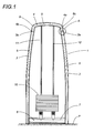
- the frame 1 in question is part of an isotonic exercise machine, which machine is not shown herein with reference to its other accessory parts, since they are known and not comprised in the invention.
- the frame 1 comprises a pair of uprights 2 and 3 substantially identical and mutually connected, in correspondence with respective upper ends, by an upper cross member 4, and, in correspondence with a respective lower end, by a lower cross member 6.
- the uprights 2 and 3 are slightly arched outwards, thereby conferring greater stability to the frame 1: in practice the uprights 2 and 3, together with the cross member 4, have outwardly concave development.
- the frame 1 is symmetrical with respect to an axis (not shown) that is substantially vertical and equidistant from the uprights 2 and 3, and is substantially shaped as a "portal".
- the weight pack 10 is able to slide, in the two directions, on the vertical bars 11 and 12 and can be actuated by the user through a pulley and flexible cable transmission (not shown herein) supported by the frame 1.
- the weight pack 10 is positioned in the lower part of the frame, but it can be positioned at different heights with respect to a treadable plane P, without any loss of originality in the present description.
- the uprights 2 and 3 and the aforesaid upper cross member 4 are realized with a respective first tubular bar 5 with rounded cross section, similar to a flattened circular section. Without detracting from the originality of the present description, the section of the first tubular bar 5 can be defined as oval.
- Fig. 1 also shows, to complete the frame 1, a lower cross member 6, bilaterally connected to the pair of uprights 2 and 3 and preferentially comprising a second tubular bar 7 with oval section geometrically similar to the first tubular bar 5.
- this second tubular bar 7 presents an essentially identical cross section to that of the first tubular bar 5.
- the pair of uprights 2 and 3 and the upper cross member 4 can be obtained in a single type of tubular cross member with oval/elliptical cross section, i.e. these elements are obtained from the same base section bar.
- the architecture of the uprights 2 and 3 presents an arched and mutually opposite development, when the frame 1 is assembled, and the upper cross member 4 is also arched: in this way a portal is created that is shaped as an upside down "U” with rounded edges, closed at the bottom by the lower cross member 6.
- each isotonic machine is designed with the purpose of training a determined muscle district; hence, the vertical extension of the uprights 2 and 3 will be proportionate to the amount of mass necessary to train the muscle set.
- the uprights 2 and 3 of a leg press will have greater extension than that of the uprights of a pectoral muscle press.
- the width of the portal, as well as the curvature / arch radius of the uprights 2 and 3 and of the cross member 4 may be proportioned accordingly.
- Fig. 3 shows that between the extremities 4a and 4b of the aforesaid upper cross member 4 and the respective upper extremities 2a and 3a of the pair of uprights 2 and 3, means 8 are provided for rapid coupling, for instance by snapping, in correspondence with the junctions 9 of the upper cross member 4 with the pair of uprights 2 and 3.
- these rapid coupling means 8 may be constituted by a bayonet coupling device comprising a plurality of retractable teeth 20 positioned on a related end section 21 realized on the corresponding extremity 4a and 4b of the upper cross member 4 and presenting smaller size with respect to the size of the corresponding extremity 2a and 3a of the uprights 2 and 3.
- the coupling of the cross member 4 (according to the direction F) on the uprights 2 and 3 is assured thanks to corresponding internal projections 22 present on the uprights 2 and 3, which determine an initial inward motion of the teeth 20 during the insertion of the cross member 4 and a subsequent stop against the teeth themselves, in the advanced position, upon completion of the coupling operation.
- the frame 1 is equivalent to a frame obtained by bending with variable radius from a single tubular bar with oval section. In this way the junctions 9 would be realized automatically during the bending operation itself.
- the "portal" frame 1, that is the uprights 2, 3 and the upper cross member 4 could be realized as a whole starting from a single tubular bar (having an oval cross section) which is bent in correspondence of the curved portions indicated with the reference 9c.
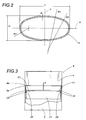
- the oval shape (which could also be defined by an ellipse) is preferentially definable as per Fig. 2, in which the greater and respectively smaller axes X, Y define the values of length L and width H.
- Fig. 2 also shows three values of radius of curvature that realize, in their combination, the resulting oval combination: these radii are R1, the smallest, R2 the intermediate one and R3 the largest.
- the thickness S of the tubular bar itself can lie within a range of values from 1 to 4 mm, and it preferably shall be 2.5 mm.
- the choice of an oval section for the constructive elements of the frame 1 allows to reduce the specific weight of the structure (computed on the basis of the length of the axis of the tubular elements) maintaining at least unchanged the mechanical resistance of the structure to the loads oriented according to the direction of elongation of the oval section itself.
- the frame 1 presents greater rigidity than a quadrangular section of substantially identical weight (and thus presenting greater thickness). Maintaining constant the specific weight computed with respect to the length of the tubular bars and increasing the internal volumes to the uprights 2 and 3, it is also possible to increase mechanical strength, at the same time reducing thickness.
- the enhanced rigidity and mechanical strength, and the simultaneous weight limitation, also allow to obtain isotonic machines with frames 1 that are less bulky and free of stiffening arms. These machines are thus easy to move and safer, presenting fewer projections and hindrances to the users' access.
- the gradual variation of the curvature radii of the sections of the cross members and of the axes of the uprights 2 and 3 limits dust accumulation, facilitating cleaning operations.
- the frame 1 from the constructive standpoint as a plurality of individual lengths mutually connected in a rigid manner (and also because of the reduced value of thickness of the uprights 2 and 3 and cross members 4 and 6), in the frame 1 the geometric axes of the adjacent lengths of tube will substantially coincide with the axis of transmission of the stress acting under load. Since the stresses that the adjacent lengths transmit to each other are substantially normal stresses, the frames will be particularly well balanced under load thanks to the substantial absence of transverse loads.
- the large inner section of the tubular bars obtained with the oval/elliptical conformation, allows conveniently to house accessory elements, such as electrical wires, driving cables, pulleys, etc., without having to occupy space outside the frame.
- accessory elements such as electrical wires, driving cables, pulleys, etc.
- the internal positioning of these accessories allows to simplify the structure of the machine and to make it easily accessible to the user without his/her having to walk over metal or electrical cables.
- the possible reversible coupling of the upper cross member allows to obtain an easier access to the interior part of the tubular bars comprising the frame for any ordinary or extraordinary maintenance operations.
Applications Claiming Priority (2)
| Application Number | Priority Date | Filing Date | Title |
|---|---|---|---|
| ITBO980375 | 1998-06-16 | ||
| IT1998BO000375A IT1304009B1 (it) | 1998-06-16 | 1998-06-16 | Telaio per macchine ginniche. |
Publications (2)
| Publication Number | Publication Date |
|---|---|
| EP0965365A2 true EP0965365A2 (de) | 1999-12-22 |
| EP0965365A3 EP0965365A3 (de) | 2000-05-31 |
Family
ID=11343247
Family Applications (1)
| Application Number | Title | Priority Date | Filing Date |
|---|---|---|---|
| EP99830362A Withdrawn EP0965365A3 (de) | 1998-06-16 | 1999-06-11 | Rahmen für Übungsgeräte |
Country Status (2)
| Country | Link |
|---|---|
| EP (1) | EP0965365A3 (de) |
| IT (1) | IT1304009B1 (de) |
Cited By (1)
| Publication number | Priority date | Publication date | Assignee | Title |
|---|---|---|---|---|
| WO2004014493A1 (de) * | 2002-07-28 | 2004-02-19 | Sonja Stromberg | Profil für rahmen von fitness- und gesundheitsgeräte |
Family Cites Families (6)
| Publication number | Priority date | Publication date | Assignee | Title |
|---|---|---|---|---|
| DE1927580A1 (de) * | 1969-05-30 | 1970-11-19 | Velox Werke Herbert Schnelle | Moebel mit Gestellen aus Hohlprofil |
| US5622527A (en) * | 1986-05-08 | 1997-04-22 | Proform Fitness Products, Inc. | Independent action stepper |
| DE3931478C1 (en) * | 1989-09-21 | 1991-04-04 | Deutsche Forschungsanstalt Fuer Luft- Und Raumfahrt Ev, 5300 Bonn, De | Triangular tubular frame - is made of circular or elliptical section plastics tubes fastened together |
| GB9023652D0 (en) * | 1990-10-31 | 1990-12-12 | Calvert Philip | Improvements in or relating to exercise apparatus |
| US5727764A (en) * | 1996-03-22 | 1998-03-17 | Lifegear, Inc. | Self-locking quick release bracket |
| US5716304A (en) * | 1996-05-07 | 1998-02-10 | Greenmaster Industrial Corp. | Elliptical frame structure for exercise bikes |
-
1998
- 1998-06-16 IT IT1998BO000375A patent/IT1304009B1/it active
-
1999
- 1999-06-11 EP EP99830362A patent/EP0965365A3/de not_active Withdrawn
Non-Patent Citations (1)
| Title |
|---|
| None |
Cited By (1)
| Publication number | Priority date | Publication date | Assignee | Title |
|---|---|---|---|---|
| WO2004014493A1 (de) * | 2002-07-28 | 2004-02-19 | Sonja Stromberg | Profil für rahmen von fitness- und gesundheitsgeräte |
Also Published As
| Publication number | Publication date |
|---|---|
| ITBO980375A1 (it) | 1999-12-16 |
| EP0965365A3 (de) | 2000-05-31 |
| IT1304009B1 (it) | 2001-03-02 |
Similar Documents
| Publication | Publication Date | Title |
|---|---|---|
| US9114273B2 (en) | Exercise device | |
| US4993706A (en) | Exercise bench | |
| EP2149392A1 (de) | Übungsgerät mit Stepper- und Drehbewegung | |
| US20030060345A1 (en) | Weight systems for exercise equipment | |
| EP0965365A2 (de) | Rahmen für Übungsgeräte | |
| US6558300B2 (en) | Weight stack for exercise machine | |
| US4883145A (en) | Ergonomic aerial basket | |
| JPH0226572A (ja) | 筋肉鍛練用ボデイ・トレーニングマシン | |
| CN211705748U (zh) | 一种多功能健身器材 | |
| CN212214498U (zh) | 一种律动机拉伸装置 | |
| CN209556910U (zh) | 一种电线杆攀爬梯 | |
| ITTO980046U1 (it) | Attrezzatura per esercizi ginnici. | |
| CN213912129U (zh) | 一种多功能单站位训练器 | |
| CN212347585U (zh) | 一种健身操辅助器械 | |
| CN214479123U (zh) | 一种组合式省力电缆挂件 | |
| CN210551118U (zh) | 取料架及包括其的新能源车辆生产线 | |
| CN216436643U (zh) | 一种槽式电缆桥架布线辅助装置 | |
| CN210873956U (zh) | 一种臂力拉伸训练装置 | |
| CN213096549U (zh) | 一种撑伞装置 | |
| RU122028U1 (ru) | Тренажер спортивный многофункциональный | |
| CN201029665Y (zh) | 带导轨蚊帐 | |
| RU39279U1 (ru) | Тренажер для тренировки мышц и суставов | |
| US3378979A (en) | Mountable latticework | |
| CN114007704A (zh) | 悬挂式安装和锻炼装置及其使用方法 | |
| EP0479797A1 (de) | Schiebeleiter. |
Legal Events
| Date | Code | Title | Description |
|---|---|---|---|
| PUAI | Public reference made under article 153(3) epc to a published international application that has entered the european phase |
Free format text: ORIGINAL CODE: 0009012 |
|
| AK | Designated contracting states |
Kind code of ref document: A2 Designated state(s): BE CH DE ES FR GB IT LI LU NL |
|
| AX | Request for extension of the european patent |
Free format text: AL;LT;LV;MK;RO;SI |
|
| PUAL | Search report despatched |
Free format text: ORIGINAL CODE: 0009013 |
|
| AK | Designated contracting states |
Kind code of ref document: A3 Designated state(s): AT BE CH CY DE DK ES FI FR GB GR IE IT LI LU MC NL PT SE |
|
| AX | Request for extension of the european patent |
Free format text: AL;LT;LV;MK;RO;SI |
|
| RIC1 | Information provided on ipc code assigned before grant |
Free format text: 7A 63B 21/062 A |
|
| RIN1 | Information on inventor provided before grant (corrected) |
Inventor name: CAMELLI, MARCO Inventor name: ALESSANDRI, NERIO |
|
| 17P | Request for examination filed |
Effective date: 20001122 |
|
| AKX | Designation fees paid |
Free format text: BE CH DE ES FR GB IT LI LU NL |
|
| 17Q | First examination report despatched |
Effective date: 20031209 |
|
| STAA | Information on the status of an ep patent application or granted ep patent |
Free format text: STATUS: THE APPLICATION IS DEEMED TO BE WITHDRAWN |
|
| 18D | Application deemed to be withdrawn |
Effective date: 20040420 |