EP0933503A2 - Silencer for a gas turbine exhaust channel - Google Patents
Silencer for a gas turbine exhaust channel Download PDFInfo
- Publication number
- EP0933503A2 EP0933503A2 EP99100914A EP99100914A EP0933503A2 EP 0933503 A2 EP0933503 A2 EP 0933503A2 EP 99100914 A EP99100914 A EP 99100914A EP 99100914 A EP99100914 A EP 99100914A EP 0933503 A2 EP0933503 A2 EP 0933503A2
- Authority
- EP
- European Patent Office
- Prior art keywords
- gas turbine
- flow
- silencer according
- elements
- section
- Prior art date
- Legal status (The legal status is an assumption and is not a legal conclusion. Google has not performed a legal analysis and makes no representation as to the accuracy of the status listed.)
- Withdrawn
Links
Images
Classifications
-
- F—MECHANICAL ENGINEERING; LIGHTING; HEATING; WEAPONS; BLASTING
- F01—MACHINES OR ENGINES IN GENERAL; ENGINE PLANTS IN GENERAL; STEAM ENGINES
- F01D—NON-POSITIVE DISPLACEMENT MACHINES OR ENGINES, e.g. STEAM TURBINES
- F01D25/00—Component parts, details, or accessories, not provided for in, or of interest apart from, other groups
- F01D25/30—Exhaust heads, chambers, or the like
Definitions
- the invention relates to a silencer for a Gas turbine plant, as used in particular for energy generation is used with stationary systems.
- Modern power plants use at least steam generation partly gas turbine systems that are not only mechanical, energy that can be directly used by generators, but also emit a hot gas stream that can be used to generate energy via steam generators.
- gas turbine systems replace conventional firing systems completely or partially.
- Gas turbines point relatively at their outlet (exhaust) high gas speeds. Besides, that is Flow at least partially very turbulent and the Gas turbine gives a high sound level at its outlet from.
- the high flow rate at the exit of the Gas turbine has a very low static pressure Episode.
- a diffuser is usually used for this, which is characterized by a long, gradually widening channel is formed. To the To achieve the desired diffuser effect, the opening angle of the expanding channel not too big be. With the required cross sectional enlargements of the Flow channel leads this with common diffuser inlet cross sections to lengths of more than 10 m, e.g. 13 m.
- the invention solves this problem with a gas turbine silencer with the features of the claim 1.
- the gas turbine diffuser is part of the Silencer.
- This is achieved by the interior of the muffler by setting elements in preferably side by side diffuser channels is divided. These open in the flow direction, respectively the flow cross-section even at small opening angles relatively strong in percentage terms in each diffuser channel increases.
- the increase is significantly larger than one single diffuser channel with the same opening angle and correspondingly larger inlet cross-section. To this In this way, a double gain in space is achieved.
- a large Space is gained through the structural union of diffuser and muffler together.
- Another Significant shortening of the overall length is due to the division of the flow channel to many parallel, i.e. Diffuser channels connected to one another on the inlet and outlet side reached.
- the interior of the housing of the gas turbine silencer is through individual backdrop elements in diffuser channels divided.
- the backdrop elements effect one Orientation of the flow by following the flow path pretend.
- the backdrop elements for example.
- As a steel frame be built up with ceramic fibers is. It results from the structure of the ceramic mesh additionally a sound absorbing effect.
- the housing for example, at least partially on the inside with ceramic fabric be lined up for sound transmission to dampen outside.
- the backdrop elements preferably designed as a flow body, the gas flow has the lowest possible resistance oppose and if possible no additional vertebrae produce.
- the backdrop elements can, for example, as Plates should be formed, the thickness of which is upstream increases towards the downstream end, and the both on their upstream and on their downstream Are rounded at the end.
- the diffuser channels are, for example, slit-like trained, i.e. the fault cross section is indicated by a narrow rectangle formed, the short edge of which is downstream increases while the longer edge remains unchanged remains. In this way, with small opening angles, which allow a good diffuser effect, a percentage, relatively high, increase in cross section.
- the backdrop elements can also be a constant or different in the direction of flow have changing, for example decreasing thickness.
- the link elements can be ring-shaped, for example be designed as round or square elements. Again, it is possible to make the diffuser channels relative form narrow gaps, their thickness in the direction of flow increases. Thus, a good diffuser effect is short Length allowed.
- the backdrop elements are preferred in side view Rectangular plates with a horizontal flow direction in the gas turbine silencer essentially are arranged vertically.
- the backdrop elements are preferably held firmly on their underside. At their upper end they are only fixed laterally, moving up and down can. This avoids tension when heating up quickly and cooling. Especially when starting the gas turbines there is a very quick warm-up process. Through the one-sided mounting of the link elements becomes temperature tensions minimized.
- a grid is arranged, which with the 80 to 150 m / s divides flow delivered by the gas turbine.
- a grid element in each case a link element with, for example, a round cross section.
- the Lattice bar is at a distance of a few centimeters arranged in front of the front edge of the respective link element.
- the one as a flow divider or vortex breaker serving staff creates a slipstream, so to speak in which a set element is then arranged. The resulting flow resistance is less than for arrangements without flow dividers.
- the backdrop elements arranged obliquely (angle ⁇ ) to each other, but they are even wedge-shaped, that is, from the entrance to the exit thicker. This results in a good superimposition of the muffler effect with the diffuser effect and at the same time advantageous slow flow conditions at the exit.
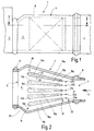
- a gas turbine silencer 1 is illustrated in FIG. 1, the one at the exit is only schematic and cut indicated gas turbine 2 one stationary power plant is connected and to a likewise only schematically and cut indicated steam generator 3 leads.
- the gas turbine silencer 1 serves the gas turbine 2 with leaving a speed of over 100 m / s Exhaust gases to calm down and slow them down with a Speed below 30 meters per second to the steam generator 3 deliver.
- the gas turbine silencer has 1 a housing 4 which encloses an interior 5. To avoid unwanted cooling the flowing through the gas turbine muffler 1 Exhaust gases from the gas turbine 2 is the housing 4 with a Insulating layer 6 provided for thermal insulation.
- the housing 4 like the side view in Figure 1 illustrates an almost constant height. However, the width of the housing 4 increases from that Gas turbine 2 to the steam generator 3, in particular Figure 2 illustrates.
- the housing 4 is at the gas turbine end provided with an entrance 7, the cross section of which is rectangular is. At the input 7 there is a compensator 8 arranged, the elastic expansion resiliently compensates.
- the compensator connects the output of the gas turbine 2 fluid-tight with the input 7 of the housing 4.
- the housing 4 is for connection to the steam generator 3 provided with an output 9 through a rectangular opening is also formed.
- a compensator 11 is arranged, the thermal conditional extensions between the steam generator 3 and balance the housing 4.
- the Link elements 14 are essentially mutually identically constructed, approximately plate-shaped elements that a steel frame with ceramic fiber layer.
- the Set elements 14 are standing in the interior 5 arranged and subdivide the interior 5 of one flow channel extending from the inlet 7 to the outlet 9 forms, into individual diffuser channels 15 (15a to 15f)
- the diffuser channels 15 are relatively narrow. While at its entrance, for example, a height of 4000 millimeters can have, they are only about 200 millimeters wide. They are therefore slit or slit-shaped.
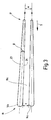
- the individual diffuser elements in the direction of flow i.e. from their respective upstream End 17 towards its downstream end 18 thicker.
- Adjacent diffuser elements 14 are each enclosing an acute angle ⁇ arranged, which is preferably less than 7 °.
- the diffuser channel 15 expands accordingly fewer. Nevertheless, the percentage is high Increase in flow cross-section and thus a good one Slowdown and increase in pressure of the flowing Gas flow reached. Without scenery elements 14, the expanding interior 5 due to the muffler the divergence angle of the two side walls of the housing 4 of about 30 ° no longer act as a diffuser.
- the link elements 14 thus perform a double function. On the one hand, they define between each other Diffuser channels 15, on the other hand, they align the Gas turbine 2 incoming turbulent flow from and even out these.
- the diffuser element 14 has essentially flat side surfaces 23, 24 (FIG. 3) which together form an acute angle ⁇ . This is only a few degrees (for example 3 to 5 °). At its front or upstream end, the link element 14 is rounded off with a radius. Likewise, the link element 14 is rounded at its downstream or rear end 18 with a radius.
- each lattice bar 22 is a link element 14 assigned and at some distance from this arranged. The distance corresponds approximately to the thickness of the relevant backdrop element in the middle between its upstream end 17 and its downstream End 18.
- the bars have a round cross-section and are parallel to the backdrop elements aligned, i.e. they are to be thought in or in parallel Layers arranged by the side surfaces 23, 24 each Setting element 14 are set.
- an empty space serves as an exit space 25.
- the entry room 25 forms a branch in which the diffuser channels 15 are connected to each other on the input side forms the Exit area a merger or a collection area for the gases emerging from the diffuser channels 15.
- the gas turbine silencer 1 described so far works as follows:
- the gas turbine 2 comes into operation in the direction of flow S is a gas flow at high speed from, for example, 100 to 120 m / s.
- the gas flow occurs the entrance room 21 and first meets the Lattice bars 22.
- the flow is divided to itself to those defined between the backdrop elements 14 Split diffuser channels 15.
- the flow due to the small distances between the link elements 14 with each other on an essentially straight path forced and thus evened out.
- the pressure static Pressure
- the partial gas flows combine in the outlet space 25 of the diffuser channels 15a to 15f to form a total gas flow and exit at exit 9. This is correct essentially with the sum of the individual cross sections on the output side of the diffuser channels 15 match.
- the gas turbine silencer 1 has one in the flow direction S. a relatively large angle widening interior 5.
- This backdrop elements 14 are arranged between each other Diffuser channels 15 limit themselves each with a much smaller acute angle expand from below 7 °.
- the narrow, gap-like diffuser channels 15 cause, in addition to slowing down Gas flow and thus in addition to an increase in pressure noise reduction by reducing turbulence and an equalization and alignment of the Flow. Thanks to the additional function of the gas turbine silencer 1 as a diffuser can be required so far separate diffusers that take up a large amount of space have been eliminated.
Abstract
Description
Die Erfindung betrifft einen Schalldämpfer für eine Gasturbinenanlage, wie sie insbesondere zur Energieerzeugung mit stationären Anlagen verwendet wird.The invention relates to a silencer for a Gas turbine plant, as used in particular for energy generation is used with stationary systems.
Moderne Kraftwerke nutzen zur Dampferzeugung wenigstens teilweise Gasturbinenanlagen, die nicht nur mechanische, mittels Generatoren direkt verwertbare Energie, sondern darüber hinaus einen heißen Gasstrom abgeben, der über Dampferzeuger zur Energieerzeugung nutzbar ist. Die Gasturbinenanlagen ersetzten insoweit herkömmliche Feuerungsanlagen ganz oder teilweise. Modern power plants use at least steam generation partly gas turbine systems that are not only mechanical, energy that can be directly used by generators, but also emit a hot gas stream that can be used to generate energy via steam generators. The In this respect, gas turbine systems replace conventional firing systems completely or partially.
Gasturbinen weisen an ihrem Ausgang (Auspuff) relativ hohe Gasgeschwindigkeiten auf. Außerdem ist die Strömung wenigstens teilweise stark turbulent und die Gasturbine gibt an ihrem Ausgang einen hohen Schallpegel ab. Die hohe Strömungsgeschwindigkeit an dem Ausgang der Gasturbine hat einen sehr geringen statischen Druck zur Folge. In der Regel ist es erforderlich, die Gasströmung zugunsten des statischen Drucks deutlich zu verlangsamen. Dazu dient meist ein Diffusor, der durch einen langen, sich allmählich erweiternden Kanal gebildet wird. Um die gewünschte Diffusorwirkung zu erzielen, darf der Öffnungswinkel des sich erweiternden Kanals nicht zu groß sein. Bei den geforderten Querschnittsvergrößerungen des Strömungskanals fuhrt dies bei gängigen Diffusoreintrittsguerschnitten zu Baulängen von deutlich über 10 m, bspw. 13 m.Gas turbines point relatively at their outlet (exhaust) high gas speeds. Besides, that is Flow at least partially very turbulent and the Gas turbine gives a high sound level at its outlet from. The high flow rate at the exit of the Gas turbine has a very low static pressure Episode. As a rule, it is necessary the gas flow to slow down significantly in favor of static pressure. A diffuser is usually used for this, which is characterized by a long, gradually widening channel is formed. To the To achieve the desired diffuser effect, the opening angle of the expanding channel not too big be. With the required cross sectional enlargements of the Flow channel leads this with common diffuser inlet cross sections to lengths of more than 10 m, e.g. 13 m.
Wenn der statische Druck des Gasstroms durch gezielte Verlangsamung in dem Diffusor erhöht worden ist, ist jedoch nach wie vor ein erheblicher Schallpegel vorhanden, den es zu vermindern gilt. Deshalb sind bei herkömmlichen Gasturbinenanlagen meist Schalldämpfer vorgesehen, die sich an den jeweiligen Diffusor anschliessen. Insgesamt ergibt sich somit im Anschluss an die Gasturbine eine relativ voluminöse, aus Diffusor und nachgeschaltetem Schalldämpfer bestehende Anlage. Diese Anlage nimmt nicht nur wertvollen Bauraum ein, sondern hat in der Regel einen unerwünscht hohen Rückstau oder Druckverlust. Dieser vermindert die mechanische Energieausbeute der Gasturbine.When the static pressure of the gas flow through targeted Slowdown in the diffuser has been increased however, there is still a significant level of noise, which has to be reduced. That is why with conventional Gas turbine systems mostly provided silencers, which connect to the respective diffuser. All in all thus results after the gas turbine a relatively voluminous, made up of diffuser and downstream Exhaust system existing. This facility is taking not only a valuable installation space, but has in the Usually an undesirably high back pressure or pressure loss. This reduces the mechanical energy yield of the Gas turbine.
Hier setzt die Erfindung an, deren Aufgabe es ist, die zum Betrieb der Gasturbine erforderlichen Anlagenteile so zu gestalten, dass diese möglichst wenig Bauraum beanspruchen. Außerdem soll die mechanische Leistung der Gasturbine möglichst wenig beeinträchtigt werden. This is where the invention comes in, the task of which is the parts of the system required to operate the gas turbine to be designed so that there is as little installation space as possible claim. In addition, the mechanical performance of the Gas turbine are affected as little as possible.
Diese Aufgabe löst die Erfindung durch einen Gasturbinenschalldämpfer mit den Merkmalen des Patentanspruchs 1.The invention solves this problem with a gas turbine silencer with the features of the claim 1.
Erfindungsgemäß ist der Diffusor der Gasturbine Teil des Schalldämpfers. Dies wird erreicht, indem der Innenraum des Schalldämpfers durch Kulissenelemente in vorzugsweise nebeneinander angeordnete Diffusorkanäle unterteilt wird. Diese öffnen sich jeweils in Strömungsrichtung, wobei auch bei geringen Öffnungswinkeln der Strömungsquerschnitt in jedem Diffusorkanal prozentual relativ stark zunimmt. Die Zunahme ist deutlich größer als bei einem einzigen Diffusorkanal gleichen Öffnungswinkels und entsprechend größeren Eintrittsquerschnitts. Auf diese Weise wird ein doppelter Platzgewinn erreicht. Ein großer Platzgewinn ergibt sich durch die bauliche Vereinigung von Diffusor und Schalldampfer miteinander. Eine weitere wesentliche Verkürzung der Baulänge wird durch die Aufteilung des Strömungskanals auf viele parallele, d.h. ein- und ausgangsseitig miteinander verbundene Diffusorkanäle erreicht. War für herkömmliche Gasturbinenschalldämpfer- und Diffusoranlagen eine Gesamtbaulänge von zwischen 10 und 15 m erforderlich, kommt der erfindungsgemäße Gasturbinenschalldämper, der zugleich Diffusorfunktion übernimmt, mit einer Baulänge von 4 bis 5 m aus. Verständlicherweise können sich entsprechend der gewünschten Leistung größere oder kleinere Abmessungen ergeben, wobei das Verhältnis der Abmessungen bekannter Anlagen zu dem erfindungsgemäßen Gasturbinenschalldämpfer ähnlich bleibt. Die verminderten Gesamtabmessungen erleichtern die Wärmeisolation und vermindern schon durch die verringerte Oberfläche der Anlage die Wärmeverluste.According to the invention, the gas turbine diffuser is part of the Silencer. This is achieved by the interior of the muffler by setting elements in preferably side by side diffuser channels is divided. These open in the flow direction, respectively the flow cross-section even at small opening angles relatively strong in percentage terms in each diffuser channel increases. The increase is significantly larger than one single diffuser channel with the same opening angle and correspondingly larger inlet cross-section. To this In this way, a double gain in space is achieved. A large Space is gained through the structural union of diffuser and muffler together. Another Significant shortening of the overall length is due to the division of the flow channel to many parallel, i.e. Diffuser channels connected to one another on the inlet and outlet side reached. Was a total length of conventional gas turbine muffler and diffuser systems required between 10 and 15 m, comes the invention Gas turbine silencer that also acts as a diffuser takes over, with a length of 4 to 5 m. Understandably, you can choose the one you want Performance larger or smaller dimensions result, the ratio of the dimensions of known Plants for the gas turbine silencer according to the invention remains similar. The reduced overall dimensions facilitate the heat insulation and already diminish through the reduced surface of the system the heat loss.
Durch die bauliche und funktionelle Vereinigung von Schalldämpfer und Diffusor fällt eine Übergangsstelle zwischen dem Schalldämpfer und dem Diffusor weg, wie sie bisher vorhanden gewesen ist. Solche Übergangsstellen können aufgrund des sich hier ändernden Strömungswiderstands einen Druckverlust erzeugen, der von der Gasturbine überwunden werden muss und somit deren Leistungsausbeute mindert. Dies ist bei dem erfindungsgemaßen Gasturbinenschalldämpfer vermieden. Gegenüber herkömmlichen Anlagen kann sich ein Druckgewinn von 2 bis 3 mbar ergeben.Through the structural and functional union of Muffler and diffuser fall a transition point between the muffler and the diffuser away as they has been present so far. Such transition points can change due to the changing flow resistance generate a pressure drop from the gas turbine must be overcome and thus their performance diminishes. This is the case with the gas turbine silencer according to the invention avoided. Compared to conventional ones Systems can result in a pressure gain of 2 to 3 mbar.
Der Innenraum des Gehäuses des Gasturbinenschalldämpfers ist durch einzelne Kulissenelemente in Diffusorkanäle unterteilt. Die Kulissenelemente bewirken eine Ausrichtung der Strömung, indem sie den Strömungsweg vorgeben. Um der auftretenden thermischen Belastung zu widerstehen, können die Kulissenelemente bspw. als Stahlgerippe aufgebaut sein, das mit Keramikfasern versehen ist. Es ergibt sich durch die Struktur des Keramikgewebes zusätzlich eine schalldämpfende Wirkung. Außerdem kann das Gehäuse bspw. innen wenigstens teilweise mit Keramikgewebe ausgekleidet sein, um die Schallübertragung nach außen zu dämpfen.The interior of the housing of the gas turbine silencer is through individual backdrop elements in diffuser channels divided. The backdrop elements effect one Orientation of the flow by following the flow path pretend. To the occurring thermal load too resist, the backdrop elements, for example. As a steel frame be built up with ceramic fibers is. It results from the structure of the ceramic mesh additionally a sound absorbing effect. Besides, can the housing, for example, at least partially on the inside with ceramic fabric be lined up for sound transmission to dampen outside.
Ungeachtet des verwendeten Materials sind die Kulissenelemente vorzugsweise als Strömungskörper ausgebildet, die der Gasströmung einen möglichst geringen Widerstand entgegensetzen und möglichst keine zusätzlichen Wirbel erzeugen. Die Kulissenelemente können dabei bspw. als Platten ausgebildet sein, deren Dicke von dem stromaufwärtigen zu dem stromabwärtigen Ende hin zunimmt, und die sowohl an ihrem stromaufwärtigen als an ihrem stromabwärtigen Ende abgerundet sind. Trotz der Zunahme der Dicke der Strömungskörper in Strömungsrichtung, bleiben zwischen den Kulissenelementen Zwischenräume, (Diffusorkanäle) deren Strömungsquerschnitt in Strömungsrichtung zunimmt. Die Diffusorkanäle sind bspw. schlitzartig ausgebildet, d.h. der Störmungsquerschnitt wird durch ein schmales Rechteck gebildet, dessen kurze Kante stromabwärts zunimmt, während die längere Kante unverändert bleibt. Auf diese Weise wird bei geringen Öffnungswinkeln, die eine gute Diffusorwirkung ermöglichen, eine prozentuale, relative hohe, Querschnittszunahme ermöglicht. Bedarfsweise können die Kulissenelemente auch eine gleichbleibende oder sich in Strömungsrichtung anderweitig ändernde, bspw. abnehmende Dicke aufweisen.Regardless of the material used, the backdrop elements preferably designed as a flow body, the gas flow has the lowest possible resistance oppose and if possible no additional vertebrae produce. The backdrop elements can, for example, as Plates should be formed, the thickness of which is upstream increases towards the downstream end, and the both on their upstream and on their downstream Are rounded at the end. Despite the increase in thickness the flow body in the flow direction, remain between the backdrop elements gaps (diffuser channels) whose flow cross-section in the direction of flow increases. The diffuser channels are, for example, slit-like trained, i.e. the fault cross section is indicated by a narrow rectangle formed, the short edge of which is downstream increases while the longer edge remains unchanged remains. In this way, with small opening angles, which allow a good diffuser effect, a percentage, relatively high, increase in cross section. If necessary, the backdrop elements can also be a constant or different in the direction of flow have changing, for example decreasing thickness.
Alternativ können die Kulissenelemente bspw. ringförmig als runde oder eckige Elemente ausgebildet sein. Auch hier ist es möglich, die Diffusorkanäle als relativ enge Spalte auszubilden, deren Dicke in Strömungsrichtung zunimmt. Somit wird eine gute Diffusorwirkung bei kurzer Baulänge ermöglicht.Alternatively, the link elements can be ring-shaped, for example be designed as round or square elements. Again, it is possible to make the diffuser channels relative form narrow gaps, their thickness in the direction of flow increases. Thus, a good diffuser effect is short Length allowed.
Bei einer vorteilhaften Ausführungsform stimmt die Summe der eingangsseitigen Strömungsquerschnitte der Diffusorkanäle mit dem Strömungsquerschnitt des Eingangs des Gasturbinenschalldämpfers im Wesentlich überein oder ist entsprechend auf diesen abgestimmt. Dies vermeidet Druckverluste unabhängig davon, ob der Eingang einen rechteckigen oder einen runden Querschnitt aufweist. Ist der Querschnitt rund, kann es vorteilhaft sein, wenn der resultierende Strömungsquerschnitt, der sich aus der Summe der eingangsseitigen Querschnitte der Diffusorkanäle ergibt, etwas größer ist als der Querschnitt des Eingangs.In an advantageous embodiment, that is correct Sum of the flow cross sections of the inlet Diffuser channels with the flow cross-section of the entrance of the gas turbine muffler essentially match or is coordinated accordingly. This avoids Pressure drops regardless of whether the input is a has a rectangular or a round cross section. Is the cross section round, it may be advantageous if the resulting flow cross-section, which results from the Sum of the cross-sections of the diffuser channels on the input side is slightly larger than the cross section of the Input.
Die Kulissenelemente sind in Seitenansicht vorzugsweise Rechteckplatten, die bei horizontaler Durchströmungsrichtung in dem Gasturbinenschalldämpfer im Wesentlichen vertikal angeordnet sind. Die Kulissenelemente sind dabei vorzugsweise an ihrer Unterseite fest gehalten. An ihrem oberen Ende sind sie lediglich seitlich fixiert, wobei sie sich nach oben und nach unten bewegen können. Dies vermeidet Spannungen bei schnellem Aufheizen und Abkühlen. Insbesondere beim Starten der Gasturbinen ergibt sich ein sehr schneller Aufwärmvorgang. Durch die einseitige Halterung der Kulissenelemente werden Temperaturspannungen minimiert. The backdrop elements are preferred in side view Rectangular plates with a horizontal flow direction in the gas turbine silencer essentially are arranged vertically. The backdrop elements are preferably held firmly on their underside. At their upper end they are only fixed laterally, moving up and down can. This avoids tension when heating up quickly and cooling. Especially when starting the gas turbines there is a very quick warm-up process. Through the one-sided mounting of the link elements becomes temperature tensions minimized.
Zur Anpassung der Strömungsquerschnitte in dem Diffusorbereich an dem Ein- und Ausgang ist vorzugsweise sowohl vor den Kulissenelementen als auch danach ein jeweiliger Anpassraum, d.h. ein Eintrittsraum und ein Austrittsraum angeordnet. In dem Eintrittsraum ist vorzugsweise ein Gitter angeordnet, das die mit 80 bis 150 m/s von der Gasturbine gelieferte Strömung teilt. Dabei ist vorzugsweise jeweils einem Kulissenelement ein Gitterstab mit bspw. rundem Querschnitt zugeordnet. Der Gitterstab ist in einem Abstand von einigen Zentimetern vor der Stirnkante des jeweiligen Kulissenelements angeordnet. Der als Strömungsteiler oder Wirbelbrecher dienende Stab erzeugt gewissermaßen einen Windschatten, in dem dann jeweils ein Kulissenelement angeordnet ist. Der sich ergebende Strömungswiderstand ist geringer als bei Anordnungen ohne Strömungsteiler.To adjust the flow cross sections in the Diffuser area at the entrance and exit is preferred both in front of the backdrop elements and afterwards respective adjustment room, i.e. an entry room and a Exit space arranged. In the entry room is preferred a grid is arranged, which with the 80 to 150 m / s divides flow delivered by the gas turbine. Here is preferably a grid element in each case a link element with, for example, a round cross section. Of the Lattice bar is at a distance of a few centimeters arranged in front of the front edge of the respective link element. The one as a flow divider or vortex breaker serving staff creates a slipstream, so to speak in which a set element is then arranged. The resulting flow resistance is less than for arrangements without flow dividers.
Vorzugsweise sind nicht nur die Kulissenelemente schräg (Winkel α) zueiander angeordnet, sondern sie sind selbst keilförmige, werden also vom Eingang zum Ausgang dicker. Dies ergibt eine gute Überlagerung der Schalldämpferwirkung mit der Diffusorwirkung und zugleich vorteilhafte langsame Strömungsverhälnisse am Ausgang.Preferably not only the backdrop elements arranged obliquely (angle α) to each other, but they are even wedge-shaped, that is, from the entrance to the exit thicker. This results in a good superimposition of the muffler effect with the diffuser effect and at the same time advantageous slow flow conditions at the exit.
Weitere Einzelheiten vorteilhafter Ausführungsformen
der Erfindung sind Gegenstand von Unteransprüchen und
ergeben sich aus der Zeichnung sowie der dazugehörigen
Beschreibung. In der Zeichnung ist ein Ausführungsbeispiel
der Erfindung veranschaulicht. Es zeigen:
In Figur 1 ist ein Gasturbinenschalldämpfer 1 veranschaulicht,
der an den Ausgang einer lediglich schematisch
und angeschnitten angedeuteten Gasturbine 2 einer
stationären Energieerzeugungsanlage angeschlossen ist und
zu einem ebenfalls lediglich schematisch und angeschnit-ten
angedeuteten Dampferzeuger 3 führt. Der Gasturbinenschalldämpfer
1 dient dazu, die die Gasturbine 2 mit
einer Geschwindigkeit von über 100 m/s verlassenden
Abgase zu beruhigen und zu verlangsamen, um sie mit einer
Geschwindigkeit unter 30 Meter pro Sekunde an den Dampferzeuger
3 abzugeben. Dazu weist der Gasturbinenschalldämpfer
1 ein Gehäuse 4 auf, das einen Innenraum 5 umschliesst.
Zur Vermeidung einer unerwünschten Auskühlung
der durch den Gasturbinenschalldämpfer 1 strömenden
Abgase der Gasturbine 2 ist das Gehäuse 4 mit einer
Isolierschicht 6 zur Wärmeisolation versehen.A gas turbine silencer 1 is illustrated in FIG. 1,
the one at the exit is only schematic
and cut indicated
Das Gehäuse 4 weist, wie die Seitenansicht in Figur
1 veranschaulicht, eine nahezu gleichbleibende Höhe auf.
Jedoch vergrößert sich die Breite des Gehäuses 4 von der
Gasturbine 2 zu dem Dampferzeuger 3 hin, wie insbesondere
Figur 2 veranschaulicht.The
An dem gasturbinenseitigen Ende ist das Gehäuse 4
mit einem Eingang 7 versehen, dessen Querschnitt rechteckförmig
ist. An dem Eingang 7 ist ein Kompensator 8
angeordnet, der Wärmedehnungen federnd nachgiebig aus-gleicht.
Der Kompensator verbindet den Ausgang der Gasturbine
2 mit dem Eingang 7 des Gehäuses 4 fluiddicht.
Außerdem ist das Gehäuse 4 zum Anschluss an den Dampferzeuger
3 mit einem Ausgang 9 versehen, der durch eine
ebenfalls rechteckige Öffnung gebildet wird. An dem
Ausgang 9 ist ein Kompensator 11 angeordnet, der thermisch
bedingte Verlàgerungen zwischen dem Dampferzeuger 3
und dem Gehäuse 4 ausgleichen. The
In dem Innenraum 5 des sich in Strömungsrichtung S
(siehe Pfeil in Figur 2) mit einem Öffnungswinkel von
ungefähr 30° erweiternden Gehäuses 4, sind mehrere Kulissenelemente
14 (14a bis 14e) angeordnet. Im vorliegenden
Fall sind insgesamt fünf Kulissenelemente vorgesehen,
wobei deren Zahl von Fall zu Fall variieren kann. Die
Kulissenelemente 14 sind untereinander im Wesentlichen
gleich aufgebaute, etwa plattenförmige Elemente, die aus
einem Stahlgerüst mit Keramikfaserauflage bestehen. Die
Kulissenelemente 14 sind in dem Innenraum 5 stehend
angeordnet und unterteilen den Innenraum 5 der einen sich
von dem Eingang 7 zu dem Ausgang 9 erstreckenden Strömungskanal
bildet, in einzelne Diffusorkanäle 15 (15a bis
15f)In the
Die Diffusorkanäle 15 sind relativ schmal. Während
sie an-ihrem Eintritt bspw. eine Höhe von 4000 Millimetern
aufweisen können, sind sie lediglich etwa 200 Millimeter
breit. Sie sind somit spalt- oder schlitzförmig.
Wie Figur 3 zeigt, werden die einzelnen Diffusorelemente
in Strömungsrichtung, d.h. von ihrem jeweiligen stromaufwärtigen
Ende 17 zu ihrem stromabwärtigen Ende 18 hin
dicker. Einander benachbarte Diffusorelemente 14 sind
jeweils einen spitzen Winkel α miteinander einschließende
angeordnet, der vorzugsweise geringer als 7° ist. Durch
die Zunahme der Dicke der Diffusorelemente 14 in Strömungsrichtung,
erweitert sich der Diffusorkanal 15 entsprechend
weniger. Dennoch wird prozentual eine hohe
Zunahme des Strömungsquerschnitts und somit eine gute
Verlangsamung und Druckerhöhung der durchfliessenden
Gasströmung erreicht. Ohne Kulissenelemente 14, würde der
sich erweiternde Innenraum 5 des Schalldämpfers aufgrund
des Divergenzwinkels der beiden Seitenwände des Gehäuses
4 von etwa 30° nicht mehr als Diffusor wirken.The diffuser channels 15 are relatively narrow. While
at its entrance, for example, a height of 4000 millimeters
can have, they are only about 200 millimeters
wide. They are therefore slit or slit-shaped.
As Figure 3 shows, the individual diffuser elements
in the direction of flow, i.e. from their
Die Kulissenelemente 14 übernehmen somit eine Doppelfunktion.
Zum einen definieren sie zwischeneinander
Diffusorkanäle 15, zum anderen richten sie die von der
Gasturbine 2 ankommende turbulente Strömung aus und
vergleichmäßigen diese.The
Das Diffusorelement 14 weist im Wesentlichen plane
Seitenflächen 23, 24 auf (Figur 3), die miteinander einen
spitzen Winkel ß einschliessen. Dieser beträgt lediglich
wenige Grad (bspw. 3 bis 5°). An seinem vorderen oder
stromaufwärtigen Ende ist das Kulissenelement 14 mit
einem Radius abgerundet. Ebenso ist das Kulissenelement
14 an seinem stromabwärtigen oder hinteren Ende 18 mit
einem Radius abgerundet. Durch die mit dem Winkel ß etwa
keilförmige Ausbildung der Diffusorelemente ergibt sich
zwischen einander benachbart angeordneten Diffusorelementen
14 ein in Draufsicht keilförmiger Kanal mit dem
Öffnungswinkel γ. Dabei gilt:
In dem Innenraum 5 ist vor den stromaufwärtigen
Enden 17 der Kulissenelemente 14 ein Eintrittsraum 21
ausgebildet, in dem der Strömungsquerschnitt ausgehend
von dem Eingang 7 etwa um das Maß der Stirnflächen der
Kulissenelemente 14 etwas zunimmt. In diesem Eintrittsraum
21 sind Gitterstäbe 22 angeordnet (22a bis 22e).
Jeder Gitterstab 22 ist dabei einem Kulissenelement 14
zugeordnet und in einem gewissen Abstand vor diesem
angeordnet. Der Abstand entspricht etwa der Dicke des
betreffenden Kulissenelements in der Mitte zwischen
seinem stromaufwärtigen Ende 17 und seinem stromabwärtigen
Ende 18. Die Gitterstäbe weisen einen runden Querschnitt
auf und sind parallel zu den Kulissenelementen
ausgerichtet, d.h. sie sind in oder parallel zu gedachten
Ebenen angeordnet, die von den Seitenflächen 23, 24 jedes
Kulissenelements 14 festgelegt sind.In the
Zwischen den stromabwärtigen Enden der Kulissenelemente
14 und dem Ausgang 9 verbleibt ein Leerraum der
als Austrittsraum 25 dient. Während der Eintrittsraum 25
eine Verzweigung bildet, bei der die Diffusorkanäle 15
miteinander eingangsseitig verbunden sind, bildet der
Austrittsraum eine Zusammenführung oder einen Sammelraum
für die aus den Diffusorkanälen 15 austretenden Gase.Between the downstream ends of the
Der insoweit beschriebene Gasturbinenschalldämpfer 1 arbeitet wie folgt:The gas turbine silencer 1 described so far works as follows:
In Betrieb kommt von der Gasturbine 2 her in Strömungsrichtung
S eine Gaströmung mit hoher Geschwindigkeit
von bspw. 100 bis 120 m/s an. Die Gasströmung tritt in
den Eintrittsraum 21 ein und trifft zunächst auf die
Gitterstäbe 22. Hier wird die Strömung geteilt, um sich
auf die zwischen den Kulissenelementen 14 definierten
Diffusorkanäle 15 aufzuteilen. Dabei wird die Strömung
aufgrund der geringen Abstände der Kulissenelemente 14
untereinander auf eine im Wesentlichen gradlinige Bahn
gezwungen und somit vergleichmäßigt. Beim Durchströmen
der Diffusorkanäle 15 verlangsamt sich die Gasströmung
aufgrund des stark zunehmenden Strömungsquerschnitts auf
einen Wert zwischen 23 und 27 m/s, wobei der Druck (statischer
Druck) entsprechend zunimmt.The
In dem Austrittsraum 25 vereinigen sich die Teilgasströme
der Diffusorkanäle 15a bis 15f zu einem Gesamtgasstrom
und treten an dem Ausgang 9 aus. Dieser stimmt
im Wesentlichen mit der Summe der ausgangsseitigen Einzelquerschnitte
der Diffusorkanäle 15 überein.The partial gas flows combine in the
Zur Zwischenschaltung zwischen dem Ausgang einer
Gasturbine 2 und einen Dampferzeuger 3 ist eine kombinierte
Einrichtung 1 vorgesehen, die sowohl als Schalldämpfer
als auch als Diffusor wirkt und als Gasturbinenschalldämpfer
bezeichnet wird. Der Gasturbinenschalldämpfer
1 weist einen sich in Strömungsrichtung S mit
einem relativ großen Winkel erweiternden Innenraum 5 auf.
In diesem sind Kulissenelemente 14 angeordnet, die zwischeneinander
Diffusorkanäle 15 begrenzen, die sich
jeweils mit einem wesentlich geringeren spitzen Winkel
von unter 7° erweitern. Die engen, spaltartigen Diffusorkanäle
15 bewirken neben einer Verlangsamung der
Gasströmung und somit neben einer Druckerhöhung zusätzlich
eine Schalldämpfung durch Verminderung der Turbulenzen
und einer Vergleichmäßigung und Ausrichtung der
Strömung. Durch die Zusatzfunktion des Gasturbinenschalldämpfers
1 als Diffusor können bisher erforderliche
gesonderte Diffusoren, die einen großen Bauraum beansprucht
haben, entfallen.To switch between the output of a
Claims (18)
Applications Claiming Priority (2)
| Application Number | Priority Date | Filing Date | Title |
|---|---|---|---|
| DE19803161A DE19803161C2 (en) | 1998-01-28 | 1998-01-28 | Gas turbine silencer with diffuser |
| DE19803161 | 1998-01-28 |
Publications (2)
| Publication Number | Publication Date |
|---|---|
| EP0933503A2 true EP0933503A2 (en) | 1999-08-04 |
| EP0933503A3 EP0933503A3 (en) | 1999-11-17 |
Family
ID=7855868
Family Applications (1)
| Application Number | Title | Priority Date | Filing Date |
|---|---|---|---|
| EP99100914A Withdrawn EP0933503A3 (en) | 1998-01-28 | 1999-01-20 | Silencer for a gas turbine exhaust channel |
Country Status (6)
| Country | Link |
|---|---|
| US (1) | US6035964A (en) |
| EP (1) | EP0933503A3 (en) |
| CZ (1) | CZ28199A3 (en) |
| DE (1) | DE19803161C2 (en) |
| HU (1) | HUP9900197A2 (en) |
| PL (1) | PL331069A1 (en) |
Families Citing this family (14)
| Publication number | Priority date | Publication date | Assignee | Title |
|---|---|---|---|---|
| FR2787513B1 (en) * | 1998-12-17 | 2001-01-19 | Turbomeca | MULTICHANNEL EXHAUST DEVICE FOR ACOUSTICALLY TREATED TURBOMACHINE |
| US6415887B1 (en) | 1999-11-26 | 2002-07-09 | Cr Patents, Inc. | Refractive wave muffler |
| DE10162161A1 (en) * | 2001-12-17 | 2003-07-03 | Emitec Emissionstechnologie | Device and method for sound attenuation in the exhaust system of an internal combustion engine |
| US6851514B2 (en) * | 2002-04-15 | 2005-02-08 | Air Handling Engineering Ltd. | Outlet silencer and heat recovery structures for gas turbine |
| US6920959B2 (en) * | 2003-05-30 | 2005-07-26 | M & I Heat Transfer Products Ltd. | Inlet and outlet duct units for air supply fan |
| US7131514B2 (en) * | 2003-08-25 | 2006-11-07 | Ford Global Technologies, Llc | Noise attenuation device for a vehicle exhaust system |
| US7086498B2 (en) * | 2003-08-25 | 2006-08-08 | Ford Global Technologies, Llc | Noise attenuation device for a vehicle exhaust system |
| EP1574667B1 (en) * | 2004-03-02 | 2013-07-17 | Siemens Aktiengesellschaft | Diffuser for compressor |
| EP1732062B1 (en) * | 2005-06-07 | 2013-08-14 | Alstom Technology Ltd | Silencer |
| US7717229B2 (en) * | 2008-05-09 | 2010-05-18 | Siemens Energy, Inc. | Gas turbine exhaust sound suppressor and associated methods |
| US20150059312A1 (en) * | 2013-08-29 | 2015-03-05 | General Electric Company | Exhaust stack having a co-axial silencer |
| EP2947283B1 (en) | 2014-05-23 | 2017-01-11 | GE Energy Products France SNC | Thermal-acoustic insulation structure for the exhaust of a rotating machine |
| US10260772B2 (en) * | 2016-02-24 | 2019-04-16 | VAW Systems Ltd. | Duct mounted sound attenuating baffle with an internally suspended mass layer |
| CN108458467B (en) * | 2017-02-17 | 2020-11-10 | S.I.Pan公司 | Separator and muffler including the same |
Family Cites Families (7)
| Publication number | Priority date | Publication date | Assignee | Title |
|---|---|---|---|---|
| US3033307A (en) * | 1959-10-06 | 1962-05-08 | Industrial Acoustics Co | Noise attenuating apparatus |
| US3602333A (en) * | 1969-10-15 | 1971-08-31 | Chiyoda Chem Eng Construct Co | Silencer for suction or discharge of fluids under pressure |
| US3739872A (en) * | 1971-05-27 | 1973-06-19 | Westinghouse Electric Corp | Gas turbine exhaust system |
| US4287962A (en) * | 1977-11-14 | 1981-09-08 | Industrial Acoustics Company | Packless silencer |
| DE2855219A1 (en) * | 1978-12-21 | 1980-07-10 | Lentjes Dampfkessel Ferd | Silencer above waste heat boiler in gas turbine outlet duct - has rain-water drain gutters on and above edges of splitter elements |
| CH672004A5 (en) * | 1986-09-26 | 1989-10-13 | Bbc Brown Boveri & Cie | |
| US5728979A (en) * | 1993-04-05 | 1998-03-17 | Air Handling Engineering Ltd. | Air handling structure for fan inlet and outlet |
-
1998
- 1998-01-28 DE DE19803161A patent/DE19803161C2/en not_active Expired - Fee Related
-
1999
- 1999-01-20 EP EP99100914A patent/EP0933503A3/en not_active Withdrawn
- 1999-01-27 PL PL99331069A patent/PL331069A1/en unknown
- 1999-01-27 HU HU9900197A patent/HUP9900197A2/en unknown
- 1999-01-27 CZ CZ99281A patent/CZ28199A3/en unknown
- 1999-01-28 US US09/238,442 patent/US6035964A/en not_active Expired - Fee Related
Non-Patent Citations (1)
| Title |
|---|
| None |
Also Published As
| Publication number | Publication date |
|---|---|
| DE19803161C2 (en) | 2000-03-16 |
| PL331069A1 (en) | 1999-08-02 |
| HUP9900197A2 (en) | 1999-09-28 |
| EP0933503A3 (en) | 1999-11-17 |
| US6035964A (en) | 2000-03-14 |
| DE19803161A1 (en) | 1999-07-29 |
| CZ28199A3 (en) | 1999-08-11 |
| HU9900197D0 (en) | 1999-03-29 |
Similar Documents
| Publication | Publication Date | Title |
|---|---|---|
| EP0933503A2 (en) | Silencer for a gas turbine exhaust channel | |
| DE60215307T2 (en) | Exhaust muffler for gas turbines | |
| EP2199725B1 (en) | Multi-impingement-surface for cooling a wall | |
| EP1422403A1 (en) | Fogging device for gas turbines | |
| EP2423599A2 (en) | Method for operating a burner arrangement and burner arrangement for implementing the method | |
| DE1628237A1 (en) | Supersound grille | |
| DE19622424A1 (en) | Grate element and grate with liquid cooling | |
| EP0640745B1 (en) | Component cooling method | |
| DE2410231C3 (en) | Device for reducing flow noise in pipe flows | |
| EP1760400B1 (en) | Water cooled grate element | |
| EP1729900B1 (en) | Device for cooling metal sheets and strips | |
| DE102012013328A1 (en) | Device for generating fluid pulses | |
| EP1192333A1 (en) | Component that can be subjected to hot gas, especially a turbine blade | |
| EP0108298B1 (en) | Turbine condenser with at least one steam bypass conduit entering the steam dome | |
| EP3491186B1 (en) | Flow module and method for producing a flow module for a flowbox of a papermaking machine | |
| EP0634207B1 (en) | Combined mixing and direction-changing device | |
| EP1466084A1 (en) | Gas turbine group | |
| DE102010045551A1 (en) | Exhaust system for combustion engine of commercial vehicle, has end pipe comprising flow dividers designed and arranged such that partial streams of exhaust gas are separately discharged through outlet opening | |
| EP2174060B1 (en) | Steam generator | |
| DE1929370A1 (en) | Incinerator | |
| EP2889451B1 (en) | Device for cooling a wall of a component | |
| WO2013020829A1 (en) | Bypass steam station | |
| DE8619685U1 (en) | Flue gas duct | |
| EP3023694B1 (en) | Grate bar and grate for a grate furnace | |
| DE4414382B4 (en) | Water circulation channel |
Legal Events
| Date | Code | Title | Description |
|---|---|---|---|
| PUAI | Public reference made under article 153(3) epc to a published international application that has entered the european phase |
Free format text: ORIGINAL CODE: 0009012 |
|
| AK | Designated contracting states |
Kind code of ref document: A2 Designated state(s): AT FI FR GB NL |
|
| AX | Request for extension of the european patent |
Free format text: AL;LT;LV;MK;RO;SI |
|
| PUAL | Search report despatched |
Free format text: ORIGINAL CODE: 0009013 |
|
| AK | Designated contracting states |
Kind code of ref document: A3 Designated state(s): AT BE CH CY DE DK ES FI FR GB GR IE IT LI LU MC NL PT SE |
|
| AX | Request for extension of the european patent |
Free format text: AL;LT;LV;MK;RO;SI |
|
| 17P | Request for examination filed |
Effective date: 19991202 |
|
| AKX | Designation fees paid |
Free format text: AT DE FI FR GB NL |
|
| RBV | Designated contracting states (corrected) |
Designated state(s): AT FI FR GB NL |
|
| RAP1 | Party data changed (applicant data changed or rights of an application transferred) |
Owner name: ALSTOM POWER BOILER GMBH |
|
| STAA | Information on the status of an ep patent application or granted ep patent |
Free format text: STATUS: THE APPLICATION IS DEEMED TO BE WITHDRAWN |
|
| 18D | Application deemed to be withdrawn |
Effective date: 20010801 |
|
| REG | Reference to a national code |
Ref country code: DE Ref legal event code: 8566 |
|
| REG | Reference to a national code |
Ref country code: HK Ref legal event code: WD Ref document number: 1021654 Country of ref document: HK |