EP0708249A1 - Ducted axial fan - Google Patents
Ducted axial fan Download PDFInfo
- Publication number
- EP0708249A1 EP0708249A1 EP95402214A EP95402214A EP0708249A1 EP 0708249 A1 EP0708249 A1 EP 0708249A1 EP 95402214 A EP95402214 A EP 95402214A EP 95402214 A EP95402214 A EP 95402214A EP 0708249 A1 EP0708249 A1 EP 0708249A1
- Authority
- EP
- European Patent Office
- Prior art keywords
- ferrule
- propeller
- fluid
- flow
- connecting piece
- Prior art date
- Legal status (The legal status is an assumption and is not a legal conclusion. Google has not performed a legal analysis and makes no representation as to the accuracy of the status listed.)
- Withdrawn
Links
Images
Classifications
-
- F—MECHANICAL ENGINEERING; LIGHTING; HEATING; WEAPONS; BLASTING
- F04—POSITIVE - DISPLACEMENT MACHINES FOR LIQUIDS; PUMPS FOR LIQUIDS OR ELASTIC FLUIDS
- F04D—NON-POSITIVE-DISPLACEMENT PUMPS
- F04D29/00—Details, component parts, or accessories
- F04D29/40—Casings; Connections of working fluid
- F04D29/52—Casings; Connections of working fluid for axial pumps
- F04D29/54—Fluid-guiding means, e.g. diffusers
- F04D29/541—Specially adapted for elastic fluid pumps
- F04D29/545—Ducts
-
- F—MECHANICAL ENGINEERING; LIGHTING; HEATING; WEAPONS; BLASTING
- F04—POSITIVE - DISPLACEMENT MACHINES FOR LIQUIDS; PUMPS FOR LIQUIDS OR ELASTIC FLUIDS
- F04D—NON-POSITIVE-DISPLACEMENT PUMPS
- F04D19/00—Axial-flow pumps
- F04D19/002—Axial flow fans
Definitions
- the present invention relates to a helical fan for ensuring the flow of a fluid from an upstream enclosure to a downstream enclosure.
- the upstream enclosure and the downstream enclosure can be constituted by a piping, a tank or by the external atmosphere.
- a conventional type helical fan is constituted by a wheel or propeller, rotating inside a circular envelope or ferrule.
- the propeller is generally mounted on a bearing and driven by a drive system.
- this ferrule is not connected to a suction pipe or when this pipe is of a section larger than that of the ferrule, a connection piece generally called the suction horn is placed upstream of the propeller in the direction of fluid flow.
- the suction horn achieves a gradual reduction in the flow section of the fluid, therefore the gradual acceleration of the fluid threads thus contributing to the proper aeraulic functioning of the propeller.
- the ferrule supports the wheel drive system and is therefore subject to significant mechanical stress. It must have sufficient mechanical resistance characteristics. It can be, for example, made of rolled and welded sheet metal. Such a construction method makes it difficult to produce non-developable shapes such as that of a suction pavilion. Consequently, for most axial fans, and in particular for those whose drive system subjects the shell to significant mechanical forces, the shell and the roof are produced in two separate parts.
- the problem posed consists in designing a fan in which the flow of the fluid is regular and undisturbed by the abovementioned production faults.
- the solution to this problem consists of a helical fan, the connecting piece of which has two portions.
- the first portion is cylindrical with the same internal diameter as the ferrule and is provided with fixing flanges. Opposite the fixing flanges, the first portion continues without discontinuity with the second portion which forms the suction pavilion.
- the assembly area of the connection piece with the ferrule is located downstream of the propeller in the direction of flow of the fluid.
- the cylindrical portion is of sufficient length for the propeller to be substantially entirely housed inside said cylindrical portion.
- the fan of the invention comprises a propeller 1 whose rotation ensures the setting in fluid movement.
- the propeller 1 consists of a plurality of blades 2, arranged radially with respect to the axis XX of the fan and of a hub 4 which supports the blades 2.
- the blades 2 can be of different shapes depending on the nature of the fluid , the desired flow and pressure.
- the blades 2, shown here, have a trapezoidal cross section.
- the blades 2 are fixed to the hub 4 by screwing, gluing, welding, crimping or any other means. They can also be molded from a single material with the hub 4.
- the hub 4 is fixed on a shaft 5 which is rotated by a drive system 6.
- the shaft 5 is mounted on bearings not shown.
- the drive system 6 is constituted, for example, by an electric motor, with or without reducer.
- the drive system 6 is supported by a number of substantially radial uprights 7. These radial uprights 7 are profiled so as to reduce the pressure losses of the fluid, during the flow.
- the number of uprights 7 can be two, three or more depending on the embodiments.
- the head 7a of the uprights 7 is in contact with the housing of the drive system 6.
- the foot 7b of the uprights 7 is fixed to a ferrule 8 produced for example from rolled and welded sheet metal.
- the heads 7a of the uprights are located upstream of the feet 7b of the uprights in the direction of flow of the fluid. In other embodiments, the heads 7a of the uprights 7 may be located downstream of the feet 7b of the uprights 7 or at the same level.
- the ferrule 8 which has a cylindrical inner surface, of axis XX is fixed by fixing means 9 on a fan support, not shown.
- the ferrule 8 supports a connection piece 10 by fixing flanges 11 located downstream of the propeller 1 in the direction of flow of the fluid.
- the connecting piece 10 comprises a cylindrical portion 10a adjacent to the ferrule 8 and of the same internal diameter.
- the internal diameter of the cylindrical portion 10a is slightly greater than that of the propeller 1 so as to leave a gap 12 between the end of the blades 2 of the propeller 1 and the cylindrical portion 10a. This gap 12 is sufficient to take account of manufacturing tolerances.
- the axial length of the cylindrical portion 10a is sufficient for the entire propeller 1 to be housed inside this cylindrical portion 10a.
- the connecting piece 10 further comprises a suction pavilion 10b continuously following the cylindrical portion 10a and located upstream in the direction of flow of the fluid.
- the suction pavilion 10b has the shape of a torus so as to ensure the best possible flow.
- the diameter of the fluid stream is reduced by the suction horn 10b to the inside diameter of the cylindrical portion 10a in order to avoid a vortex flow upstream of the propeller 1.
- the junction between the horn 10b and the ferrule 8 is made downstream of the propeller 1, that is to say at a place which does not risk disturbing the flow of the fluid during suction by the propeller 1, even if this junction has irregularities due to manufacturing play, offset or tolerance of the fixing flanges.
Abstract
Description
La présente invention concerne un ventilateur hélicoïde servant à assurer l'écoulement d'un fluide d'une enceinte amont vers une enceinte aval. L'enceinte amont et l'enceinte aval peuvent être constituées par une tuyauterie, un réservoir ou par l'atmosphère extérieure.The present invention relates to a helical fan for ensuring the flow of a fluid from an upstream enclosure to a downstream enclosure. The upstream enclosure and the downstream enclosure can be constituted by a piping, a tank or by the external atmosphere.
Un ventilateur hélicoïde de type classique est constitué par une roue ou hélice, tournant à l'intérieur d'une enveloppe circulaire ou virole. L'hélice est, en général, montée sur un palier et mue par un système d'entraînement. Lorsque cette virole n'est pas raccordée à une tuyauterie d'aspiration ou lorsque cette tuyauterie est d'une section supérieure à celle de la virole, on place généralement une pièce de raccordement appelée pavillon d'aspiration en amont de l'hélice dans le sens d'écoulement du fluide.A conventional type helical fan is constituted by a wheel or propeller, rotating inside a circular envelope or ferrule. The propeller is generally mounted on a bearing and driven by a drive system. When this ferrule is not connected to a suction pipe or when this pipe is of a section larger than that of the ferrule, a connection piece generally called the suction horn is placed upstream of the propeller in the direction of fluid flow.
Le pavillon d'aspiration réalise la réduction progressive de la section d'écoulement du fluide donc l'accélération progressive des filets de fluide contribuant ainsi au bon fonctionnement aéraulique de l'hélice. La virole supporte le système d'entraînement de la roue et est donc soumise à des efforts mécaniques importants. Elle doit présenter des caractéristiques de résistance mécanique suffisantes. Elle peut être, par exemple, réalisée en tôle métallique roulée et soudée. Un tel mode de construction rend difficile la réalisation de formes non développables telles que celle d'un pavillon d'aspiration. En conséquence, pour la plupart des ventilateurs hélicoïdes, et notamment pour ceux dont le système d'entraînement soumet la virole à des efforts mécaniques importants, virole et pavillon sont réalisés en deux parties distinctes.The suction horn achieves a gradual reduction in the flow section of the fluid, therefore the gradual acceleration of the fluid threads thus contributing to the proper aeraulic functioning of the propeller. The ferrule supports the wheel drive system and is therefore subject to significant mechanical stress. It must have sufficient mechanical resistance characteristics. It can be, for example, made of rolled and welded sheet metal. Such a construction method makes it difficult to produce non-developable shapes such as that of a suction pavilion. Consequently, for most axial fans, and in particular for those whose drive system subjects the shell to significant mechanical forces, the shell and the roof are produced in two separate parts.
L'assemblage de ces deux parties s'effectue, selon l'art antérieur, en amont de l'hélice dans le sens d'écoulement du fluide. Les défauts de réalisation inévitables, tels que différence de diamètre, désaxage, ovalisation, manque de planéité des brides entre la virole et le pavillon d'aspiration sont ainsi situés immédiatement avant l'entrée du fluide dans l'hélice. Ils provoquent des tourbillons néfastes pour les caractéristiques de débit, de pression, de rendement et de silence du ventilateur.These two parts are assembled, according to the prior art, upstream of the propeller in the direction of flow of the fluid. The inevitable production faults, such as difference in diameter, offset, ovalization, lack of flatness of the flanges between the shell and the suction horn are thus located immediately before the fluid enters the propeller. They cause vortices harmful to the flow, pressure, efficiency and silence characteristics of the fan.
Le problème posé consiste à concevoir un ventilateur dans lequel l'écoulement du fluide soit régulier et non perturbé par les défauts de réalisation précédemment cités.The problem posed consists in designing a fan in which the flow of the fluid is regular and undisturbed by the abovementioned production faults.
La solution apportée à ce problème consiste en un ventilateur hélicoïde dont la pièce de raccordement comporte deux portions. La première portion est cylindrique de même diamètre interne que la virole et est munie de brides de fixation. A l'opposé des brides de fixation, la première portion se poursuit sans discontinuité par la deuxième portion qui forme pavillon d'aspiration. La zone d'assemblage de la pièce de raccordement avec la virole se trouve en aval de l'hélice dans le sens d'écoulement du fluide. La portion cylindrique est de longueur suffisante pour que l'hélice soit sensiblement intégralement logée à l'intérieur de ladite partie cylindrique. Lors du fonctionnement, les filets de fluide provenant de l'amont du ventilateur sont concentrés par la portion formant pavillon d'aspiration, s'écoulent sans perturbation dans la portion cylindrique et passent à travers l'hélice. Ainsi, les défauts de raccordement entre le pavillon d'aspiration et la virole ne perturbent pas l'écoulement du fluide dans l'hélice et de ce fait détériorent beaucoup moins les caractéristiques du ventilateur que dans la conception traditionnelle.The solution to this problem consists of a helical fan, the connecting piece of which has two portions. The first portion is cylindrical with the same internal diameter as the ferrule and is provided with fixing flanges. Opposite the fixing flanges, the first portion continues without discontinuity with the second portion which forms the suction pavilion. The assembly area of the connection piece with the ferrule is located downstream of the propeller in the direction of flow of the fluid. The cylindrical portion is of sufficient length for the propeller to be substantially entirely housed inside said cylindrical portion. During operation, the fluid streams coming from upstream of the fan are concentrated by the suction horn portion, flow without disturbance in the cylindrical portion and pass through the propeller. Thus, the connection faults between the suction horn and the ferrule do not disturb the flow of the fluid in the propeller and therefore deteriorate the characteristics of the fan much less than in the traditional design.
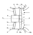
L'invention sera mieux comprise à l'étude de la description d'un mode de réalisation pris à titre nullement limitatif, représenté sur la figure unique. Les flèches représentent le sens d'écoulement du fluide.The invention will be better understood on studying the description of an embodiment taken on a non-limiting basis, represented in the single figure. The arrows represent the direction of flow of the fluid.
Tel qu'il est représenté sur la figure, le ventilateur de l'invention comprend une hélice 1 dont la rotation assure la mise en mouvement du fluide. L'hélice 1 se compose d'une pluralité de pales 2, disposées radialement par rapport à l'axe X-X du ventilateur et d'un moyeu 4 qui supporte les pales 2. Les pales 2 peuvent être de différentes formes suivant la nature du fluide, le débit et la pression voulus. Les pales 2, ici représentées, ont une section transversale trapézoïdale. Les pales 2, sont fixées sur le moyeu 4 par vissage, collage, soudage, sertissage ou tout autre moyen. Elles peuvent également être moulées en une seule matière avec le moyeu 4.As shown in the figure, the fan of the invention comprises a
Le moyeu 4 est fixé sur un arbre 5 qui est entrainé en rotation par un système d'entraînement 6. L'arbre 5 est monté sur des paliers non représentés. Le système d'entraînement 6 est constitué, par exemple, par un moteur électrique, avec ou sans réducteur. Le système d'entraînement 6 est supporté par un certain nombre de montants 7 sensiblement radiaux. Ces montants radiaux 7 sont profilés de manière à réduire les pertes de charge du fluide, lors de l'écoulement. Le nombre de montants 7 peut être de deux, trois ou plus selon les modes de réalisation.The
La tête 7a des montants 7 est en contact avec le boîtier du système d'entraînement 6. Le pied 7b des montants 7 est fixé sur une virole 8 réalisée par exemple en tôle métallique roulée et soudée. Les têtes 7a des montants sont situées en amont des pieds 7b des montants dans le sens d'écoulement du fluide. Dans d'autres modes de réalisation, les têtes 7a des montants 7 peuvent être situées en aval des pieds 7b des montants 7 ou au même niveau.The
La virole 8 qui présente une surface intérieure cylindrique, d'axe X-X est fixée par des moyens de fixation 9 sur un support de ventilateur non représenté. La virole 8 supporte une pièce de raccordement 10 par des brides de fixation 11 situées en aval de l'hélice 1 dans le sens d'écoulement du fluide. La pièce de raccordement 10 comporte une portion cylindrique 10a adjacente à la virole 8 et de même diamètre intérieur. Le diamètre intérieur de la portion cylindrique 10a est légèrement supérieur à celui de l'hélice 1 de façon à laisser un interstice 12 entre l'extrémité des pales 2 de l'hélice 1 et la portion cylindrique 10a. Cet interstice 12 est suffisant pour tenir compte des tolérances de fabrication. La longueur axiale de la portion cylindrique 10a est suffisante pour que la totalité de l'hélice 1 soit logée à l'intérieur de cette portion cylindrique 10a. La pièce de raccordement 10 comporte en outre un pavillon d'aspiration 10b faisant suite sans discontinuité à la portion cylindrique 10a et situé en amont dans le sens d'écoulement du fluide. Le pavillon d'aspiration 10b a la forme d'un tore de manière à assurer le meilleur écoulement possible.The
En fonctionnement, le diamètre de la veine de fluide est réduit par le pavillon d'aspiration 10b au diamètre intérieur de la portion cylindrique 10a afin d'éviter un écoulement tourbillonnaire en amont de l'hélice 1.In operation, the diameter of the fluid stream is reduced by the
Grâce à l'existence de la portion cylindrique 10a, la jonction entre le pavillon 10b et la virole 8 se fait en aval de l'hélice 1 c'est-à-dire à un endroit qui ne risque pas de perturber l'écoulement du fluide lors de l'aspiration par l'hélice 1 et ce, même si cette jonction présente des irrégularités dues à des jeux de fabrication, désaxage ou tolérance des brides de fixation.Thanks to the existence of the
Claims (2)
caractérisé par le fait que la pièce de raccordement (10) présente une portion cylindrique (10a) présentant le même diamètre interne que la virole et munie d'une bride de fixation, ladite portion cylindrique se poursuivant à l'opposé de ladite bride sans discontinuité par la partie (10b) de la pièce de raccordement qui forme le pavillon d'aspiration et ladite portion cylindrique étant de longueur suffisante pour que l'hélice (1) se trouve sensiblement intégralement logée à l'intérieur de ladite partie cylindrique, la zone d'assemblage de la pièce de raccordement avec la virole se trouvant en aval de l'hélice dans le sens d'écoulement du fluide et que le dispositif d'entraînement (6) est supporté à l'intérieur de la virole par au moins deux montants (7) sensiblement radiaux fixés à la virole (8), les têtes (7a) des montants (7) étant situés en amont des pieds (7b) des montants (7) dans le sens d'écoulement du fluide.Helical fan of the type comprising a propeller (1) driven in rotation by a drive device (6) supported inside a cylindrical shell (8), with a connecting piece (10) forming a suction pavilion of general non-developable toric shape assembled at the front end of the ferrule (8) by means of fixing flanges (11),
characterized in that the connecting piece (10) has a cylindrical portion (10a) having the same internal diameter as the ferrule and provided with a fixing flange, said cylindrical portion continuing opposite to said flange without discontinuity by the part (10b) of the connecting piece which forms the suction pavilion and said cylindrical portion being of sufficient length so that the propeller (1) is substantially entirely housed inside said cylindrical part, the area for assembling the connection piece with the ferrule located downstream of the propeller in the direction of flow of the fluid and that the drive device (6) is supported inside the ferrule by at least two substantially radial uprights (7) fixed to the ferrule (8), the heads (7a) of the uprights (7) being located upstream of the feet (7b) of the uprights (7) in the direction of flow of the fluid.
Applications Claiming Priority (2)
| Application Number | Priority Date | Filing Date | Title |
|---|---|---|---|
| FR9412101A FR2725478B1 (en) | 1994-10-11 | 1994-10-11 | HELICOID FAN WITH RUBBER |
| FR9412101 | 1994-10-11 |
Publications (1)
| Publication Number | Publication Date |
|---|---|
| EP0708249A1 true EP0708249A1 (en) | 1996-04-24 |
Family
ID=9467738
Family Applications (1)
| Application Number | Title | Priority Date | Filing Date |
|---|---|---|---|
| EP95402214A Withdrawn EP0708249A1 (en) | 1994-10-11 | 1995-10-04 | Ducted axial fan |
Country Status (2)
| Country | Link |
|---|---|
| EP (1) | EP0708249A1 (en) |
| FR (1) | FR2725478B1 (en) |
Cited By (2)
| Publication number | Priority date | Publication date | Assignee | Title |
|---|---|---|---|---|
| EP3009682A1 (en) * | 2014-10-13 | 2016-04-20 | Thermofin GmbH | Axial fan having outer and inner diffuser |
| US10578126B2 (en) | 2016-04-26 | 2020-03-03 | Acme Engineering And Manufacturing Corp. | Low sound tubeaxial fan |
Citations (7)
| Publication number | Priority date | Publication date | Assignee | Title |
|---|---|---|---|---|
| US2397169A (en) * | 1943-12-06 | 1946-03-26 | Del Conveyor & Mfg Company | Fan and motor structure |
| US2435645A (en) * | 1945-08-23 | 1948-02-10 | Westinghouse Electric Corp | Axial flow fan |
| US2596781A (en) * | 1945-12-29 | 1952-05-13 | Moore Co | Fan |
| CH399643A (en) * | 1962-03-09 | 1965-09-30 | A De Jong N V | Ventilateur axial |
| FR2171666A5 (en) * | 1972-02-04 | 1973-09-21 | Neu Sa | |
| FR2386706A1 (en) * | 1977-04-05 | 1978-11-03 | Neu Ets | Axial flow ventilator fan - has motor mounted by flat radial vanes with leading edges at 45 degrees to fan axis to reduce swirl |
| EP0320926A1 (en) * | 1987-12-17 | 1989-06-21 | Klöckner-Humboldt-Deutz Aktiengesellschaft | Fan |
-
1994
- 1994-10-11 FR FR9412101A patent/FR2725478B1/en not_active Expired - Fee Related
-
1995
- 1995-10-04 EP EP95402214A patent/EP0708249A1/en not_active Withdrawn
Patent Citations (7)
| Publication number | Priority date | Publication date | Assignee | Title |
|---|---|---|---|---|
| US2397169A (en) * | 1943-12-06 | 1946-03-26 | Del Conveyor & Mfg Company | Fan and motor structure |
| US2435645A (en) * | 1945-08-23 | 1948-02-10 | Westinghouse Electric Corp | Axial flow fan |
| US2596781A (en) * | 1945-12-29 | 1952-05-13 | Moore Co | Fan |
| CH399643A (en) * | 1962-03-09 | 1965-09-30 | A De Jong N V | Ventilateur axial |
| FR2171666A5 (en) * | 1972-02-04 | 1973-09-21 | Neu Sa | |
| FR2386706A1 (en) * | 1977-04-05 | 1978-11-03 | Neu Ets | Axial flow ventilator fan - has motor mounted by flat radial vanes with leading edges at 45 degrees to fan axis to reduce swirl |
| EP0320926A1 (en) * | 1987-12-17 | 1989-06-21 | Klöckner-Humboldt-Deutz Aktiengesellschaft | Fan |
Cited By (2)
| Publication number | Priority date | Publication date | Assignee | Title |
|---|---|---|---|---|
| EP3009682A1 (en) * | 2014-10-13 | 2016-04-20 | Thermofin GmbH | Axial fan having outer and inner diffuser |
| US10578126B2 (en) | 2016-04-26 | 2020-03-03 | Acme Engineering And Manufacturing Corp. | Low sound tubeaxial fan |
Also Published As
| Publication number | Publication date |
|---|---|
| FR2725478A1 (en) | 1996-04-12 |
| FR2725478B1 (en) | 1996-12-27 |
Similar Documents
| Publication | Publication Date | Title |
|---|---|---|
| EP1635039B1 (en) | Coupling device with key elements for mounting a seal ring to the stator blades of a gas turbine | |
| EP0498795A1 (en) | Compressor wheel assembly. | |
| CA2763415A1 (en) | Stationary actuator device for controlling the orientation of the blades of a turboprop fan | |
| EP1881179A2 (en) | System for ventilating the wall of a combustion chamber in a turbomachine | |
| EP1672180B1 (en) | Nozzle stage of a distributor actuated by a rotatable ring moved by electric motors | |
| CA2824379C (en) | Fan rotor and associated turbojet engine | |
| WO2009101371A2 (en) | Wheel for hydraulic machine, hydraulic machine including such wheel, and energy conversion plant including such hydraulic machine | |
| FR2732725A1 (en) | FUEL PUMP AND METHOD FOR MANUFACTURING THE SAME | |
| EP0263000B1 (en) | Helicoidal fan with a guiding envelope | |
| FR3093128A1 (en) | Turbomachine housing | |
| WO1999050573A1 (en) | Improved blade wheel | |
| EP1936121B1 (en) | Angular setting of turbomachine stator vanes. | |
| EP1491725B1 (en) | Bearing device for an adjustable vane | |
| EP4185767A1 (en) | Turbine engine module equipped with a propeller and stator vanes supported by retaining means and corresponding turbine engine | |
| EP0708249A1 (en) | Ducted axial fan | |
| EP3473813A1 (en) | Turbine engine with a rectifier unit | |
| FR2990001A1 (en) | Intermediate casing for turbojet, has fixing ring for assembling intermediate casing with thrust reverser casing, where fixing ring includes radial annular leg, and heat exchanger is partly fixed to radial annular leg | |
| FR2887924A1 (en) | Guide for air flow between compressor and combustion chamber of aircraft turbine engine has independent rectifier supported by diffuser | |
| FR2498251A1 (en) | EXHAUST GAS TURBOCHARGER COMPRISING A TURBINE AND A BLOWER COMPRISING TWO FULL SOLIDARIZED WHEELS WITH AUBES | |
| EP1702158B1 (en) | Tip-forming element for hydraulic machine wheel, method of assembling one such wheel, and wheel and hydraulic machine equipped with one such element | |
| EP1936125A1 (en) | Turbomachine compressor | |
| FR2953252A1 (en) | Distribution sector for low pressure turbine of e.g. turbojet of airplane, has outer platform sector comprising stiffeners located in extension of vanes and extended along axis parallel to tangent at upstream and downstream edges of vanes | |
| BE1025131A1 (en) | DOUBLE-CURVED TRANSMISSION SHAFT FOR TURBOMACHINE | |
| FR3068741A1 (en) | DRIVE SHAFT FOR A TURBOMACHINE | |
| FR3081192A1 (en) | IMPROVED FLUID TRANSFER DEVICE FOR SPACE ENGINE |
Legal Events
| Date | Code | Title | Description |
|---|---|---|---|
| PUAI | Public reference made under article 153(3) epc to a published international application that has entered the european phase |
Free format text: ORIGINAL CODE: 0009012 |
|
| AK | Designated contracting states |
Kind code of ref document: A1 Designated state(s): AT CH DE ES IT LI |
|
| 17P | Request for examination filed |
Effective date: 19961017 |
|
| 17Q | First examination report despatched |
Effective date: 19980123 |
|
| STAA | Information on the status of an ep patent application or granted ep patent |
Free format text: STATUS: THE APPLICATION IS DEEMED TO BE WITHDRAWN |
|
| 18D | Application deemed to be withdrawn |
Effective date: 19980603 |