EP0581007A2 - Bearbeitungsraum für Windkanal-Kryomodelle - Google Patents
Bearbeitungsraum für Windkanal-Kryomodelle Download PDFInfo
- Publication number
- EP0581007A2 EP0581007A2 EP93109665A EP93109665A EP0581007A2 EP 0581007 A2 EP0581007 A2 EP 0581007A2 EP 93109665 A EP93109665 A EP 93109665A EP 93109665 A EP93109665 A EP 93109665A EP 0581007 A2 EP0581007 A2 EP 0581007A2
- Authority
- EP
- European Patent Office
- Prior art keywords
- insulating box
- working chamber
- processing room
- model
- cryogenic
- Prior art date
- Legal status (The legal status is an assumption and is not a legal conclusion. Google has not performed a legal analysis and makes no representation as to the accuracy of the status listed.)
- Granted
Links
Images


Classifications
-
- G—PHYSICS
- G01—MEASURING; TESTING
- G01M—TESTING STATIC OR DYNAMIC BALANCE OF MACHINES OR STRUCTURES; TESTING OF STRUCTURES OR APPARATUS, NOT OTHERWISE PROVIDED FOR
- G01M9/00—Aerodynamic testing; Arrangements in or on wind tunnels
- G01M9/02—Wind tunnels
- G01M9/04—Details
Definitions
- the invention relates to a processing room for wind tunnel cryogenic models, in particular for carrying out assembly and other interventions on such models that are to be tested in a cryogenic wind tunnel.
- cryogenic wind tunnels are used, into which the model to be tested is inserted in order to be exposed to a cold gas flow. If such a wind tunnel model is assembled under normal ambient temperature and prepared for the wind tunnel test, it is necessary to cool the model down to the test temperature before inserting it into the wind tunnel. Cooling in the wind tunnel itself would require a very high energy requirement for the cold air to be applied. From "Aeronautical Journal", November 1984, pp. 379 to 394, it is known to bring a cryomodel into a cooling chamber after its preparation for the wind tunnel test and to cool it down to the wind tunnel temperature.
- the model is brought into a quick-change room, in which it is heated, so that a person can manipulate the model can.
- the Quick-change-room forms a treatment chamber that contains an atmosphere that is breathable for people. After the treatment of the model has ended, it is transported into the cooling chamber and cooled down again to wind tunnel conditions. This system requires a separate cooling chamber in addition to the treatment chamber. The energy required to heat and cool the model is very high.
- a wind tunnel system is known from "Cryogenics", vol. 28, January 1988, pp. 10 to 21, which has a model conditioning space under the test area of the wind tunnel. After a test run, the operators move the model and its support from the test area to the conditioning room. A horizontal sliding door separates the conditioning room from the wind tunnel. For model changes, the model is warmed to ambient temperature with warm nitrogen. Before the operators enter the room, dry air is brought into the room. Here too, a large amount of energy is required to heat the model and then cool it.
- the invention has for its object to provide a processing room for wind tunnel cryomodels, with which work can be carried out on cold models and the energy required for keeping the model cold is reduced.
- the processing space for cryogenic models contains an insulating box open at the top for receiving the cryogenic model.
- the model can be inserted into the insulation box from above.
- a low temperature is maintained inside the insulating box by introducing cold air or another cold gas, while the working chamber surrounding the insulating box is supplied with dried hot air.
- the cryo model can be inserted into the isolation chamber from above and kept there under cold conditions.
- the cold air contained in the insulating box remains trapped in the insulating box under the influence of gravity, while the area of the working chamber surrounding the insulating box is kept at a higher temperature level with dried warm air.
- the introduction of dried warm air into the working chamber prevents that condensation forms on the model or in the insulation box.
- the dew point of the supplied warm air is approximately in the range of the cold gas temperature in the isolation chamber.
- a cryogenic model introduced into the insulation box can be cooled down to the wind tunnel temperature in the insulation box or, if it has already been in the wind tunnel, can be kept at the wind tunnel temperature.
- the persons entrusted with carrying out work can stay in the work chamber without having to wear particularly expensive heat protection clothing. You only need gloves and respiratory protection. You can reach into the insulation box with your hands from above and work on the cryo model. People can enter and exit the work chamber through a door without being exposed to significant temperature changes. As a result of the relatively small dimensions of the insulating box, the energy expenditure required to keep the cryomodell cold is low.
- the volume of the working chamber can be viewed as a dry air barrier that separates the cold volume of the insulating box from the moist ambient air outside the working chamber.
- the cold air supply to the insulating box should be such that there is always a very small overflow of cold air over the upper edges of the walls of the insulating box.
- the overflowing cold air mixes immediately with the warm air contained in the working chamber.
- the overflow ensures that no warm air can flow into the insulation box.
- the cold air is in the insulation box due to gravity prevented from rising. It has been found that the stability of the cold air in the insulating box is remarkably good.
- the thermal gradient between the cold gas in the insulation chamber and the ambient air above the insulation chamber is concentrated in an area about 20 cm below the top edge of the insulation box walls. The thermal interaction between cold air in the insulation box and warm air in the working chamber is also very low.
- the insulation box can also be used to cool parts that are to be attached to a cryogenic model to the required temperature and to store them in a cold state.
- the insulating box preferably consists of modular wall elements which are easily detachably connected to one another. In this way, the insulating box can be individually designed according to the shape and size of the cryomodel to be conditioned, so that it has the smallest possible volume.
- Load devices which are located below the floor of the working chamber, are connected with steel cables or steel bars with load frames, which are placed on the different models and are individually adapted.
- Special rope or rod bushings in the walls or in the bottom of the insulation box and the work chamber are adapted accordingly for each model.
- the passages of the steel cables or steel rods can be attached to the disassembled wall elements.
- the temperature in the working chamber can be changed in the range from 300 to 223 K and the temperature in the insulating box in the range from 300 to 100 K.
- the air pressure in the working chamber should be slightly above atmospheric pressure, to prevent atmospheric air from entering the working chamber.
- the overpressure is typically between 50 Pa and 400 Pa.
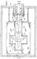
- the processing room for cryomodels contains a working chamber 10 which is airtight against the environment and has a door 11 for the access of persons.
- the working chamber 10 has a movable ceiling door 12 two horizontal wings 12a, 12b, which extend over the entire length of the working chamber and which can be moved apart to open the working chamber upwards.
- the insulating box 13 for receiving the cryomodel 14 to be tested.
- the insulating box 13 is arranged on a frame 15 at a distance above the bottom of the working chamber 10. It has a bottom wall 16 and side walls 17 projecting vertically therefrom.
- the insulating box 13 is open at the top.
- the insulating box 13 extends at one end to a wall 19 of the working chamber 10.
- a channel 21, delimited by walls 20, leads through an opening in this wall 19 into the insulating box 13.
- the channel 21, which is open at the top, receives an elongated holder 24 to which the cryomodell 14 is attached.
- This holder 24 can be fastened to a traveling crane which can move the holder with the cryomodell vertically and move horizontally to a distant location in order to introduce the model into the wind tunnel.
- a door 22 is provided with two wings 22a, 22b which can be swung open on opposite sides, which in the closed state delimits the channel 21 and the end the insulating box 13 closes against the channel.
- the wings 22a and 22b carry adapter blocks 22c, 22d made of insulating material, each with a semicircular cutout.
- the cutouts of the adapter blocks 22c and 22d enclose the holder 24 when it is in a position in which it holds the cryomodel 14 in its position in the insulating box 13. With the door 22 closed, the holder 24 can be rotated about its longitudinal axis in order to also rotate the cryogenic model 14 about its longitudinal axis.
- Additional separately movable caps 23a and 23b are attached to the wings 22a and 22b and close the insulating box 13 against the channel 21 after the holder with the model has been removed. When the wings 22a and 22b are closed and the holder is in position, the caps 23a and 23b are held in the open position by the holder.
- the channel 21 and its door 22 are located in a lock chamber 25, which is part of the insulating box 13 and the walls of which are connected to the wall 19 of the working chamber.
- a lock chamber 25 which is part of the insulating box 13 and the walls of which are connected to the wall 19 of the working chamber.
- the bottom 16a is deeper than the bottom 16 in the remaining area of the insulating box.
- the insulating box 13 consists of modular wall elements 30 which are easily detachably connected to one another and which can be assembled in the manner of a modular system in such a way that the outline of the insulating box 13 can be largely adapted to that of the cryomodel 14.
- the modular wall elements 30 have stepped vertical end edges 31, so that two adjacent wall elements can engage with one another with their end edges, rectangular wall structures being able to be produced.
- Each of the change elements 30 is about 10 cm thick. It has an insulating middle layer made of a material of low thermal mass, which is provided on the outside with a coating of aluminum or stainless steel.
- all metal surfaces of the wall elements and other structures are made of uncoated aluminum or stainless steel. All materials that contain water are provided with water barriers on the outside.
- the wall elements 30 extend to a height of 1.10 m above the work platform 18, so that a person standing on the work platform 18 can intervene in the insulating box 13 from above by hand. Further wall elements 30a with a height of approximately 30 cm can be placed on the wall elements 30 in order to increase the size of the insulating box to 1.40 m.
- the wall elements 30a generally have the same structure as the wall elements 30.
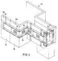
- the walls of the insulating box 13 contain cold air channels 33 (FIG. 3) which run inside the wall elements 30.
- a cold air duct 33 has an inlet 34, to which cold air is supplied.
- outlets 35 made of perforated grids with (not shown) displaceable screens through which the passage cross section can be changed in order to vary the amount of cold air emerging from each outlet 35.
- the cold air is the cold air duct 33 in fed to such a rate that there is just a slight cold air overflow over the upper edge of the insulating box.
- Fig. 5 shows the general structure of the insulating box with the wall elements 30 and 30a. Adjacent wall elements 30 are connected to one another and to the wall elements 30a by angle strips 34 and fastened with screws 35a. The upstanding wall elements 30 are fastened on the floor 16 in such a way that the tightness of the connection is maintained even in the case of thermal changes in length.
- FIG. 5 there is a space 40 under the floor 16 of the insulating box.
- Support structures can optionally be attached to the floor 16 in order to support the model in the insulating box.
- heat-insulating cushions can be provided which are to be fastened on the upper edge of the insulating box 13 are.
Abstract
Description
- Die Erfindung betrifft einen Bearbeitungsraum für Windkanal-Kryomodelle, insbesondere für die Durchführung von Montage- und anderen Eingriffen an derartigen Modellen, die in einem Kryo-Windkanal getestet werden sollen.
- Für aerodynamische Untersuchungen an Flugzeugmodellen o.dgl. im Tieftemperaturbereich werden Kryo-Windkanäle benutzt, in die das zu testende Modell eingebracht wird, um dort einem Kaltgasstrom ausgesetzt zu werden. Wenn ein solches Windkanalmodell unter normaler Umgebungstemperatur montiert und für den Windkanalversuch hergerichtet wird, ist es erforderlich, das Modell vor dem Einbringen in den Windkanal auf die Testtemperatur herunterzukühlen. Eine Kühlung im Windkanal selbst würde einen sehr hohen Energiebedarf für die aufzubringende Kaltluft erfordern. Aus "Aeronautical Journal", November 1984, S. 379 bis 394 ist es bekannt, ein Kryomodell nach seiner Herrichtung für den Windkanalversuch in eine Kühlkammer zu bringen und auf die Windkanaltemperatur herunterzukühlen. Wenn das Modell, nachdem es im Windkanal getestet worden ist, verändert werden muß, um einem weiteren Test unterzogen zu werden, wird das Modell in einen Quick-change-room gebracht, in dem es erwärmt wird, so daß eine Person an dem Modell hantieren kann. Der Quick-change-room bildet eine Behandlungskammer, die eine für Menschen atmungsfähige Atmosphäre enhält. Nach Beendigung der Behandlung des Modells wird dieses in die Kühlkammer transportiert und wieder auf Windkanalverhältnisse heruntergekühlt. Dieses System erfordert außer der Behandlungskammer eine separate Kühlkammer. Der zum Erwärmen und Kühlen des Modells erforderliche Energieaufwand ist sehr hoch.
- Aus "Cryogenics", Vol. 28, Januar 1988, S. 10 bis 21 ist ein Windkanalsystem bekannt, das unter dem Testbereich des Windkanals einen Modell-Konditionierraum aufweist. Nach einem Testlauf bewegen die Operatoren das Modell und seinen Support von dem Testbereich in den Konditionierraum. Eine horizontale Schiebetür trennt den Konditionierraum von dem Windkanal. Für Modelländerungen wird das Modell mit warmem Stickstoff auf Umgebungstemperatur erwärmt. Bevor die Operatoren den Raum betreten, wird trockene Luft in den Raum befördert. Auch hier ist zur Erwärmung des Modells und zur anschließenden Kühlung eine große Energiemenge erforderlich.
- Aus AGARD Report No. 774 "Special Course on Advances in Cryogenic Wind Tunnel Technology", S. 3-1 bis 3-12 ist es bekannt, in den Testbereich des Windtunnels seitlich einen Kanal einzuschieben, der Zugang zu dem im Testbereich befindlichen Modell ermöglicht und von Personen begangen werden kann. Hierzu ist es erforderlich, das Modell und den gesamten Testbereich des Windkanals auf die Umgebungstemperatur zu erwärmen, bevor an dem Modell hantiert werden kann.
- Der Erfindung liegt die Aufgabe zugrunde, einen Bearbeitungsraum für Windkanal-Kryomodelle zu schaffen, mit dem die Durchführung von Arbeiten an kalten Modellen ermöglicht und der für Kalthaltung des Modells erforderliche Energieaufwand verringert wird.
- Die Lösung dieser Aufgabe erfolgt erfindungsgemäß mit den Merkmalen des Patentanspruchs 1.
- Der erfindungsgemäße Bearbeitungsraum für Kryomodelle enthält eine oben offene Isolierbox zur Aufnahme des Kryomodells. Das Modell kann in die Isolierbox von oben her eingeführt werden. Im Innern der Isolierbox wird eine tiefe Temperatur durch Einleiten von Kaltluft oder einem anderen kalten Gas aufrechterhalten, während die die Isolierbox umgebende Arbeitskammer im übrigen mit getrockneter Warmluft versorgt wird. Das Kryomodell kann von oben her in die Isolierkammer eingeführt und dort unter Kältebedingungen gehalten werden. Die in der Isolierbox enthaltene Kaltluft bleibt unter Schwerkrafteinfluß in der Isolierbox gefangen, während der die Isolierbox umgebende Bereich der Arbeitskammer mit getrockneter Warmluft auf einem höheren Temperaturniveau gehalten wird. Durch die Einleitung getrockneter Warmluft in die Arbeitskammer wird verhindert, daß sich an dem Modell oder in der Isolierbox Kondenswasser bildet. Der Taupunkt der zugeführten Warmluft liegt etwa im Bereich der Kaltgastemperatur in der Isolierkammer.
- Ein in die Isolierbox eingebrachtes Kryomodell kann in der Isolierbox auf die Windkanaltemperatur heruntergekühlt werden oder, wenn es bereits im Windkanal gewesen ist, auf Windkanaltemperatur gehalten werden. Die mit der Durchführung von Arbeiten betrauten Personen können sich in der Arbeitskammer aufhalten, ohne eine besonders aufwendige Wärmeschutzkleidung tragen zu müssen. Sie benötigen lediglich Handschuhe und einen Atemschutz. Sie können mit den Händen von oben her in die Isolierbox greifen und an dem Kryomodell hantieren. Die Personen können die Arbeitskammer durch eine Tür betreten und verlassen, ohne dabei erheblichen Temperaturänderungen ausgesetzt zu sein. Infolge der relativ geringen Abmessungen der Isolierbox ist der für die Kalthaltung des Kryomodells erforderliche Energieaufwand gering. Das Volumen der Arbeitskammer kann als Trockenluftsperre betrachtet werden, die das kalte Volumen der Isolierbox von der außerhalb der Arbeitskammer herrschenden feuchten Umgebungsluft trennt. Die in der Arbeitskammer befindlichen Personen sollten Atemmasken tragen, um das Kryomodell gegen Feuchtigkeitsablagerungen zu schützen. Die Kaltluftzufuhr zu der Isolierbox sollte so bemessen sein, daß ständig ein ganz geringer Überlauf an Kaltluft über die Oberkanten der Wände der Isolierbox stattfindet. Die überlaufende Kaltluft vermischt sich sofort mit der in der Arbeitskammer enthaltenen Warmluft. Der Überlauf stellt sicher, daß keine Warmluft in die Isolierbox einfließen kann. In der Isolierbox wird die Kaltluft durch Schwerkrafteinwirkung am Aufsteigen gehindert. Es hat sich herausgestellt, daß die Stabilität der Kaltluft in der Isolierbox bemerkenswert gut ist. Der thermische Gradient zwischen dem Kaltgas in der Isolierkammer und der Umgebungsluft über der Isolierkammer konzentriert sich auf einen Bereich von etwa 20 cm unter der Oberkante der Isolierboxwände. Auch die thermische Wechselwirkung zwischen kalter Luft in der Isolierbox und warmer Luft in Arbeitskammer ist sehr gering.
- Die Isolierbox kann auch dazu benutzt werden, Teile, die an einem Kryomodell befestigt werden sollen, auf die benötigte Temperatur herunterzukühlen und im kalten Zustand zu lagern.
- Vorzugsweise besteht die Isolierbox aus modularen Wandelementen, die leicht lösbar miteinander verbunden sind. Auf diese Weise kann die Isolierbox entsprechend der Form und Größe des zu konditionierenden Kryomodells jeweils individuell gestaltet werden, so daß sie ein möglichst kleines Volumen hat.
- Außerdem wird eine einfache, statische Bealstung der Modelle ermöglicht. Belastungsvorrichtungen, die sich unterhalb des Bodens der Arbeitskammer befinden, werden mit Stahlseilen oder Stahlstangen mit Belastungsrahmen verbunden, die auf die verschiedenen Modelle aufgesetzt werden und individuell angepaßt sind. Spezielle Seil- oder Stangendurchführungen in den Wänden bzw. im Boden der Isolierbox und der Arbeitskammer werden dementsprechend für jedes Modell angepaßt. Die Durchführungen der Stahlseile oder Stahlstangen können an den auseinandergebauten Wandelementen angebracht werden.
- Zur Verdeutlichung der Temperaturbereiche sei angemerkt, daß typischerweise die Temperatur in der Arbeitskammer im Bereich von 300 bis 223 K verändert werden kann und die Temperatur in der Isolierbox im Bereich von 300 bis 100 K. Der Luftdruck in der Arbeitskammer sollte geringfügig über dem Atmosphärendruck liegen, um Eindringen von atmosphärischer Luft in die Arbeitskammer zu vermeiden. Der Überdruck beträgt typischerweise zwischen 50 Pa und 400 Pa.
- Im folgenden wird unter Bezugnahme auf die Zeichnungen ein Ausführungsbeispiel der Erfindung näher erläutert.
- Es zeigen:
- Fig. 1
- eine Draufsicht des Bearbeitungsraumes,
- Fig. 2
- einen Schnitt entlang der Linie II-II von Fig. 1,
- Fig. 3
- eine perspektivische Darstellung eines Teils der Isolierbox zur Erläuterung des Kaltluft-Zuführsystems,
- Fig. 4
- eine perspektivische Gesamtansicht des Bearbeitungsraumes und
- Fig. 5
- eine perspektivische Darstellung des modularen Aufbaus der Isolierbox.
- Der Bearbeitungsraum für Kryomodelle enthält eine gegen die Umgebung luftdicht abschließende Arbeitskammer 10 mit einer Tür 11 für den Zugang von Personen. Die Arbeitskammer 10 weist eine bewegbare Deckentür 12 aus zwei horizontalen Flügeln 12a,12b auf, die sich über die gesamte Länge der Arbeitskammer erstrecken und die auseinanderbewegt werden können, um die Arbeitskammer nach oben zu öffnen.
- In der Arbeitskammer 10 befindet sich die Isolierbox 13 zur Aufnahme des zu testenden Kryomodells 14. Die Isolierbox 13 ist auf einem Gestell 15 mit Abstand über dem Boden der Arbeitskammer 10 angeordnet. Sie weist eine Bodenwand 16 und davon senkrecht aufragende Seitenwände 17 auf. Die Isolierbox 13 ist nach obenhin offen.
- Außerhalb der Isolierbox befindet sich in der Arbeitskammer 10 eine Arbeitsbühne 18 mit Abstand über dem Boden der Arbeitskammer. Kaltluft, die aus der Isolierbox 13 überläuft und die auf den Boden der Arbeitskammer absinkt, gelangt nicht an die Füße der auf der Arbeitsbühne 18 stehenden Personen.
- Die Isolierbox 13 reicht an einem Ende bis an eine Wand 19 der Arbeitskammer 10 heran. Durch eine Öffnung in dieser Wand 19 führt ein von Wänden 20 begrenzter Kanal 21 hindurch in die Isolierbox 13 hinein. Der oben offene Kanal 21 nimmt einen langgestreckten Halter 24 auf, an dem das Kryomodell 14 befestigt wird. Dieser Halter 24 kann an einem Laufkran befestigt sein, der den Halter mit dem Kryomodell vertikal bewegen und horizontal an eine entfernt liegende Stelle verfahren kann, um das Modell in den Windkanal einzuführen. An dem der Isolierbox zugewandten Ende des Kanals 21 ist eine Tür 22 mit zwei nach entgegengesetzten Seiten aufschwenkbaren Flügeln 22a,22b vorgesehen, die im geschlossenen Zustand den Kanal 21 begrenzt und das Ende der Isolierbox 13 gegen den Kanal verschließt. Die Flügel 22a und 22b tragen Adapterblöcke 22c,22d aus Isoliermaterial mit jeweils einem halbkreisförmigen Ausschnitt. Die Ausschnitte der Adapterblöcke 22c und 22d umschließen den Halter 24, wenn dieser sich in einer Position befindet, in der er das Kryomodell 14 in seiner Position in der Isolierbox 13 festhält. Der Halter 24 kann bei geschlossener Tür 22 um seine Längsachse herumgedreht werden, um das Kryomodell 14 ebenfalls um seine Längsachse zu drehen.
- An den Flügeln 22a und 22b sind zusätzliche separat bewegbare Verschlußkappen 23a und 23b angebracht, die die Isolierbox 13 gegen den Kanal 21 verschließen, nachdem der Halter mit dem Modell entfernt wurde. Sind die Flügel 22a und 22b geschlossen und der Halter ist in Position, werden die Verschlußkappen 23a und 23b durch den Halter in geöffneter Position gehalten.
- Der Kanal 21 und seine Tür 22 befinden sich in einer Schleusenkammer 25, die Bestandteil der Isolierbox 13 ist und deren Wände mit der Wand 19 der Arbeitskammer verbunden sind. Im Bereich der Schleusenkammer 25 ist der Boden 16a tiefer als der Boden 16 im übrigen Bereich der Isolierbox.
- Wie insbesondere aus Fig. 1 hervorgeht, besteht die Isolierbox 13 aus modularen Wandelementen 30, die leicht lösbar miteinander verbunden sind und die nach Art eines Baukastensystems derart zusammengesetzt werden können, daß der Grundriß der Isolierbox 13 demjenigen des Kryomodells 14 weitgehend angepaßt werden kann. Die modularen Wandelemente 30 haben abgestufte vertikale Endkanten 31, so daß zwei benachbarte Wandelemente mit ihren Endkanten abdichtend ineinandergreifen können, wobei rechteckige Wandstrukturen erzeugt werden können.
- Jedes der Wandelelemente 30 ist etwa 10 cm stark. Es weist eine isolierende Mittelschicht aus einem Material von geringer thermischer Masse auf, das an seinen Außenseiten mit einer Beschichtung aus Aluminium oder Edelstahl versehen ist.
- Damit die trockene Luft in der Arbeitskammer nicht durch Feuchtigkeit oder sich von den Strukturelementen ablösende Materialien verunreinigt wird, bestehen sämtliche Metalloberflächen der Wandelemente und der sonstigen Strukturen aus unbeschichtetem Aluminium oder Edelstahl. Sämtliche Materialien, die Wasser enthalten, sind an ihren Außenseiten mit Wasserbarrieren versehen.
- Die Wandelemente 30 reichen bis zu einer Höhe von 1,10 m über der Arbeitsbühne 18, so daß eine auf der Arbeitsbühne 18 stehende Person von oben her mit der Hand in die Isolierbox 13 eingreifen kann. Auf die Wandelemente 30 können weitere Wandelemente 30a mit einer Höhe von etwa 30 cm aufgesetzt werden, um die Größe der Isolierbox auf 1,40 m zu vergrößern. Die Wandelemente 30a haben generell die gleiche Struktur wie die Wandelemente 30.
- Die Wände der Isolierbox 13 enthalten Kaltluftkanäle 33 (Fig. 3), die innerhalb der Wandelemente 30 verlaufen. Ein Kaltluftkanal 33 weist einen Einlaß 34 auf, dem Kaltluft zugeführt wird. An den zum Innern der Isolierbox gewandten Seiten des Kaltluftkanals 33 befinden sich Auslässe 35 aus Lochgittern mit (nicht dargestellten) verschiebbaren Blenden, durch die der Durchtrittsquerschnitt verändert werden kann, um die aus jedem Auslaß 35 austretende Kaltluftmenge zu variieren. Die Kaltluft wird dem Kaltluftkanal 33 in einer solchen Rate zugeführt, daß gerade ein geringfügiger Kaltluftüberlauf über den oberen Rand der Isolierbox erfolgt.
- Fig. 5 zeigt den generellen Aufbau der Isolierbox mit den Wandelementen 30 und 30a. Benachbarte Wandelemente 30 sind untereinander und mit den Wandelementen 30a durch Winkelleisten 34 verbunden und mit Schrauben 35a befestigt. Auf dem Boden 16 sind die aufragenden Wandelemente 30 in der Weise befestigt, daß die Dichtheit des Anschlusses auch bei thermischen Längenänderungen aufrecht erhalten bleibt.
- Wie ferner aus Fig. 5 ersichtlich ist, ist unter dem Boden 16 der Isolierbox ein den Zugang ermöglichender Raum 40 vorhanden. Auf dem Boden 16 können ggf. Stützstrukturen angebracht sein, um das Modell in der Isolierbox abzustützen.
- Um zu vermeiden, daß eine auf der Arbeitsbühne stehende Person, die mit den Händen in das Innere der Isolierbox greift, mit der Oberkante der Wand der Isolierbox in Berührung kommt, können wärmeisolierende Kissen vorgesehen sein, die auf dem oberen Rand der Isolierbox 13 zu befestigen sind.
Claims (9)
- Bearbeitungsraum für ein Windkanal-Kryomodell, mit einer verschließbaren, mit getrockneter Luft beheizbaren Arbeitskammer (10), die eine oben offene Isolierbox (13) aus wärmeisolierendem Material enthält, in welche Kaltgas einleitbar ist.
- Bearbeitungsraum nach Anspruch 1, dadurch gekennzeichnet, daß eine der die Isolierbox begrenzenden Wände (19) eine Tür (22) enthält, die derart ausgebildet ist, daß sie im geschlossenen Zustand einen das Kryomodell (14) tragenden Halter (24) durchläßt.
- Bearbeitungsraum nach Anspruch 1 oder 2, dadurch gekennzeichnet, daß die Isolierbox (13) auf einem Gestell (15) mit Abstand über dem Boden der Arbeitskammer (10) ruht.
- Bearbeitungsraum nach einem der Ansprüche 1 bis 3, dadurch gekennzeichnet, daß außerhalb der Isolierbox (13) eine Arbeitsbühne (18) mit Abstand über dem Boden der Arbeitskammer (10) vorgesehen ist.
- Bearbeitungsraum nach einem der Ansprüche 1 bis 4, dadurch gekennzeichnet, daß die Arbeitskammer (10) über der Isolierbox (13) mindestens eine bewegbare Deckentür (12) aufweist, die das Herausheben des das Kryomodell (14) tragenden Halters (24) aus der Arbeitskammer (10) ermöglicht.
- Bearbeitungsraum nach einem der Ansprüche 1 bis 5, dadurch gekennzeichnet, daß die Wände der Isolierbox (13) Kaltgaskanäle (33) mit in die Isolierbox hineinführenden Auslässen (35) enthalten.
- Bearbeitungsraum nach einem der Ansprüche 1 bis 6, dadurch gekennzeichnet, daß die Isolierbox (13) aus bausteinartig kombinierbaren Wandelementen (30) besteht, die leicht lösbar zu unterschiedlichen Geometrien der Isolierbox (13) zusammensetzbar sind.
- Bearbeitungsraum nach einem der Ansprüche 1 bis 7, dadurch gekennzeichnet, daß auf die Wände der Isolierbox (13) aufsetzbare Wandelemente (30a) vorgesehen sind, um die Wandhöhe zu vergrößern.
- Bearbeitungsraum nach einem der Ansprüche 1 bis 8, dadurch gekennzeichnet, daß wärmeisolierende Kissen vorgesehen sind, die auf dem oberen Rand der Isolierbox (13) zu befestigen sind.
Applications Claiming Priority (2)
| Application Number | Priority Date | Filing Date | Title |
|---|---|---|---|
| DE4225152A DE4225152A1 (de) | 1992-07-30 | 1992-07-30 | Bearbeitungsraum für Windkanal-Kryomodelle |
| DE4225152 | 1992-07-30 |
Publications (3)
| Publication Number | Publication Date |
|---|---|
| EP0581007A2 true EP0581007A2 (de) | 1994-02-02 |
| EP0581007A3 EP0581007A3 (de) | 1994-02-16 |
| EP0581007B1 EP0581007B1 (de) | 1996-12-18 |
Family
ID=6464436
Family Applications (1)
| Application Number | Title | Priority Date | Filing Date |
|---|---|---|---|
| EP93109665A Expired - Lifetime EP0581007B1 (de) | 1992-07-30 | 1993-06-17 | Bearbeitungsraum für Windkanal-Kryomodelle |
Country Status (5)
| Country | Link |
|---|---|
| US (1) | US5365782A (de) |
| EP (1) | EP0581007B1 (de) |
| JP (1) | JPH06102137A (de) |
| AT (1) | ATE146590T1 (de) |
| DE (2) | DE4225152A1 (de) |
Cited By (1)
| Publication number | Priority date | Publication date | Assignee | Title |
|---|---|---|---|---|
| CN112197933A (zh) * | 2020-12-10 | 2021-01-08 | 中国空气动力研究与发展中心低速空气动力研究所 | 可调宽度的开口射流风洞驻室及开口射流风洞试验方法 |
Families Citing this family (11)
| Publication number | Priority date | Publication date | Assignee | Title |
|---|---|---|---|---|
| US5627312A (en) * | 1995-12-22 | 1997-05-06 | The Boeing Company | Variable resistance ventilated adaptive wind tunnel walls |
| DE29614036U1 (de) * | 1996-08-13 | 1997-12-11 | Meyer Thomas J | Lärmschutzhalle für Flugzeuge |
| DE10208258B4 (de) * | 2002-02-26 | 2004-05-06 | Deutsches Zentrum für Luft- und Raumfahrt e.V. | Vorrichtung zur Bereitstellung eines veränderlichen Strömungsprofils, inbesondere bei einem in einer kryogenen Umgebung angeordneten Strömungskörper |
| US9134195B1 (en) * | 2013-01-03 | 2015-09-15 | The Boeing Company | Methods and systems for enabling wind tunnel models to transition between measuring aerodynamic forces and measuring acoustic signatures |
| US9045232B1 (en) | 2013-03-14 | 2015-06-02 | Timothy A. Burke | Transportable system for simulating free fall in air |
| RU2629696C1 (ru) * | 2016-10-21 | 2017-08-31 | Федеральное государственное бюджетное учреждение науки Институт машиноведения им. А.А. Благонравова Российской академии наук (ИМАШ РАН) | Устройство для изменения положения модели в рабочей части аэродинамической трубы |
| RU2660225C1 (ru) * | 2017-10-05 | 2018-07-05 | Федеральное государственное унитарное предприятие "Центральный аэрогидродинамический институт имени профессора Н.Е. Жуковского" (ФГУП "ЦАГИ") | Способ управления положением модели в аэродинамической трубе |
| CN108414182B (zh) * | 2018-04-23 | 2023-11-10 | 中国空气动力研究与发展中心低速空气动力研究所 | 一种翼型横摆振荡风洞试验装置 |
| RU2708680C1 (ru) * | 2019-04-22 | 2019-12-11 | Акционерное общество "Центральный научно-исследовательский институт машиностроения" (АО "ЦНИИмаш") | Устройство для изменения положения модели в рабочей части аэродинамической трубы |
| RU2708681C1 (ru) * | 2019-04-22 | 2019-12-11 | Акционерное общество "Центральный научно-исследовательский институт машиностроения" (АО "ЦНИИмаш") | Устройство для изменения положения модели в рабочей части аэродинамической трубы |
| CN112595483B (zh) * | 2020-12-08 | 2022-09-20 | 中国空气动力研究与发展中心设备设计及测试技术研究所 | 一种热结构风洞速度型流场调节装置 |
Citations (1)
| Publication number | Priority date | Publication date | Assignee | Title |
|---|---|---|---|---|
| EP0379822A1 (de) * | 1988-12-29 | 1990-08-01 | Societe Nouvelle Technigaz | Thermisch isolierende Abdichtung der Innenwand eines Trockenraumes |
Family Cites Families (4)
| Publication number | Priority date | Publication date | Assignee | Title |
|---|---|---|---|---|
| US3492767A (en) * | 1968-02-19 | 1970-02-03 | Core Properties Dev Corp | Prefabricated building construction |
| US5054295A (en) * | 1990-08-21 | 1991-10-08 | Goulooze Gene D | Transport with variable volume, independently cooled compartments |
| US5119935A (en) * | 1991-01-29 | 1992-06-09 | Grumman Aerospace Corporation | VTOL aircraft convertible shipping container and method of use |
| US5168675A (en) * | 1991-05-20 | 1992-12-08 | Fairmont Homes, Inc. | Pool for manufactured structure |
-
1992
- 1992-07-30 DE DE4225152A patent/DE4225152A1/de not_active Withdrawn
-
1993
- 1993-06-17 AT AT93109665T patent/ATE146590T1/de active
- 1993-06-17 EP EP93109665A patent/EP0581007B1/de not_active Expired - Lifetime
- 1993-06-17 DE DE59304792T patent/DE59304792D1/de not_active Expired - Fee Related
- 1993-07-22 US US08/096,616 patent/US5365782A/en not_active Expired - Fee Related
- 1993-07-30 JP JP5206948A patent/JPH06102137A/ja active Pending
Patent Citations (1)
| Publication number | Priority date | Publication date | Assignee | Title |
|---|---|---|---|---|
| EP0379822A1 (de) * | 1988-12-29 | 1990-08-01 | Societe Nouvelle Technigaz | Thermisch isolierende Abdichtung der Innenwand eines Trockenraumes |
Non-Patent Citations (1)
| Title |
|---|
| CRYOGENICS Bd. 28 , Januar 1988 Seiten 10 - 21 D.A. DRESS, E.A. 'CRYOGENIC WIND TUNNEL RESEARCH: A GLOBAL PERSPECTIVE' * |
Cited By (1)
| Publication number | Priority date | Publication date | Assignee | Title |
|---|---|---|---|---|
| CN112197933A (zh) * | 2020-12-10 | 2021-01-08 | 中国空气动力研究与发展中心低速空气动力研究所 | 可调宽度的开口射流风洞驻室及开口射流风洞试验方法 |
Also Published As
| Publication number | Publication date |
|---|---|
| DE4225152A1 (de) | 1994-02-03 |
| EP0581007B1 (de) | 1996-12-18 |
| DE59304792D1 (de) | 1997-01-30 |
| US5365782A (en) | 1994-11-22 |
| ATE146590T1 (de) | 1997-01-15 |
| JPH06102137A (ja) | 1994-04-15 |
| EP0581007A3 (de) | 1994-02-16 |
Similar Documents
| Publication | Publication Date | Title |
|---|---|---|
| EP0581007B1 (de) | Bearbeitungsraum für Windkanal-Kryomodelle | |
| EP1673609A2 (de) | Vorrichtung und verfahren zur handhabung einer kryoprobe | |
| DE3133936A1 (de) | Brutschrank | |
| DE112010005583T5 (de) | Datenzentrumskühlung | |
| DE69828195T2 (de) | Arbeitseinrichtung mit niedriger luftfeuchtigkeit | |
| DE10303736B4 (de) | Klimaschrank und insbesondere Klimakühlschrank | |
| DE3441091C2 (de) | ||
| DE3533271C2 (de) | ||
| DE3516505C1 (de) | Holzbehandlungskammer | |
| DE4210807A1 (de) | Luftdurchlaß | |
| DE1961056C3 (de) | Frischluftdurchströmte Saunakabine | |
| EP0948688A1 (de) | An ein baugerüst anbringbare witterungsschutzeinrichtung | |
| DE2206799B2 (de) | Belüftungseinrichtung für Viehställe | |
| DE1082015B (de) | Kuehlofen fuer Glas | |
| DE677920C (de) | Verfahren und Vorrichtung zum Haerten von Gegenstaenden aus Glas | |
| DE2852815C2 (de) | ||
| DE2163690A1 (de) | Sauna-entlueftungsvorrichtung | |
| DE4136247A1 (de) | Vorrichtung zum verteilen von luft oder loeschgasen | |
| DE2021121A1 (de) | Klimatisierbare Kabine mit Vollsicht | |
| DE954604C (de) | Verfahren und Vorrichtung zur Kuehlraumtemperaturregelung | |
| DE3318635C2 (de) | Kühlzelle für die Lagerung von Backwaren und Teiglingen | |
| DE922715C (de) | Einrichtung zur Waermebehandlung von Gasen, insbesondere Luft | |
| EP0558917A1 (de) | Filtervorrichtung mit Gehäuse und in dem Gehäuse befindlichen Filterelementen | |
| DE2627727B2 (de) | Fenster mit zwei im Abstand hintereinander angeordneten Rahmen | |
| EP0632986B1 (de) | Kühlvorrichtung für die Lagerung von Gebäck |
Legal Events
| Date | Code | Title | Description |
|---|---|---|---|
| PUAI | Public reference made under article 153(3) epc to a published international application that has entered the european phase |
Free format text: ORIGINAL CODE: 0009012 |
|
| PUAL | Search report despatched |
Free format text: ORIGINAL CODE: 0009013 |
|
| AK | Designated contracting states |
Kind code of ref document: A2 Designated state(s): AT BE CH DE DK FR GB GR IT LI NL PT SE |
|
| AK | Designated contracting states |
Kind code of ref document: A3 Designated state(s): AT BE CH DE DK FR GB GR IT LI NL PT SE |
|
| 17P | Request for examination filed |
Effective date: 19940604 |
|
| GRAG | Despatch of communication of intention to grant |
Free format text: ORIGINAL CODE: EPIDOS AGRA |
|
| 17Q | First examination report despatched |
Effective date: 19960215 |
|
| GRAH | Despatch of communication of intention to grant a patent |
Free format text: ORIGINAL CODE: EPIDOS IGRA |
|
| GRAH | Despatch of communication of intention to grant a patent |
Free format text: ORIGINAL CODE: EPIDOS IGRA |
|
| GRAA | (expected) grant |
Free format text: ORIGINAL CODE: 0009210 |
|
| AK | Designated contracting states |
Kind code of ref document: B1 Designated state(s): AT BE CH DE DK FR GB GR IT LI NL PT SE |
|
| PG25 | Lapsed in a contracting state [announced via postgrant information from national office to epo] |
Ref country code: NL Free format text: LAPSE BECAUSE OF FAILURE TO SUBMIT A TRANSLATION OF THE DESCRIPTION OR TO PAY THE FEE WITHIN THE PRESCRIBED TIME-LIMIT Effective date: 19961218 Ref country code: GR Free format text: LAPSE BECAUSE OF FAILURE TO SUBMIT A TRANSLATION OF THE DESCRIPTION OR TO PAY THE FEE WITHIN THE PRESCRIBED TIME-LIMIT Effective date: 19961218 Ref country code: DK Effective date: 19961218 |
|
| REF | Corresponds to: |
Ref document number: 146590 Country of ref document: AT Date of ref document: 19970115 Kind code of ref document: T |
|
| ITF | It: translation for a ep patent filed |
Owner name: ING. A. GIAMBROCONO & C. S.R.L. |
|
| GBT | Gb: translation of ep patent filed (gb section 77(6)(a)/1977) |
Effective date: 19961231 |
|
| REF | Corresponds to: |
Ref document number: 59304792 Country of ref document: DE Date of ref document: 19970130 |
|
| ET | Fr: translation filed | ||
| PG25 | Lapsed in a contracting state [announced via postgrant information from national office to epo] |
Ref country code: PT Effective date: 19970318 |
|
| NLV1 | Nl: lapsed or annulled due to failure to fulfill the requirements of art. 29p and 29m of the patents act | ||
| PG25 | Lapsed in a contracting state [announced via postgrant information from national office to epo] |
Ref country code: AT Free format text: LAPSE BECAUSE OF NON-PAYMENT OF DUE FEES Effective date: 19970617 |
|
| PG25 | Lapsed in a contracting state [announced via postgrant information from national office to epo] |
Ref country code: LI Free format text: LAPSE BECAUSE OF NON-PAYMENT OF DUE FEES Effective date: 19970630 Ref country code: CH Free format text: LAPSE BECAUSE OF NON-PAYMENT OF DUE FEES Effective date: 19970630 Ref country code: BE Effective date: 19970630 |
|
| PLBE | No opposition filed within time limit |
Free format text: ORIGINAL CODE: 0009261 |
|
| STAA | Information on the status of an ep patent application or granted ep patent |
Free format text: STATUS: NO OPPOSITION FILED WITHIN TIME LIMIT |
|
| 26N | No opposition filed | ||
| BERE | Be: lapsed |
Owner name: EUROPEAN TRANSONIC WINDTUNNEL G.M.B.H. Effective date: 19970630 |
|
| REG | Reference to a national code |
Ref country code: CH Ref legal event code: PL |
|
| PGFP | Annual fee paid to national office [announced via postgrant information from national office to epo] |
Ref country code: FR Payment date: 19980518 Year of fee payment: 6 |
|
| PGFP | Annual fee paid to national office [announced via postgrant information from national office to epo] |
Ref country code: GB Payment date: 19980527 Year of fee payment: 6 |
|
| PGFP | Annual fee paid to national office [announced via postgrant information from national office to epo] |
Ref country code: SE Payment date: 19980623 Year of fee payment: 6 |
|
| PGFP | Annual fee paid to national office [announced via postgrant information from national office to epo] |
Ref country code: DE Payment date: 19980805 Year of fee payment: 6 |
|
| PG25 | Lapsed in a contracting state [announced via postgrant information from national office to epo] |
Ref country code: GB Free format text: LAPSE BECAUSE OF NON-PAYMENT OF DUE FEES Effective date: 19990617 |
|
| PG25 | Lapsed in a contracting state [announced via postgrant information from national office to epo] |
Ref country code: SE Free format text: THE PATENT HAS BEEN ANNULLED BY A DECISION OF A NATIONAL AUTHORITY Effective date: 19990629 |
|
| PG25 | Lapsed in a contracting state [announced via postgrant information from national office to epo] |
Ref country code: FR Free format text: THE PATENT HAS BEEN ANNULLED BY A DECISION OF A NATIONAL AUTHORITY Effective date: 19990630 |
|
| GBPC | Gb: european patent ceased through non-payment of renewal fee |
Effective date: 19990617 |
|
| EUG | Se: european patent has lapsed |
Ref document number: 93109665.5 |
|
| PG25 | Lapsed in a contracting state [announced via postgrant information from national office to epo] |
Ref country code: DE Free format text: LAPSE BECAUSE OF NON-PAYMENT OF DUE FEES Effective date: 20000503 |
|
| REG | Reference to a national code |
Ref country code: FR Ref legal event code: ST |
|
| PG25 | Lapsed in a contracting state [announced via postgrant information from national office to epo] |
Ref country code: IT Free format text: LAPSE BECAUSE OF NON-PAYMENT OF DUE FEES Effective date: 20050617 |