EP0516927A2 - Barcode system - Google Patents
Barcode system Download PDFInfo
- Publication number
- EP0516927A2 EP0516927A2 EP92104632A EP92104632A EP0516927A2 EP 0516927 A2 EP0516927 A2 EP 0516927A2 EP 92104632 A EP92104632 A EP 92104632A EP 92104632 A EP92104632 A EP 92104632A EP 0516927 A2 EP0516927 A2 EP 0516927A2
- Authority
- EP
- European Patent Office
- Prior art keywords
- bar code
- code system
- scanning beam
- beam generating
- generating device
- Prior art date
- Legal status (The legal status is an assumption and is not a legal conclusion. Google has not performed a legal analysis and makes no representation as to the accuracy of the status listed.)
- Granted
Links
Images


Classifications
-
- G—PHYSICS
- G06—COMPUTING; CALCULATING OR COUNTING
- G06K—GRAPHICAL DATA READING; PRESENTATION OF DATA; RECORD CARRIERS; HANDLING RECORD CARRIERS
- G06K7/00—Methods or arrangements for sensing record carriers, e.g. for reading patterns
- G06K7/10—Methods or arrangements for sensing record carriers, e.g. for reading patterns by electromagnetic radiation, e.g. optical sensing; by corpuscular radiation
- G06K7/12—Methods or arrangements for sensing record carriers, e.g. for reading patterns by electromagnetic radiation, e.g. optical sensing; by corpuscular radiation using a selected wavelength, e.g. to sense red marks and ignore blue marks
Definitions
- the invention relates to a bar code system with bar codes located on a background and with a bar code reading device which has a scanning beam generating device and reading means for reading the respective bar code, the information content of which is formed by bars and / or gaps of different widths.
- Bar code reading systems or reading devices are known in different designs.
- US Pat. No. 4,093,865 discloses a stationary bar code reading system.
- Manually portable bar code reading systems are also commercially available.
- the known bar code reading devices have in common that they can read bar codes attached to goods or the like.
- a scanning beam is guided by a scanning beam generating device over the bar code and the scanning result is picked up by reading means which carry out an evaluation.
- the bar codes used in practice consist of a series of parallel ones arranged side by side Strokes of constant or different widths and gaps between them also constant or different widths.
- the wavelength of the scanning beam is generally in the visible spectral range; however, it is also entirely possible to choose a wavelength that is in the infrared range.
- bar codes are read which are represented by black lines on a white background in the classic sense.
- color combinations defined by the EAN system which can be detected on the basis of red light or infrared reading devices. Other color combinations cannot be detected with the known reading devices.
- the invention is therefore based on the object of providing a bar code reading device of the type mentioned at the outset which can detect bar codes with a special bar color or with special bar colors on a selectable background color or selectable background colors.
- Multicolored are also preferred Bar codes, in particular multicolored bar colors and / or multicolored background colors, legible.
- the scanning beam generating device emits radiation of different wavelengths at the same time or in succession in order to recognize the color-selectable lines or gaps on the color-selectable background.
- the wavelength of the scanning beams is matched to the color combination of bar color or bar colors of the bar code and background color or background color.
- the bar code is integrated into the product in a quasi-color manner and remains legible due to the invention. Moreover, because of the configuration according to the invention, it is no longer necessary to use a further printing color (for example black) for the bar code, since the color of the other printing can also be used for the bar code. This represents a significant cost saving in the area of the packaging sector. It should also be pointed out that the code information is provided by the widths of the code bars or gaps between the bars, but not by the color of the code.
- the scanning beam generating device may have a plurality of sources of different wavelengths which emit radiation cyclically in succession.
- the scanning beam generating device has only one source, which is, however, able to transmit different wavelengths cyclically one after the other. It is then a so-called “tunable source”.
- a source is always to be understood as a light source, the light of which can be in the visible as well as in the infrared range.
- the scanning beam generating device has a deflection device for guiding the beams of the transmitted scanning beams. This deflection device oscillates so that the scanning beams sweep over a reading area.
- the bar code reading device has a receiver which belongs to the reading means and serves the reading process of the radiation reflected by the bar code and the background.
- the deflection device can preferably be designed as an oscillating deflection mirror.
- the mirror is provided with a corresponding drive for the oscillation movement.
- a mirrored, rotating polygon roller as the deflection device.
- the individual flat lateral surfaces of this polygon roller when rotated, effect a corresponding beam guidance of the scanning beams, so that a certain reading area in which the bar code is located is detected.
- a sensor is arranged in the beam path, which detects the oscillation interval of the deflection device and changes the wavelength of the scanning beam generating device after at least one oscillation interval.
- a scanning beam with a changing wavelength is continuously emitted after the expiry of one or a preselectable number of oscillation intervals.
- different scanning beam generating devices each with an associated wavelength, can be activated in succession, or their frequency and thus the wavelength of the scanning beam emitted by the same scanning beam generating device are changed.
- it is a so-called tunable source, in which a new tuning to a different wavelength takes place after each or several preselectable oscillation intervals.
- the scanning beam generating device can be designed as a laser arrangement.
- the scanning beam generating device is connected to at least one optical waveguide (LWL) with which the radiation of different wavelengths is guided into the immediate vicinity of the bar code.
- This optical fiber is an outgoing conductor, the means that it transports the scanning radiation to the bar code.
- the radiation reflected by the bar code is fed to the receiver by means of at least one further optical waveguide.
- This further optical waveguide thus serves as a return conductor.
- Forward and return conductors can be formed in particular by fiber optic cables.
- a deflection device for example a rotating deflection mirror
- the radiation is sent via the optical waveguide in the immediate vicinity of the bar code, hits the bar code there and is reflected accordingly and is detected by the optical waveguide serving as a return conductor and fed to the receiver.
- This arrangement naturally presupposes that the bar code-side ends of the optical waveguides (forward and return conductors) and the bar code perform a relative movement to one another, so that all bars or gaps in the bar code can be detected. This can be done by moving the optical fiber relative to the bar code or the bar code relative to the optical fibers. A combinatorial movement is also conceivable, that is to say both the optical waveguide and the bar code move.
- the scanning beam generating device is a white light source coupled to the optical waveguide (outgoing conductor).
- optical waveguides which serve as outgoing conductors and which are coupled to radiation sources having mutually different wavelengths, each of these optical waveguides being assigned to one of the radiation sources of the scanning beam generating device.
- the radiation sources can be light-emitting diodes of different colors or lasers of different colors.
- the optical waveguides assigned to one another and serving as outgoing and return conductors are combined as a pair of optical waveguides running spatially close to one another.
- This spatially dense combination certainly only needs in the area of the bar code-side ends of the optical waveguide of the associated Optical fiber pair apply, since it is then ensured that the radiation supplied by the outgoing conductor and reflected by the bar code is reliably readable by the return conductor.
- the individual pairs of optical fibers can be combined as a bundle.
- the individual pairs of optical fibers are arranged distributed over the detection area of the bar code.
- An amplifier is preferably connected to the receiver end of each optical waveguide serving as a return conductor, so that the received signals can be amplified.
- the optical waveguides serving as return conductors can lead to a logic logic circuit with which the received signals (reflected radiation) or else the received signals amplified by the amplifiers can be logically linked, in particular "logically and" and / or "logically or”.
- the output of this logic logic circuit is connected to a decoder, which evaluates the pulse train received.
- the ends of the optical waveguide on the bar code side are assigned a transmitting / reading optical system.
- FIG. 1 shows a schematic representation of a bar code reading device 1 which is used to detect a bar code 2 which is located on a background 3.
- the lines 4 indicate the limits of the reading range of the bar code reading device 1.
- a plurality of scanning beam generating devices 6, 6 'etc. are accommodated, which throw the radiation generated by them onto a deflection device 7, which deflect the scanning beams and fan them out across the width of the detection area / reading area.
- a deflection device 7 which deflect the scanning beams and fan them out across the width of the detection area / reading area.
- FIG 1 only two scanning beam generating devices 6 and 6 'are shown. However, the invention is not limited to this; further scanning beam generating devices can be provided.
- Each scanning beam generating device 6 or 6 'etc. differs from another scanning beam generating device by the wavelength of the emitted scanning beams, so that the bar code 2 is simultaneously or successively exposed to a plurality of different wavelengths of scanning beams.
- the deflection device 7 has a deflection mirror 8 which is provided with a drive 9 for an oscillatory movement. Due to the oscillating movement of the deflection mirror 8, each scanning beam is fanned out in accordance with the reading area delimited by the lines 4.
- the fan beams preferably pass through an optical system 10.
- the radiation reflected by the bar code 2 and the background 3 is detected by a receiver 11, which feeds the received signal to a decoder 13 via a pulse shaper stage 12.
- An interface 14, which leads to an evaluation unit 15, is connected to the output of the decoder 13.
- the evaluation unit 15 analyzes the information content of the bar code 2.
- the individual scanning beam generating devices 6, 6 'etc. each emit a different wavelength, it is possible to detect corresponding bar code colors and / or background colors, so that codes with corresponding colors and / or codes of different colors are available due to the large number of available wavelengths are detectable.
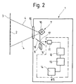
- FIG. 2 shows a further embodiment, which largely corresponds to the embodiment of FIG. 2. Only the differences from the exemplary embodiment in FIG. 1 will be discussed here. These differences are that instead of the oscillating deflecting mirror 8, a mirrored, rotating polygon roller 16 is provided. Furthermore, the bundled scanning beams coming from the scanning beam generating devices 6, 6 'etc. pass through openings 17 of a mirror 18 which is arranged between the individual scanning beam generating devices 6, 6' and the polygon roller 16. It serves the reflected radiation coming from the polygon roller 16 to redirect them to the receiver 11.
- FIG. 3 shows a further exemplary embodiment, which differs from that of FIG. 1 in that only one scanning beam generating device 6 is provided, which is controlled by a sensor 19.
- the sensor 19 registers the oscillation interval of the deflection device 7 and, after one or a predeterminable number of oscillation intervals, causes the wavelength of the emitted radiation of the scanning beam generating device 6 to change.
- This exemplary embodiment is therefore a tunable source, that is to say that the wavelength of the emitted radiation can be changed stepwise or continuously by appropriate control. In this respect, it is possible to detect corresponding bar code colors or background colors of bar code 2.
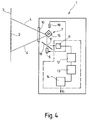
- FIG. 4 shows a last exemplary embodiment of a barcode reading device according to the invention, which differs from the exemplary embodiment in FIG. 2 in that it also has a sensor 19 in order to control the tunable scanning beam generating device 6 in the rhythm of the oscillation interval to emit different wavelengths can.
- the lines have a greater degree of absorption of the radiation compared to the gaps.
- an inverse code display is also conceivable, in which the lines have a lower absorption capacity than the gaps.
- both variants are suitable for capturing the bar code.
- the bar code reading device can be designed as a compact device or else as a plurality of separate structural units which are connected to one another by cables. It can be designed as a stationary arrangement or else as a manually portable arrangement. In the latter case, it is possible to provide a manually portable reading head, which may also contain the evaluation circuit and which can be connected to a stationary unit via an electrical cable.
- a receiver In the case of a tunable scanning beam generating device, a receiver is used which, on the one hand, has the spectral sensitivity of the variation of the tunable transmitter or, on the other hand, enables the switching of a receiving element in connection with the synchronization of the tuning to the respective sensitivity (wavelength).
- the scanning beam generating device with its deflection unit can also be used according to the invention trained omni-directional scanner.
- Figure 5 shows schematically a reading method of a bar code 2, which works on the principle of "ladder arrangement" (ladder).
- the bar code reading device for example designed according to the exemplary embodiment in FIG. 1, guides the scanning beam 20 transversely to the bar profile of the bar code 2, the object 21 carrying the bar code 2 moving in the direction of the longitudinal extent of the bars of the bar code 2.
- FIG. 6 illustrates another principle that is referred to as a "picket fence". While the beam guidance in the embodiment of FIG. 5 takes place transversely to the direction of movement of the object 21, in the embodiment of FIG. 6- the direction of movement of the scanning beam 20 coincides with the movement of the object 21. The direction of movement of the object 21 is indicated by an arrow 22.
- the scanning corresponds approximately to that in the exemplary embodiment in FIG. 6, but a special bar code reading device 1 is used which does not fan out the scanning beam by means of a steering device, so that a corresponding area delimited by the lines 4 is cyclically swept , but an optical waveguide 23 is provided which receives the radiation originating from a white light radiation source up to the immediate vicinity of the bar code 2 leads.
- the radiation of different wavelengths emerges from the end 24 of the optical waveguide 23 on the bar code side and strikes the bar code 2.
- the reflected radiation reaches another optical waveguide 25 and is fed by the latter to the scanning beam receiving device 1 for reading.
- the optical waveguide 23 serves as an outgoing conductor and the optical waveguide 25 as a return conductor.
- the condition for reading the bar code 2 is that there is a relative movement between the end 24 and the end 26 of the optical fibers 23 and 25 relative to the bar code 2, so that all lines and gaps in the code can be detected. According to the exemplary embodiment in FIG. 7, this is given by the fact that the object 21 carrying the bar code 2 travels under the ends 24 and 26 of the optical waveguides 23 and 25. According to another embodiment, not shown, it is also conceivable that the optical fiber ends 24 and 26 are moved relative to the bar code 2 over this.
- FIGS. 8 and 9 show configurations of the exemplary embodiment in FIG. 7. It can be seen that a white light radiation source 27 guides radiation of different wavelengths to the object 21 carrying the bar code 2 via the optical waveguide 23.
- the optical waveguide 23 forms an outgoing conductor, which with the return conductor (Optical fiber 25) is combined to form a pair of optical fibers 28 running closely next to each other.
- a transmission / reading optic 29 is arranged, which is used for beam bundling and thus the optimal transmission and reading behavior.
- This transmission / reading optics 29 can be designed jointly or separately for the two optical fibers 23 and 25.
- the radiation reflected by the object 21 is fed via the optical waveguide 25 to an optical receiving system 30 (receiver 11) which preferably has one or more radiation-sensitive photodiodes or the like.
- the receiving optics 30 is connected to an amplifier 31, which amplifies the received signal and feeds it to a decoder 32, which carries out the evaluation of the bar code information.
- the exemplary embodiment in FIG. 9 shows a structure similar to that which is already known from FIG. 8, but not a single white light radiation source is provided, but rather a plurality of radiation sources 33 - of which three are shown by way of example in FIG. 9 - the radiation emit different wavelength.
- the radiation sources 33 can be light-emitting diodes of different colors or lasers of different colors.
- the radiation is supplied to the object 21 carrying the bar code 2 via corresponding optical waveguides 23 assigned to each radiation source 33.
- everyone as a leader serving optical waveguide 23 is assigned an optical waveguide 25 serving as a return conductor, an outgoing conductor and a return conductor each forming a pair of optical waveguides 28.
- the individual optical fiber pairs 28 are combined as a bundle 34, which has a transmitting / reading optic 29 at its bar code-side end 35.
- the receiving end of each optical waveguide 25 (return conductor) is assigned a respective receiving optic 30 which has a photoelectric element which corresponds in its respective radiation sensitivity to the light wavelength range or the light wavelength which is emitted by the respectively associated radiation source 33.
- the individual receiving optics 30 are connected to amplifiers 31, the outputs of which are connected to a logic logic circuit 36.
- This logic logic circuit 36 has selectively usable AND gates and / or OR gates, so that the respective received signals can be logically linked to one another.
- the output of the logic logic circuit 36 is connected to a decoder 32, which carries out the evaluation of the received signals.
Abstract
Description
Die Erfindung betrifft ein Strichcode-System mit auf je einem Hintergrund befindlichen Strichcodes und mit einer Strichcode-Lesevorrichtung, die eine Abtaststrahl-Erzeugungsvorrichtung sowie Lesemittel zum Lesen des jeweilen Strichcodes aufweist, dessen Informationsgehalt von unterschiedlich breiten Strichen und/oder Lücken gebildet ist.The invention relates to a bar code system with bar codes located on a background and with a bar code reading device which has a scanning beam generating device and reading means for reading the respective bar code, the information content of which is formed by bars and / or gaps of different widths.
Strichcode-Lesesysteme beziehungsweise Lesevorrichtungen sind in unterschiedlichen Ausführungen bekannt. Beispielsweise geht aus der US-PS 4 093 865 ein stationäres Strichcode-Lesesystem hervor. Auch sind manuell tragbare Strichcode-Lesesysteme im Handel erhältlich.Bar code reading systems or reading devices are known in different designs. For example, US Pat. No. 4,093,865 discloses a stationary bar code reading system. Manually portable bar code reading systems are also commercially available.
Den bekannten Strichcode-Lesevorrichtungen ist gemeinsam, daß sie auf Waren oder dergleichen angebrachte Strichcodes lesen können. Hierzu wird von einer Abtaststrahl-Erzeugungsvorrichtung ein Abtaststrahl über den Strichcode geführt und das Abtastergebnis von Lesemitteln aufgefangen, die eine Auswertung vornehmen.The known bar code reading devices have in common that they can read bar codes attached to goods or the like. For this purpose, a scanning beam is guided by a scanning beam generating device over the bar code and the scanning result is picked up by reading means which carry out an evaluation.
Die in der Praxis eingesetzten Strichcodes bestehen aus einer Reihe von parallelen nebeneinander angeordneten Strichen konstanter oder unterschiedlicher Breiten und zwischen ihnen befindlichen Lücken ebenfalls konstanter oder unterschiedlicher Breiten. Die Wellenlänge des Abtaststrahls liegt im allgemeinen im sichtbaren Spektralbereich; es ist jedoch auch durchaus möglich, eine Wellenlänge zu wählen, die im Infrarot-Bereich liegt.The bar codes used in practice consist of a series of parallel ones arranged side by side Strokes of constant or different widths and gaps between them also constant or different widths. The wavelength of the scanning beam is generally in the visible spectral range; however, it is also entirely possible to choose a wavelength that is in the infrared range.
Bei den bekannten Strichcode-Lesevorrichtungen werden Strichcodes gelesen, die mit schwarzen Strichen auf weißem Grund im klassischen Sinne dargestellt sind. Überdies gibt es durch das EAN-System festgelegte Farbkombinationen, die auf der Basis von Rotlicht- beziehungsweise Infrarot-Lesevorrichtungen erfaßt werden können. Andere Farbkombinationen sind mit den bekannten Lesevorrichtungen nicht erfaßbar.In the known bar code reading devices, bar codes are read which are represented by black lines on a white background in the classic sense. In addition, there are color combinations defined by the EAN system, which can be detected on the basis of red light or infrared reading devices. Other color combinations cannot be detected with the known reading devices.
Aufgrund verschiedener Anforderungen des Marktes besteht jedoch der Wunsch, auch besondere Farbtöne als Strichcodefarben zu verwenden, die darüber hinaus nicht nur auf weißem Untergrund, sondern auch auf Untergründen mit wählbarer Hintergrundfarbe plaziert sind.Due to various market requirements, however, there is a desire to use special color shades as bar code colors, which are not only placed on a white background, but also on backgrounds with a selectable background color.
Der Erfindung liegt daher die Aufgabe zugrunde, eine Strichcode-Lesevorrichtung der eingangs genannten Art zu schaffen, die Strichcodes mit besonderer Strichfarbe beziehungsweise mit besonderen Strichfarben auf wählbarer Hintergrundfarbe beziehungsweise wählbaren Hintergrundfarben erfassen können. Dabei sind vorzugsweise auch mehrfarbige Strichcodes, insbesondere mehrfarbige Strichfarben und/oder mehrfarbige Hintergrundfarben, lesbar.The invention is therefore based on the object of providing a bar code reading device of the type mentioned at the outset which can detect bar codes with a special bar color or with special bar colors on a selectable background color or selectable background colors. Multicolored are also preferred Bar codes, in particular multicolored bar colors and / or multicolored background colors, legible.
Diese Aufgabe wird erfindungsgemäß dadurch gelöst, daß die Abtaststrahl-Erzeugungsvorrichtung gleichzeitig oder zeitlich nacheinander Strahlung unterschiedlicher Wellenlänge zur Erkennung der farblich wählbaren Striche beziehungsweise Lücken auf dem farblich wählbaren Hintergrund aussendet. Hierdurch ist es möglich, nicht nur eine ganz bestimmte Farbkombination von Strichfarbe und Hintergrundfarbe eines Strichcodes zu erfassen, sondern auch andersfarbige Strichcodes, nämlich Strichcode-Balken mit wählbarer Farbe oder auch wählbaren Farben auf einem Hintergrund mit wählbarer Farbe oder wählbaren Farben, zu lesen. Hierzu ist die Wellenlänge der Abtaststrahlen entsprechend auf die Farbkombination von Strichfarbe oder Strichfarben des Strichcodes und Hintergrundfarbe oder Hintergrundfarbe abgestimmt. Da gleichzeitig oder zeitlich nacheinander Abtaststrahlen mit verschiedener Wellenlänge zur Verfügung stehen, können bei einem Lesevorgang unterschiedliche Farbkombinationen von Strich- und Hintergrundfarben eines oder verschiedener Strichcodes auf einem oder verschiedenen Produkten oder dergleichen gelesen werden, so daß sich das Einsatzgebiet der erfindungsgemäßen Strichcode-Lesevorrichtung wesentlich vergrößert. Es ist dadurch ermöglicht, ein- oder mehrfarbige Strichcodes auf verschiedenfarbigen Untergründen anzubringen, wobei keine Einschränkungen bei der Design-Gestaltung des Produkts beziehungsweise Gegenstands bestehen, da Farben gewählt werden können, die zum Beispiel produktspezifisch oder firmenspezifisch sind. Die mit Strichcode versehenen Produkte werden optisch gefälliger, da es aufgrund der Erfindung nicht mehr notwendig ist, die Farbe des Strichcodes und des Hintergrundes von der übrigen Farbgestaltung des Produktes deutlich abzusetzen. Vielmehr wird der Strichcode quasi farblich in das Produkt integriert und bleibt aufgrund der Erfindung trotzdem lesbar. Im übrigen ist es aufgrund der erfindungsgemäßen Ausgestaltung nicht mehr erforderlich, für den Strichcode eine weitere Druckfarbe (zum Beispiel schwarz) zu verwenden, da die Farbe des sonstigen Aufdrucks auch für den Strichcode verwendet werden kann. Dies stellt eine wesentliche Kostenersparnis im Bereich des Verpackungssektors dar. Es sei noch darauf hingewiesen, daß die Codeinformation durch die Breiten der Codebalken beziehungsweise Lücken zwischen den Balken, nicht aber durch die Farbe des Codes, geliefert wird.This object is achieved according to the invention in that the scanning beam generating device emits radiation of different wavelengths at the same time or in succession in order to recognize the color-selectable lines or gaps on the color-selectable background. This makes it possible not only to capture a very specific color combination of bar color and background color of a bar code, but also to read bar codes of a different color, namely bar code bars with selectable color or also selectable colors on a background with selectable color or selectable colors. For this purpose, the wavelength of the scanning beams is matched to the color combination of bar color or bar colors of the bar code and background color or background color. Since scanning beams with different wavelengths are available simultaneously or in succession, different color combinations of bar and background colors of one or different bar codes on one or different products or the like can be read during a reading process, so that the field of application of the bar code reading device according to the invention is significantly enlarged . This makes it possible to apply single-color or multi-color bar codes to differently colored substrates, with no restrictions on the design of the product or object, since colors can be selected that are, for example, product-specific or are company-specific. The products provided with bar codes become optically more pleasing, since it is no longer necessary due to the invention to clearly differentiate the color of the bar code and the background from the rest of the color design of the product. Rather, the bar code is integrated into the product in a quasi-color manner and remains legible due to the invention. Moreover, because of the configuration according to the invention, it is no longer necessary to use a further printing color (for example black) for the bar code, since the color of the other printing can also be used for the bar code. This represents a significant cost saving in the area of the packaging sector. It should also be pointed out that the code information is provided by the widths of the code bars or gaps between the bars, but not by the color of the code.
Vorzugsweise kann -nach einer Weiterbildung der Erfindung- vorgesehen sein, daß die Abtaststrahl-Erzeugungsvorrichtung mehrere Quellen verschiedener Wellenlänge aufweist, die gleichzeitig Strahlung aussenden.According to a further development of the invention, provision may preferably be made for the scanning beam generating device to have a plurality of sources of different wavelengths which emit radiation at the same time.
Alternativ ist es jedoch auch möglich, daß die Abtaststrahl-Erzeugungsvorrichtung mehrere Quellen verschiedener Wellenlänge aufweist, die zyklisch nacheinander Strahlung aussenden.Alternatively, however, it is also possible for the scanning beam generating device to have a plurality of sources of different wavelengths which emit radiation cyclically in succession.
Nach einer besonderen Ausgestaltung ist vorzugsweise vorgesehen, daß die Abtaststrahl-Erzeugungsvorrichtung lediglich eine Quelle aufweist, die jedoch in der Lage ist, verschiedene Wellenlängen zyklisch nacheinander auszusenden. Es handelt sich dabei dann um eine sogenannte "durchstimmbare Quelle". Als Quelle ist hier stets eine Lichtquelle zu verstehen, wobei deren Licht im sichtbaren als auch im Infrarotbereich liegen kann.According to a special embodiment, it is preferably provided that the scanning beam generating device has only one source, which is, however, able to transmit different wavelengths cyclically one after the other. It is then a so-called "tunable source". A source is always to be understood as a light source, the light of which can be in the visible as well as in the infrared range.
Nach einer weiteren Ausgestaltung der Erfindung ist vorgesehen, daß die Abtaststrahl-Erzeugungsvorrichtung eine Ablenkvorrichtung für die Strahlführung der ausgesendeten Abtaststrahlen aufweist. Diese Ablenkvorrichtung oszilliert, so daß die Abtaststrahlen einen Lesebereich überstreichen.According to a further embodiment of the invention, it is provided that the scanning beam generating device has a deflection device for guiding the beams of the transmitted scanning beams. This deflection device oscillates so that the scanning beams sweep over a reading area.
Ferner weist die Strichcode-Lesevorrichtung einen Empfänger auf, der den Lesemitteln angehört und dem Lesevorgang der vom Strichcode und dem Untergrund reflektierten Strahlung dient.Furthermore, the bar code reading device has a receiver which belongs to the reading means and serves the reading process of the radiation reflected by the bar code and the background.
Die Ablenkvorrichtung kann bevorzugt als oszillierender Ablenkspiegel ausgebildet sein. Hierzu ist der Spiegel mit einem entsprechenden Antrieb für die Oszillationsbewegung versehen.The deflection device can preferably be designed as an oscillating deflection mirror. For this purpose, the mirror is provided with a corresponding drive for the oscillation movement.
Alternativ ist es auch möglich, als Ablenkvorrichtung eine verspiegelte, sich drehende Polygonwalze vorzusehen. Die einzelnen ebenen Mantelflächen dieser Polygonwalze bewirken bei ihrer Drehung eine entsprechende Strahlführung der Abtaststrahlen, so daß ein bestimmter Lesebereich, in dem sich der Strichcode befindet, erfaßt wird.Alternatively, it is also possible to provide a mirrored, rotating polygon roller as the deflection device. The individual flat lateral surfaces of this polygon roller, when rotated, effect a corresponding beam guidance of the scanning beams, so that a certain reading area in which the bar code is located is detected.
Nach einem besonders bevorzugten Ausführungsbeispiel der Erfindung ist vorgesehen, daß im Strahlengang ein Sensor angeordnet ist, der das Oszillationsintervall der Ablenkvorrichtung erfaßt und nach Ablauf mindestens eines Oszillationsintervalls die Wellenlänge der Abtaststrahl-Erzeugungsvorrichtung verändert. Insofern wird fortwährend nach Ablauf eines oder einer vorwählbaren Anzahl von Oszillationsintervallen ein Abtaststrahl mit sich jeweils ändernder Wellenlänge ausgesandt. Hierzu können aufeinanderfolgend verschiedene Abtaststrahl-Erzeugungsvorrichtungen mit jeweils einer dazugehörigen Wellenlänge aktiviert werden, oder es wird bei ein und derselben Abtaststrahl-Erzeugungsvorrichtung ihre Frequenz und somit die Wellenlänge des von ihr ausgesandten Abtaststrahls verändert. In dem letzten Falle handelt es sich um eine sogenannte durchstimmbare Quelle, bei der nach jedem beziehungsweise mehreren vorwählbaren Oszillationsintervallen eine neue Abstimmung auf eine andere Wellenlänge erfolgt.According to a particularly preferred embodiment of the invention it is provided that a sensor is arranged in the beam path, which detects the oscillation interval of the deflection device and changes the wavelength of the scanning beam generating device after at least one oscillation interval. In this respect, a scanning beam with a changing wavelength is continuously emitted after the expiry of one or a preselectable number of oscillation intervals. For this purpose, different scanning beam generating devices, each with an associated wavelength, can be activated in succession, or their frequency and thus the wavelength of the scanning beam emitted by the same scanning beam generating device are changed. In the latter case, it is a so-called tunable source, in which a new tuning to a different wavelength takes place after each or several preselectable oscillation intervals.
Es sei erwähnt, daß die Abtaststrahl-Erzeugungsvorrichtung als Laseranordnung ausgebildet sein kann.It should be noted that the scanning beam generating device can be designed as a laser arrangement.
Nach einer Weiterbildung der Erfindung ist vorgesehen, daß die Abtaststrahl-Erzeugungsvorrichtung mit mindestens einem Lichtwellenleiter (LWL) verbunden ist, mit dem die Strahlung unterschiedlicher Wellenlänge bis in die unmittelbare Nähe des Strichcodes geleitet wird. Es handelt sich bei diesem Lichtwellenleiter also um einen Hinleiter, das heißt, er transportiert die Abtaststrahlung zum Strichcode.According to a development of the invention, it is provided that the scanning beam generating device is connected to at least one optical waveguide (LWL) with which the radiation of different wavelengths is guided into the immediate vicinity of the bar code. This optical fiber is an outgoing conductor, the means that it transports the scanning radiation to the bar code.
Ferner ist vorzugsweise vorgesehen, daß die vom Strichcode reflektierte Strahlung mittels mindestens eines weiteren Lichtwellenleiters dem Empfänger zugeführt wird. Dieser weitere Lichtwellenleiter dient somit als Rückleiter. Hin- und Rückleiter können insbesondere von Glasfaserkabeln gebildet werden. Gegenüber den zuvor beschriebenen Ausführungsbeispielen besteht somit der Vorteil, daß auf eine Ablenkvorrichtung (zum Beispiel ein sich drehender Ablenkspiegel) verzichtet werden kann. Vielmehr wird die Strahlung über den Lichtwellenleiter bis in unmittelbare Nähe des Strichcodes gesandt, trifft dort auf den Strichcode und wird entsprechend reflektiert und von dem als Rückleiter dienenden Lichtwellenleiter erfaßt und dem Empfänger zugeführt. Diese Anordnung setzt selbstverständlich voraus, daß die strichcodeseitigen Enden der Lichtwellenleiter (Hin- und Rückleiter) und der Strichcode eine Relativbewegung zueinander ausführen, so daß sämtliche Striche beziehungsweise Lücken des Strichcodes erfaßt werden können. Dies kann dadurch erfolgen, daß die Lichtwellenleiter gegenüber dem Strichcode oder der Strichcode gegenüber den Lichtwellenleitern bewegt wird. Denkbar ist auch eine kombinatorische Bewegung, das heißt, es bewegen sich sowohl die Lichtwellenleiter als auch der Strichcode.Furthermore, it is preferably provided that the radiation reflected by the bar code is fed to the receiver by means of at least one further optical waveguide. This further optical waveguide thus serves as a return conductor. Forward and return conductors can be formed in particular by fiber optic cables. Compared to the previously described exemplary embodiments, there is therefore the advantage that a deflection device (for example a rotating deflection mirror) can be dispensed with. Rather, the radiation is sent via the optical waveguide in the immediate vicinity of the bar code, hits the bar code there and is reflected accordingly and is detected by the optical waveguide serving as a return conductor and fed to the receiver. This arrangement naturally presupposes that the bar code-side ends of the optical waveguides (forward and return conductors) and the bar code perform a relative movement to one another, so that all bars or gaps in the bar code can be detected. This can be done by moving the optical fiber relative to the bar code or the bar code relative to the optical fibers. A combinatorial movement is also conceivable, that is to say both the optical waveguide and the bar code move.
Für die Bereitstellung von Strahlung mit unterschiedlicher Wellenlänge kann vorgesehen sein, daß die Abtaststrahl-Erzeugungsvorrichtung eine mit dem Lichtwellenleiter (Hinleiter) gekoppelte Weißlichtquelle ist.For the provision of radiation with different wavelengths it can be provided that the scanning beam generating device is a white light source coupled to the optical waveguide (outgoing conductor).
Ferner ist es vorteilhaft, wenn mehrere als Hinleiter dienende Lichtwellenleiter vorhanden sind, die mit Strahlungsquellen mit untereinander verschiedener Wellenlängen gekoppelt sind, wobei jeder dieser Lichtwellenleiter einer der Strahlungsquellen der Abtaststrahl-Erzeugungsvorrichtung zugeordnet ist. Bei den Strahlungsquellen kann es sich um verschiedenfarbige Leuchtdioden oder um verschiedenfarbige Laser handeln.It is also advantageous if there are a plurality of optical waveguides which serve as outgoing conductors and which are coupled to radiation sources having mutually different wavelengths, each of these optical waveguides being assigned to one of the radiation sources of the scanning beam generating device. The radiation sources can be light-emitting diodes of different colors or lasers of different colors.
Grundsätzlich ist es möglich, eine unterschiedliche Anzahl von Hinleitern gegenüber den Rückleitern zu verwenden, so daß zum Beispiel die Zuleitung von Weißlicht mit einem Lichtwellenleiter erfolgt während die Lesung der -je nach Farbgebung von Strichcode beziehungsweise Strichcodelücken und Hintergrund- unterschiedlichen Frequenzen der reflektierten Strahlung mit einer entsprechenden Anzahl von als Rückleiter dienenden Lichtwellenleitern erfolgt, die an im Frequenzband selektierten Empfängern angeschlossen sind.In principle, it is possible to use a different number of outgoing conductors compared to the return conductors, so that, for example, white light is supplied with an optical waveguide, while - depending on the color of the bar code or bar code gaps and background - the different frequencies of the reflected radiation are read with a corresponding number of optical fibers serving as return conductors, which are connected to receivers selected in the frequency band.
Insbesondere kann vorgesehen sein, daß die einander zugeordneten, als Hin- sowie als Rückleiter dienenden Lichtwellenleiter als Lichtwellenleiter-Paar räumlich dicht nebeneinander verlaufend zusammengefaßt sind. Dieses räumlich dichte Zusammenfassen braucht sicherlich nur im Bereich der strichcodeseitigen Enden der Lichtwellenleiter des zugehörigen Lichtwellenleiter-Paares zutreffen, da dann sichergestellt ist, daß die vom Hinleiter gelieferte und vom Strichcode reflektierte Strahlung sicher lesbar vom Rückleiter erfaßt wird.In particular, it can be provided that the optical waveguides assigned to one another and serving as outgoing and return conductors are combined as a pair of optical waveguides running spatially close to one another. This spatially dense combination certainly only needs in the area of the bar code-side ends of the optical waveguide of the associated Optical fiber pair apply, since it is then ensured that the radiation supplied by the outgoing conductor and reflected by the bar code is reliably readable by the return conductor.
Für einen besonders kompakten Aufbau können die einzelnen Lichtwellenleiter-Paare als Bündel zusammengefaßt sein. Alternativ ist es jedoch auch möglich, daß die einzelnen Lichtwellenleiter-Paare über den Erfassungsbereich des Strichcodes verteilt angeordnet sind.For a particularly compact construction, the individual pairs of optical fibers can be combined as a bundle. Alternatively, however, it is also possible that the individual pairs of optical fibers are arranged distributed over the detection area of the bar code.
Am empfängerseitigen Ende jedes als Rückleiter dienenden Lichtwellenleiters ist vorzugsweise ein Verstärker angeschlossen, so daß die empfangenen Signale verstärkt werden können.An amplifier is preferably connected to the receiver end of each optical waveguide serving as a return conductor, so that the received signals can be amplified.
Die als Rückleiter dienenden Lichtwellenleiter können zu einer Verknüpfungslogikschaltung führen, mit der die Empfangssignale (reflektierte Strahlung) oder aber auch die von den Verstärken verstärkten Empfangssignale logisch verknüpfbar, insbesondere "logisch und" und/oder "logisch oder" verknüpfbar sind. Der Ausgang dieser Verknüpfungslogikschaltung ist an einen Dekoder angeschlossen, der den empfangenen Impulszug auswertet.The optical waveguides serving as return conductors can lead to a logic logic circuit with which the received signals (reflected radiation) or else the received signals amplified by the amplifiers can be logically linked, in particular "logically and" and / or "logically or". The output of this logic logic circuit is connected to a decoder, which evaluates the pulse train received.
Zur Fokussierung der zugeführten und abzuführenden Strahlung kann vorgesehen sein, daß den strichcodeseitigen Enden der Lichtwellenleiter eine Sende/Leseoptik zugeordnet ist.In order to focus the radiation that is supplied and to be removed, it can be provided that the ends of the optical waveguide on the bar code side are assigned a transmitting / reading optical system.
Die Erfindung wird anhand der Figuren näher erläutert und zwar zeigt
Figur 1- eine Strichcode-Lesevorrichtung nach einem ersten Ausführungsbeispiel,
Figur 2- eine Strichcode-Lesevorrichtung nach einem weiteren Ausführungsbeispiel,
Figur 3- eine Strichcode-Lesevorrichtung nach einem weiteren Ausführungsbeispiel,
Figur 4- eine Strichcode-Lesevorrichtung nach einem weiteren Ausführungsbeispiel,
Figur 5- eine schematische Ansicht der Abtastweise der Strichcode-Lesevorrichtung nach einem ersten Ausführungsbeispiel,
Figur 6- eine schematische Darstellung der Abtastweise einer Strichcode-Lesevorrichtung nach einem weiteren Ausführungsbeispiel der Erfindung,
Figur 7- eine Strichcode-Lesevorrichtung nach einem weiteren Ausführungsbeispiel,
Figur 8- eine schematische Darstellung des Aufbaus der Strichcode-
Lesevorrichtung gemäß Figur 7 und Figur 9- ein letztes Ausführungsbeispiel einer Strichcode-Lesevorrichtung.
- Figure 1
- a bar code reading device according to a first embodiment,
- Figure 2
- a barcode reading device according to a further embodiment,
- Figure 3
- a barcode reading device according to a further embodiment,
- Figure 4
- a barcode reading device according to a further embodiment,
- Figure 5
- 2 shows a schematic view of the scanning method of the bar code reading device according to a first exemplary embodiment,
- Figure 6
- 2 shows a schematic illustration of the scanning method of a bar code reading device according to a further exemplary embodiment of the invention,
- Figure 7
- a barcode reading device according to a further embodiment,
- Figure 8
- a schematic representation of the structure of the bar code reading device according to Figure 7 and
- Figure 9
- a last embodiment of a bar code reading device.
Die Figur 1 zeigt -in schematischer Darstellungeine Strichcode-Lesevorrichtung 1, die der Erfassung eines Strichcodes 2 dient, der sich auf einem Untergrund 3 befindet. Mit den Linien 4 sind die Grenzen des Lesebereichs der Strichcode-Lesevorrichtung 1 gekennzeichnet.FIG. 1 shows a schematic representation of a bar
In einem Gehäuse 5 der Strichcode-Lesevorrichtung 1 sind mehrere Abtaststrahl-Erzeugungsvorrichtungen 6, 6' usw. untergebracht, die die von ihnen erzeugte Strahlung auf eine Ablenkvorrichtung 7 werfen, die die Abtaststrahlen umlenken und über die Breite des Erfassungsbereichs/Lesebereichs auffächern. In der Figur 1 sind lediglich zwei Abtaststrahl-Erzeugungsvorrichtungen 6 beziehungsweise 6' dargestellt. Die Erfindung ist jedoch hierauf nicht begrenzt; es können noch weitere Abtaststrahl-Erzeugungsvorrichtungen vorgesehen sein. Jede Abtaststrahl-Erzeugungsvorrichtung 6 beziehungsweise 6' usw. unterscheidet sich von einer anderen Abtaststrahl-Erzeugungsvorrichtung durch die Wellenlänge der ausgesendeten Abtaststrahlen, so daß der Strichcode 2 gleichzeitig oder nacheinander mit einer Vielzahl verschiedener Wellenlängen von Abtaststrahlen beaufschlagt wird. Die Ablenkvorrichtung 7 weist einen Ablenkspiegel 8 auf, der -für eine Oszillationsbewegung- mit einem Antrieb 9 versehen ist. Durch die Oszillationsbewegung des Ablenkspiegels 8 wird jeder Abtaststrahl entsprechend dem durch die Linien 4 begrenzten Lesebereich aufgefächert. Vorzugsweise passieren die Strahlenfächer ein optisches System 10.In a
Die vom Strichcode 2 und dem Untergrund 3 zurückgeworfene Strahlung wird von einem Empfänger 11 erfaßt, der das empfangene Signal über eine Impulsformerstufe 12 einem Dekoder 13 zuleitet. Am Ausgang des Dekoders 13 ist eine Schnittstelle 14 angeschlossen, die zu einer Auswerteeinheit 15 führt. Die Auswerteeinheit 15 analysiert den Informationsinhalt des Strichcodes 2.The radiation reflected by the
Da die einzelnen Abtaststrahl-Erzeugungsvorrichtungen 6, 6' usw. jeweils eine unterschiedliche Wellenlänge aussenden, ist es möglich, entsprechende Strichcodefarben und/oder Hintergrundfarben zu erfassen, so daß aufgrund der Vielzahl der zur Verfügung stehenden Wellenlängen Codes mit entsprechenden Farben und/oder verschiedenfarbige Codes erfaßbar sind.Since the individual scanning
Die Figur 2 zeigt ein weiteres Ausführungsbeispiel, das weitgehend dem Ausführungsbeispiel der Figur 2 entspricht. Es soll hier nur auf die Unterschiede zum Ausführungsbeispiel der Figur 1 eingegangen werden. Diese Unterschiede bestehen darin, daß anstelle des oszillierenden Ablenkspiegels 8 eine verspiegelte, sich drehende Polygonwalze 16 vorgesehen ist. Ferner passieren die von den Abtaststrahl-Erzeugungsvorrichtungen 6, 6' usw. kommenden, gebündelten Abtaststrahlen Durchbrüche 17 eines Spiegels 18, der zwischen den einzelnen Abtaststrahl-Erzeugungsvorrichtungen 6, 6' und der Polygonwalze 16 angeordnet ist. Er dient dazu, die reflektierte, von der Polygonwalze 16 kommende Strahlung umzulenken, um sie dem Empfänger 11 zuzuleiten.FIG. 2 shows a further embodiment, which largely corresponds to the embodiment of FIG. 2. Only the differences from the exemplary embodiment in FIG. 1 will be discussed here. These differences are that instead of the
Die Figur 3 zeigt ein weiteres Ausführungsbeispiel, das sich von dem der Figur 1 dadurch unterscheidet, daß nur eine Abtaststrahl-Erzeugungsvorrichtung 6 vorgesehen ist, die von einem Sensor 19 angesteuert wird. Der Sensor 19 registriert das Oszillationsintervall der Ablenkvorrichtung 7 und veranlaßt nach einem oder einer vorgebbaren Anzahl von Oszillationsintervallen, daß sich die Wellenlänge der ausgesandten Strahlung der Abtaststrahl-Erzeugungsvorrichtung 6 ändert. Mithin handelt es sich bei diesem Ausführungsbeispiel um eine durchstimmbare Quelle, das heißt, durch entsprechende Ansteuerung läßt sich die Wellenlänge der ausgesandten Strahlung stufenweise oder kontinuierlich verändern. Insofern ist es möglich, entsprechende Strichcodefarben beziehungsweise Hintergrundfarben des Strichcodes 2 zu erfassen.FIG. 3 shows a further exemplary embodiment, which differs from that of FIG. 1 in that only one scanning
Die Figur 4 zeigt schließlich ein letztes Ausführungsbeispiel einer erfindungsgemäßen Strichcode-Lesevorrichtung, die sich gegenüber dem Ausführungsbeispiel der Figur 2 darin unterscheidet, daß sie ebenfalls ein Sensor 19 aufweist, um die durchstimmbare Abtaststrahl-Erzeugungsvorrichtung 6 im Rhythmus des Oszillationsintervalls zur Abgabe unterschiedlicher Wellenlänge ansteuern zu können.Finally, FIG. 4 shows a last exemplary embodiment of a barcode reading device according to the invention, which differs from the exemplary embodiment in FIG. 2 in that it also has a
Für die sichere Lesbarkeit des Strichcodes 2 ist es selbstverständlich erforderlich, daß ein hinreichender Kontrastunterschied zwischen der Strichfarbe und der Hintergrundfarbe vorliegt. Dabei ist es möglich, daß die Striche einen größeren Absorbtionsgrad der Strahlung im vergleich zu den Lücken aufweisen. Alternativ ist jedoch auch eine Inverscodedarstellung denkbar, bei denen die Striche ein geringeres Absorbtionsvermögen als die Lücken besitzen. Beide Varianten sind jedoch geeignet, um den Strichcode zu erfassen.For the safe readability of the
Die erfindungsgemäße Strichcode-Lesevorrichtung kann als Kompaktgerät oder aber auch als mehrere getrennte Baueinheiten ausgebildet sein, die miteinander durch Kabel verbunden werden. Sie kann als stationäre Anordnung oder aber auch als manuell tragbare Anordnung ausgebildet sein. Im letzteren Falle ist es möglich, einen manuell tragbaren Lesekopf vorzusehen, der gegebenenfalls auch die Auswerteschaltung mit enthält und der über ein elektrisches Kabel mit einer stationären Einheit verbindbar ist.The bar code reading device according to the invention can be designed as a compact device or else as a plurality of separate structural units which are connected to one another by cables. It can be designed as a stationary arrangement or else as a manually portable arrangement. In the latter case, it is possible to provide a manually portable reading head, which may also contain the evaluation circuit and which can be connected to a stationary unit via an electrical cable.
Bei einer durchstimmbaren Abtaststrahl-Erzeugungsvorrichtung wird ein Empfänger eingesetzt, der zum einen die spektrale Empfindlichkeit der Variation des durchstimmbaren Senders besitzt beziehungsweise zum anderen die Umschaltung eines Empfangselements in Verbindung mit der Synchronisation der Durchstimmung auf die jeweilige Empfindlichkeit (Wellenlänge) ermöglicht.In the case of a tunable scanning beam generating device, a receiver is used which, on the one hand, has the spectral sensitivity of the variation of the tunable transmitter or, on the other hand, enables the switching of a receiving element in connection with the synchronization of the tuning to the respective sensitivity (wavelength).
Nach einem nicht dargestellten bevorzugten Ausführungsbeispiel kann die Abtaststrahl-Erzeugungseinrichtung mit ihrer Ablenkeinheit auch ein erfindungsgemäß ausgebildeter omni-direktionaler Scanner sein.According to a preferred exemplary embodiment (not shown), the scanning beam generating device with its deflection unit can also be used according to the invention trained omni-directional scanner.
Die Figur 5 zeigt schematisch eine Lesemethode eines Strichcodes 2, die nach dem Prinzip "Leiteranordnung" (Ladder) arbeitet. Die -zum Beispiel gemäß dem Ausführungsbeispiel der Figur 1 ausgebildete-Strichcode-Lesevorrichtung 1 führt den Abtaststrahl 20 quer zu dem Balkenverlauf des Strichcodes 2, wobei sich der den Strichcode 2 tragende Gegenstand 21 in Richtung der Längserstreckung der Balken des Strichcodes 2 bewegt.Figure 5 shows schematically a reading method of a
Die Figur 6 verdeutlicht ein anderes Prinzip, daß als "Lattenzaunanordnung" (Picket Fence) bezeichnet wird. Während die Strahlführung im Ausführungsbeispiel der Figur 5 quer zur Bewegungsrichtung des Gegenstandes 21 erfolgt, fällt -beim Ausführungsbeispiel der Figur 6- die Bewegungsrichtung des Abtaststrahls 20 mit der Bewegung des Gegenstandes 21 zusammen. Die Bewegungsrichtung des Gegenstandes 21 ist mit einem Pfeil 22 gekennzeichnet.FIG. 6 illustrates another principle that is referred to as a "picket fence". While the beam guidance in the embodiment of FIG. 5 takes place transversely to the direction of movement of the
Beim Ausführungsbeispiel der Figur 7 entspricht die Abtastung etwa der des Ausführungsbeispiels der Figur 6, wobei jedoch eine besondere Strichcode-Lesevorrichtung 1 eingesetzt ist, die den Abtaststrahl nicht mittels einer Lenkvorrichtung auffächert, so daß ein entsprechender, durch die Linien 4 begrenzter Bereich zyklisch überstrichen wird, sondern es ist ein Lichtwellenleiter 23 vorgesehen, der die von einer Weißlicht-Strahlungsquelle stammende Strahlung bis in die unmittelbare Nähe des Strichcodes 2 führt. Die Strahlung unterschiedlicher Wellenlänge tritt aus dem strichcodeseitigen Ende 24 des Lichtwellenleiters 23 aus und trifft auf den Strichcode 2. Die reflektierte Strahlung gelangt zu einem weiteren Lichtwellenleiter 25 und wird von diesem zur Lesung der Abtaststrahl-Empfangsvorrichtung 1 zugeleitet. Mithin dient der Lichtwellenleiter 23 als Hinleiter und der Lichtwellenleiter 25 als Rückleiter. Bedingung für die Lesung des Strichcodes 2 ist, daß eine Relativbewegung zwischen dem Ende 24 beziehungsweise dem Ende 26 der Lichtwellenleiter 23 und 25 relativ zum Strichcode 2 erfolgt, so daß sämtliche Striche und Lücken des Codes erfaßt werden können. Dies ist gemäß dem Ausführungsbeispiel der Figur 7 dadurch gegeben, daß der den Strichcode 2 tragende Gegenstand 21 unter den Enden 24 und 26 der Lichtwellenleiter 23 und 25 entlang fährt. Nach einem anderen, nicht dargestellten Ausführungsbeispiel ist es jedoch auch denkbar, daß die Lichtwellenleiterenden 24 und 26 relativ zum Strichcode 2 über diesen bewegt werden.In the exemplary embodiment in FIG. 7, the scanning corresponds approximately to that in the exemplary embodiment in FIG. 6, but a special bar
Da das Ausführungsbeispiel der Figur 7 keine aufwendige Ablenkvorrichtung benötigt, ist eine besonders einfache Ausführungsform gegeben, die besonders preiswert ist. Die Figuren 8 und 9 zeigen Ausgestaltungen des Ausführungsbeispiel der Figur 7. Es erkennbar, daß eine Weißlicht-Strahlungsquelle 27 über den Lichtwellenleiter 23 Strahlung verschiedener Wellenlänge zum den Strichcode 2 tragenden Gegenstand 21 leitet. Der Lichtwellenleiter 23 bildet einen Hinleiter, der mit dem Rückleiter (Lichtwellenleiter 25) zu einem Lichtwellenleiter-Paar 28 dicht nebeneinander verlaufend zusammengefaßt ist. An den Enden 24 und 26 der beiden Lichtwellenleiter 23 und 25 ist eine Sende/Leseoptik 29 angeordnet, die der Strahlbündelung und somit dem optimalen Sende- und Leseverhalten dient. Diese Sende/Leseoptik 29 kann gemeinsam oder separat für die beiden Lichtwellenleiter 23 und 25 ausgebildet sein.Since the exemplary embodiment in FIG. 7 does not require a complex deflection device, there is a particularly simple embodiment which is particularly inexpensive. FIGS. 8 and 9 show configurations of the exemplary embodiment in FIG. 7. It can be seen that a white
Die vom Gegenstand 21 reflektierte Strahlung wird über den Lichtwellenleiter 25 einer Empfangsoptik 30 (Empfänger 11) zugeleitet, der vorzugsweise eine oder mehrere strahlungsempfindliche Photodioden oder dergleichen aufweist. Die Empfangsoptik 30 ist an einen Verstärker 31 angeschlossen, der das empfangene Signal verstärkt und einem Dekoder 32 zuführt, der die Auswertung der Strichcodeinformation vornimmt.The radiation reflected by the
Das Ausführungsbeispiel der Figur 9 zeigt einen ähnlichen Aufbau, wie er schon aus der Figur 8 bekannt ist, jedoch ist nicht eine einzige Weißlicht-Strahlungsquelle vorgesehen, sondern mehrere Strahlungsquellen 33 -von denen in der Figur 9 exemplarisch 3 Stück dargestellt sind-, die Strahlung unterschiedlicher Wellenlänge aussenden. Beispielsweise kann es sich bei den Strahlungsquellen 33 um verschiedenfarbige Leuchtdioden oder verschiedenfarbige Laser handeln. Über entsprechende, jeder Strahlungsquelle 33 zugeordnete Lichtwellenleiter 23 wird die Strahlung dem den Strichcode 2 tragenden Gegenstand 21 zugeführt. Jedem als Hinleiter dienendem Lichtwellenleiter 23 ist ein als Rückleiter dienender Lichtwellenleiter 25 zugeordnet, wobei ein Hinleiter und ein Rückleiter jeweils ein Lichtwellenleiter-Paar 28 bilden. Die einzelnen Lichtwellenleiter-Paare 28 sind als ein Bündel 34 zusammengefaßt, das an seinem strichcodeseitigen Ende 35 eine Sende/Leseoptik 29 aufweist. Dem empfängerseitigen Ende jedes Lichtwellenleiters 25 (Rückleiters) ist jeweils eine Empfangsoptik 30 zugeordnet, die ein photoelektrisches Element aufweist, das in seiner jeweiligen Strahlungsempfindlichkeit dem Lichtwellenlängenbereich oder der Lichtwellenlänge entspricht, die von der jeweils zugehörigen Strahlungsquelle 33 ausgesandt wird. Die einzelnen Empfangsoptiken 30 stehen mit Verstärkern 31 in Verbindung, deren Ausgänge an eine Verknüpfungslogikschaltung 36 angeschlossen sind. Diese Verknüpfungslogikschaltung 36 weist wahlweise einsetzbare Und-Gatter und/oder Oder-Gatter auf, so daß die jeweiligen Empfangssignale logisch miteinander verknüpfbar sind. Der Ausgang der Verknüpfungslogikschaltung 36 steht mit einem Dekoder 32 in Verbindung, der die Auswertung der empfangenen Signale vornimmt.The exemplary embodiment in FIG. 9 shows a structure similar to that which is already known from FIG. 8, but not a single white light radiation source is provided, but rather a plurality of radiation sources 33 - of which three are shown by way of example in FIG. 9 - the radiation emit different wavelength. For example, the
Claims (25)
Applications Claiming Priority (2)
| Application Number | Priority Date | Filing Date | Title |
|---|---|---|---|
| DE4108916A DE4108916C2 (en) | 1991-03-19 | 1991-03-19 | Barcode system |
| DE4108916 | 1991-03-19 |
Publications (3)
| Publication Number | Publication Date |
|---|---|
| EP0516927A2 true EP0516927A2 (en) | 1992-12-09 |
| EP0516927A3 EP0516927A3 (en) | 1993-03-03 |
| EP0516927B1 EP0516927B1 (en) | 1995-09-13 |
Family
ID=6427650
Family Applications (1)
| Application Number | Title | Priority Date | Filing Date |
|---|---|---|---|
| EP92104632A Expired - Lifetime EP0516927B1 (en) | 1991-03-19 | 1992-03-18 | Barcode system |
Country Status (2)
| Country | Link |
|---|---|
| EP (1) | EP0516927B1 (en) |
| DE (2) | DE4108916C2 (en) |
Cited By (10)
| Publication number | Priority date | Publication date | Assignee | Title |
|---|---|---|---|---|
| EP0727753A1 (en) * | 1995-01-20 | 1996-08-21 | Toppan Printing Co., Ltd. | Information storage medium |
| GB2302435B (en) * | 1995-06-21 | 1998-12-16 | Asahi Optical Co Ltd | Data symbol reading device |
| WO2002073953A2 (en) * | 2001-03-08 | 2002-09-19 | Hand Held Products, Inc. | Optical reader imaging module |
| US6601768B2 (en) | 2001-03-08 | 2003-08-05 | Welch Allyn Data Collection, Inc. | Imaging module for optical reader comprising refractive diffuser |
| US6832725B2 (en) | 1999-10-04 | 2004-12-21 | Hand Held Products, Inc. | Optical reader comprising multiple color illumination |
| WO2005008565A1 (en) * | 2003-07-17 | 2005-01-27 | Symbol Technologies, Inc. | System and method for reading and decoding optical codes using multiple color illumination |
| US7965887B2 (en) | 2005-12-01 | 2011-06-21 | Cognex Technology And Investment Corp. | Method of pattern location using color image data |
| US8061610B2 (en) | 2005-10-24 | 2011-11-22 | Cognex Technology And Investment Corporation | System and method for employing color illumination and color filtration in a symbology reader |
| US8152069B2 (en) | 2007-12-28 | 2012-04-10 | Metrologic Instruments, Inc. | Dual focus imaging based symbology reading system |
| US9224023B2 (en) | 2002-06-04 | 2015-12-29 | Hand Held Products, Inc. | Apparatus operative for capture of image data |
Families Citing this family (4)
| Publication number | Priority date | Publication date | Assignee | Title |
|---|---|---|---|---|
| DE4319555A1 (en) * | 1993-06-13 | 1994-12-15 | Tetra Pak Aps Gmbh | Marking in the form of colored characters |
| DE29505165U1 (en) * | 1995-03-27 | 1995-05-18 | Sick Optik Elektronik Erwin | Color sensor arrangement for reading colored markings |
| US7270274B2 (en) | 1999-10-04 | 2007-09-18 | Hand Held Products, Inc. | Imaging module comprising support post for optical reader |
| US20030222147A1 (en) | 2002-06-04 | 2003-12-04 | Hand Held Products, Inc. | Optical reader having a plurality of imaging modules |
Citations (6)
| Publication number | Priority date | Publication date | Assignee | Title |
|---|---|---|---|---|
| US3684868A (en) * | 1970-10-29 | 1972-08-15 | Ncr Co | Color bar code tag reader with light-emitting diodes |
| US3812325A (en) * | 1970-08-18 | 1974-05-21 | Chesapeake & Ohio Railway | Means for reading and interpreting color-coded identification labels |
| DE2713396A1 (en) * | 1977-03-24 | 1978-09-28 | Applied Photophysics Ltd | Identification system for bodies containing luminous material - uses intensity-wavelength distribution in emission spectrum for testing |
| EP0101939A2 (en) * | 1982-07-29 | 1984-03-07 | Nippondenso Co., Ltd. | Apparatus for optically reading information |
| EP0342772A2 (en) * | 1988-05-19 | 1989-11-23 | Pioneer Electronic Corporation | Multi-printing bar code system |
| WO1990016043A1 (en) * | 1989-06-19 | 1990-12-27 | Lansco Inc | Authentication apparatus using resonance absorption of light |
Family Cites Families (4)
| Publication number | Priority date | Publication date | Assignee | Title |
|---|---|---|---|---|
| DE2214386C3 (en) * | 1972-03-24 | 1978-10-26 | Erwin Sick Gmbh Optik-Elektronik, 7808 Waldkirch | Method for reading strip-shaped information carriers |
| US4093865A (en) * | 1977-04-29 | 1978-06-06 | National Semiconductor Corporation | Code symbol scanner using a double X bar pattern |
| DE3311352C1 (en) * | 1983-03-29 | 1984-03-15 | Ingenieurbüro Rudolf Weber KG, 6100 Darmstadt | Detector for recording marks |
| DE3817402A1 (en) * | 1988-05-21 | 1989-11-30 | Messerschmitt Boelkow Blohm | Optical encoding method and associated read-out method |
-
1991
- 1991-03-19 DE DE4108916A patent/DE4108916C2/en not_active Expired - Fee Related
-
1992
- 1992-03-18 EP EP92104632A patent/EP0516927B1/en not_active Expired - Lifetime
- 1992-03-18 DE DE59203633T patent/DE59203633D1/en not_active Expired - Fee Related
Patent Citations (6)
| Publication number | Priority date | Publication date | Assignee | Title |
|---|---|---|---|---|
| US3812325A (en) * | 1970-08-18 | 1974-05-21 | Chesapeake & Ohio Railway | Means for reading and interpreting color-coded identification labels |
| US3684868A (en) * | 1970-10-29 | 1972-08-15 | Ncr Co | Color bar code tag reader with light-emitting diodes |
| DE2713396A1 (en) * | 1977-03-24 | 1978-09-28 | Applied Photophysics Ltd | Identification system for bodies containing luminous material - uses intensity-wavelength distribution in emission spectrum for testing |
| EP0101939A2 (en) * | 1982-07-29 | 1984-03-07 | Nippondenso Co., Ltd. | Apparatus for optically reading information |
| EP0342772A2 (en) * | 1988-05-19 | 1989-11-23 | Pioneer Electronic Corporation | Multi-printing bar code system |
| WO1990016043A1 (en) * | 1989-06-19 | 1990-12-27 | Lansco Inc | Authentication apparatus using resonance absorption of light |
Non-Patent Citations (3)
| Title |
|---|
| Electro-Optical Systems Design, Vol 12, No. 6, June 1980, C.K. Cheng, "Laser Scanning Systems for Supermarket Automation" * |
| JP ABSTRACT 58 079 373 (Fuji Xerox) * |
| JP ABSTRACT 63 024 379 (Tokyo Electric) * |
Cited By (15)
| Publication number | Priority date | Publication date | Assignee | Title |
|---|---|---|---|---|
| EP0727753A1 (en) * | 1995-01-20 | 1996-08-21 | Toppan Printing Co., Ltd. | Information storage medium |
| US5760384A (en) * | 1995-01-20 | 1998-06-02 | Toppan Printing Co., Ltd. | Information storage medium and method for detecting forgeries |
| USRE37491E1 (en) | 1995-01-20 | 2002-01-01 | Toppan Printing Co., Ltd. | Information storage medium and method for detecting forgeries |
| GB2302435B (en) * | 1995-06-21 | 1998-12-16 | Asahi Optical Co Ltd | Data symbol reading device |
| US5877487A (en) * | 1995-06-21 | 1999-03-02 | Asahi Kogaku Kogyo Kabushiki Kaisha | Data symbol reading device |
| US6832725B2 (en) | 1999-10-04 | 2004-12-21 | Hand Held Products, Inc. | Optical reader comprising multiple color illumination |
| WO2002073953A3 (en) * | 2001-03-08 | 2003-04-03 | Hand Held Prod Inc | Optical reader imaging module |
| US6601768B2 (en) | 2001-03-08 | 2003-08-05 | Welch Allyn Data Collection, Inc. | Imaging module for optical reader comprising refractive diffuser |
| WO2002073953A2 (en) * | 2001-03-08 | 2002-09-19 | Hand Held Products, Inc. | Optical reader imaging module |
| US9224023B2 (en) | 2002-06-04 | 2015-12-29 | Hand Held Products, Inc. | Apparatus operative for capture of image data |
| WO2005008565A1 (en) * | 2003-07-17 | 2005-01-27 | Symbol Technologies, Inc. | System and method for reading and decoding optical codes using multiple color illumination |
| US7028901B2 (en) | 2003-07-17 | 2006-04-18 | Symbol Technologies, Inc. | System and method for reading and decoding optical codes using multiple color illumination |
| US8061610B2 (en) | 2005-10-24 | 2011-11-22 | Cognex Technology And Investment Corporation | System and method for employing color illumination and color filtration in a symbology reader |
| US7965887B2 (en) | 2005-12-01 | 2011-06-21 | Cognex Technology And Investment Corp. | Method of pattern location using color image data |
| US8152069B2 (en) | 2007-12-28 | 2012-04-10 | Metrologic Instruments, Inc. | Dual focus imaging based symbology reading system |
Also Published As
| Publication number | Publication date |
|---|---|
| EP0516927A3 (en) | 1993-03-03 |
| EP0516927B1 (en) | 1995-09-13 |
| DE4108916A1 (en) | 1992-09-24 |
| DE59203633D1 (en) | 1995-10-19 |
| DE4108916C2 (en) | 1994-11-17 |
Similar Documents
| Publication | Publication Date | Title |
|---|---|---|
| EP0516927A2 (en) | Barcode system | |
| DE2808359C3 (en) | Finding device for holes in lanes | |
| DE2508366B2 (en) | Optical device with a light curtain | |
| EP0114053A2 (en) | Device for determining the angle of incidence of optical radiation | |
| DE102004003613B4 (en) | Apparatus for capturing an image from a predetermined portion of a moving piece of printed matter | |
| DE3707978C1 (en) | Light curtain | |
| DE3000352C2 (en) | Optoelectronic monitoring device | |
| WO2004044579A1 (en) | Device for scanning a thread by an optical beam | |
| DE3839772C2 (en) | Barcode reading system and a barcode system readable by it | |
| EP1262800B1 (en) | Optoelectronic sensor | |
| DE19850335B4 (en) | Device for detecting properties of a longitudinally transported web | |
| DE2827705C3 (en) | Device for the detection of defects in web material | |
| CH663285A5 (en) | OPTICAL SCANNER. | |
| DE2200095A1 (en) | Reading device for optically recognizable characters | |
| DE2743459A1 (en) | READER FOR COLOR MARKS APPLIED TO AN OBJECT | |
| DE4219548A1 (en) | PRINTER OR SIMILAR OUTPUT DEVICE | |
| DE4115841A1 (en) | Optical monitoring appts. for objects, e.g. during manufacture - acquires images of object via image conductors passing images to opto-electronic sensors and illuminates object via optical or image conductors | |
| DE102017130378B4 (en) | Optoelectronic sensor and method for detecting a detection area | |
| DE2624365A1 (en) | METHOD AND DEVICE FOR COMPENSATING CHROMATIC PULSE DISPERSION | |
| DE10246482B4 (en) | Measuring device for determining the speed of a moving object | |
| DE3601083A1 (en) | Method and system for reading barcodes | |
| DE2519596A1 (en) | METHOD AND DEVICE FOR READING CODED LABELS | |
| EP4231045A1 (en) | Optoelectronic sensor | |
| DE3910633A1 (en) | Reading device for bar codes on data carriers | |
| DE2842231A1 (en) | Measurement and/or monitoring device for bearing wear - has transparent element whose wear is signalled by light guided by light conductors |
Legal Events
| Date | Code | Title | Description |
|---|---|---|---|
| PUAI | Public reference made under article 153(3) epc to a published international application that has entered the european phase |
Free format text: ORIGINAL CODE: 0009012 |
|
| AK | Designated contracting states |
Kind code of ref document: A2 Designated state(s): DE FR GB IT |
|
| PUAL | Search report despatched |
Free format text: ORIGINAL CODE: 0009013 |
|
| AK | Designated contracting states |
Kind code of ref document: A3 Designated state(s): DE FR GB IT |
|
| 17P | Request for examination filed |
Effective date: 19930831 |
|
| 17Q | First examination report despatched |
Effective date: 19931112 |
|
| GRAA | (expected) grant |
Free format text: ORIGINAL CODE: 0009210 |
|
| AK | Designated contracting states |
Kind code of ref document: B1 Designated state(s): DE FR GB IT |
|
| ITF | It: translation for a ep patent filed |
Owner name: BARZANO' E ZANARDO MILANO S.P.A. |
|
| REF | Corresponds to: |
Ref document number: 59203633 Country of ref document: DE Date of ref document: 19951019 |
|
| GBT | Gb: translation of ep patent filed (gb section 77(6)(a)/1977) |
Effective date: 19951130 |
|
| ET | Fr: translation filed | ||
| PLBE | No opposition filed within time limit |
Free format text: ORIGINAL CODE: 0009261 |
|
| STAA | Information on the status of an ep patent application or granted ep patent |
Free format text: STATUS: NO OPPOSITION FILED WITHIN TIME LIMIT |
|
| 26N | No opposition filed | ||
| PGFP | Annual fee paid to national office [announced via postgrant information from national office to epo] |
Ref country code: GB Payment date: 20010404 Year of fee payment: 10 |
|
| PGFP | Annual fee paid to national office [announced via postgrant information from national office to epo] |
Ref country code: FR Payment date: 20010409 Year of fee payment: 10 |
|
| REG | Reference to a national code |
Ref country code: GB Ref legal event code: IF02 |
|
| PG25 | Lapsed in a contracting state [announced via postgrant information from national office to epo] |
Ref country code: GB Free format text: LAPSE BECAUSE OF NON-PAYMENT OF DUE FEES Effective date: 20020318 |
|
| GBPC | Gb: european patent ceased through non-payment of renewal fee |
Effective date: 20020318 |
|
| PG25 | Lapsed in a contracting state [announced via postgrant information from national office to epo] |
Ref country code: FR Free format text: LAPSE BECAUSE OF NON-PAYMENT OF DUE FEES Effective date: 20021129 |
|
| REG | Reference to a national code |
Ref country code: FR Ref legal event code: ST |
|
| PG25 | Lapsed in a contracting state [announced via postgrant information from national office to epo] |
Ref country code: IT Free format text: LAPSE BECAUSE OF NON-PAYMENT OF DUE FEES;WARNING: LAPSES OF ITALIAN PATENTS WITH EFFECTIVE DATE BEFORE 2007 MAY HAVE OCCURRED AT ANY TIME BEFORE 2007. THE CORRECT EFFECTIVE DATE MAY BE DIFFERENT FROM THE ONE RECORDED. Effective date: 20050318 |
|
| PGFP | Annual fee paid to national office [announced via postgrant information from national office to epo] |
Ref country code: DE Payment date: 20090327 Year of fee payment: 18 |
|
| PG25 | Lapsed in a contracting state [announced via postgrant information from national office to epo] |
Ref country code: DE Free format text: LAPSE BECAUSE OF NON-PAYMENT OF DUE FEES Effective date: 20101001 |