EP0501088B1 - Endoscope with proximal coupled camera - Google Patents
Endoscope with proximal coupled camera Download PDFInfo
- Publication number
- EP0501088B1 EP0501088B1 EP91710056A EP91710056A EP0501088B1 EP 0501088 B1 EP0501088 B1 EP 0501088B1 EP 91710056 A EP91710056 A EP 91710056A EP 91710056 A EP91710056 A EP 91710056A EP 0501088 B1 EP0501088 B1 EP 0501088B1
- Authority
- EP
- European Patent Office
- Prior art keywords
- endoscope
- camera
- lens
- centre
- camera lens
- Prior art date
- Legal status (The legal status is an assumption and is not a legal conclusion. Google has not performed a legal analysis and makes no representation as to the accuracy of the status listed.)
- Expired - Lifetime
Links
Images
Classifications
-
- A—HUMAN NECESSITIES
- A61—MEDICAL OR VETERINARY SCIENCE; HYGIENE
- A61B—DIAGNOSIS; SURGERY; IDENTIFICATION
- A61B1/00—Instruments for performing medical examinations of the interior of cavities or tubes of the body by visual or photographical inspection, e.g. endoscopes; Illuminating arrangements therefor
- A61B1/04—Instruments for performing medical examinations of the interior of cavities or tubes of the body by visual or photographical inspection, e.g. endoscopes; Illuminating arrangements therefor combined with photographic or television appliances
- A61B1/042—Instruments for performing medical examinations of the interior of cavities or tubes of the body by visual or photographical inspection, e.g. endoscopes; Illuminating arrangements therefor combined with photographic or television appliances characterised by a proximal camera, e.g. a CCD camera
Definitions
- Cameras in particular video cameras, are used for the transmission of images from body cavities and / or for documentation of findings, which can be detached via their objective with the eyepiece funnel of the endoscope, but are otherwise rigidly connectable.
- a slight or limited twisting of the instrument used is in principle possible with rigid adaptation of a camera to the eyepiece funnel of an endoscope optic, but has the disadvantage of the image rotation associated therewith, which means that this is shown by means of a monitor endoscopic image has a very uneasy effect on the viewer and may thereby lose orientation.
- the surgeon is forced to interrupt the workflow in order to be able to make the required correction, which on the one hand requires a greater amount of time for the intervention than would be necessary for the execution of the intervention itself and on the other hand, the interruption and resumption of the intervention also adversely affects the surgeon's mental workflow, but at least disturbs it.
- An endoscope with mechanical compensation for image rotations is known from US-A-4 248 213.
- the known device has an adapter that rotates a weight-compensated camera.
- the object of the invention is therefore to avoid these disadvantages, to make it easier for the surgeon to carry out an intervention in the body cavity, to reduce the requirement for the surgeon's concentration and to be able to carry out the endoscopic intervention safely and quickly.
- the task consists in particular in constructing the coupling between the camera lens and endoscope in such a way that possible image rotations are automatically compensated for or prevented without having to use electronic measuring and adjusting devices.
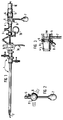
- the endoscope in the form of a resectoscope 1 is provided at the open, distal end of the shaft with an HF cutting loop 2, which can be axially displaced by a handle 3a, 3b for performing a longitudinal section, for example for removing prostate tissue.
- the eyepiece funnel 4 of the endoscope lens 5 which is releasably fixed in the work insert, onto which the distal end of the objective 6 of a camera is pushed and rotatably fixed by ball detent elements 9.
- This fixation or coupling is secured against unintentional loosening by a screw 8 engaging in the annular groove 4a of the eyepiece funnel 4.
- This screw 8 is in the version of the lens 6 of the video camera, of which only its camera head 10 is shown, screwed and provided with a stop shoulder to prevent that the screw 8 comes to rest against the bottom of the ring groove and thereby the rotation of the Objective 6 on the eyepiece funnel 4 hindered.
- the camera head is screwed into the proximal end 11 of the objective 6.
- the center of gravity of the camera lens 6 rotatably mounted on the eyepiece funnel 4 is shifted eccentrically to the axis of rotation.
- a downward weight pendulum 7 is rigidly connected to the lens 6. If necessary, this pendulum 7 can be replaced by a different pendulum with a different weight.
- the position of the objective 6 or the recording position of the video camera is maintained when the endoscope 1 needs to be rotated, specifically by swinging the camera or the camera head on the endoscope.
- the rotary movement of the endoscope can therefore not have an effect on the endoscopic image displayed on a monitor, or moving the objective 6 with the rotation of the endoscope by the pendulum is reversed or at least largely avoided from the outset.
- An eccentric shift of the camera or lens center of gravity is also possible in that the single pendulum 7 is replaced by two stabilizers arranged diagonally downwards at the side of the lens mount.
Abstract
Description
Zur Übertragung von Bildern aus Körperhöhlen und/oder zur Befunddokumentation werden Kameras, insbesondere Videokameras, verwendet, die über ihr Objektiv mit dem Okulartrichter des Endoskops lösbar, im übrigen aber starr verbindbar sind.Cameras, in particular video cameras, are used for the transmission of images from body cavities and / or for documentation of findings, which can be detached via their objective with the eyepiece funnel of the endoscope, but are otherwise rigidly connectable.
Verbindungen bzw. Schnellkupplungen der erwähnten Art sind bekannt aus den DE-U 18 40 515 und DE-U 79 18 414 sowie der DE-A 34 29 945 und der DE-B 27 57 358. Diese bekannten Ausführungen weisen den Nachteil auf, daß durch die feste Verbindung zwischen dem Okulartrichter und der Kamera ein Verdrehen der Kamera auf dem Okulartrichter nicht ohne weiteres möglich ist, wodurch die Handhabung der gesamten Einheit, bestehend aus Endoskop bzw. Endoskopoptik, Objektiv mit Schnellkupplung und Kamera, in manchen Fällen sehr ungünstig ist, insbesondere dann, wenn bei unveränderter Beobachtungsposition der Angriffsort des Behandlungsinstrumentes an einer ausgewählten Gewebestelle verändert werden soll, um dadurch beispielsweise eine Blutung stillen, eine Koagulation oder einen Gewebeschnitt vornehmen zu können.Connections or quick couplings of the type mentioned are known from DE-U 18 40 515 and DE-U 79 18 414 as well as DE-A 34 29 945 and DE-B 27 57 358. These known designs have the disadvantage that due to the fixed connection between the eyepiece funnel and the camera, it is not readily possible to turn the camera on the eyepiece funnel, which makes the handling of the entire unit, consisting of an endoscope or endoscope optics, objective with quick coupling and camera, in some cases very unfavorable in particular when the point of attack of the treatment instrument at a selected tissue site is to be changed while the observation position remains unchanged, in order to be able to stop bleeding, coagulate or cut tissue, for example.
Ein geringfügiges bzw. beschränktes Verdrehen des verwendeten Instruments, wie beispielsweise eine Koagulation-Schneid-Schlinge, ist zwar bei starrer Adaption einer Kamera am Okulartrichter einer Endoskopoptik grundsätzlich möglich, weist jedoch den Nachteil der damit gleichzeitig einhergehenden Bilddrehung auf, wodurch das mittels eines Monitors dargestellte endoskopische Bild sehr unruhig auf den Betrachter wirkt und dieser unter Umständen dadurch die Orientierung verliert.A slight or limited twisting of the instrument used, such as a coagulation cutting loop, is in principle possible with rigid adaptation of a camera to the eyepiece funnel of an endoscope optic, but has the disadvantage of the image rotation associated therewith, which means that this is shown by means of a monitor endoscopic image has a very uneasy effect on the viewer and may thereby lose orientation.
Durch die aus vorstehend genanntem Grunde vorzunehmende Korrektur der Bildlage wird der Operateur genötigt, den Arbeitsablauf zu unterbrechen, um die erforderliche Korrektur vornehmen zu können, wodurch zum einen für den Eingriff ein größerer Zeitaufwand erforderlich ist als dies für die Ausführung des Eingriffs selbst erforderlich wäre und andererseits durch die Unterbrechung und Wiederaufnahme des Eingriffes auch der geistige Arbeitsablauf des Operateurs nachteilig beeinträchtigt zumindest jedoch gestört wird.Due to the above-mentioned reason to correct the image position, the surgeon is forced to interrupt the workflow in order to be able to make the required correction, which on the one hand requires a greater amount of time for the intervention than would be necessary for the execution of the intervention itself and on the other hand, the interruption and resumption of the intervention also adversely affects the surgeon's mental workflow, but at least disturbs it.
Ein Endoskop mit mechanischer Kompensation von Bilddrehungen ist aus US-A-4 248 213 bekannt. Die bekannte Vorrichtung weist einen Adapter auf, der eine gewichts Kompensiert aufgehängte Kamera dreht.An endoscope with mechanical compensation for image rotations is known from US-A-4 248 213. The known device has an adapter that rotates a weight-compensated camera.
Die Aufgabe der Erfindung besteht daher darin, diese Nachteile zu vermeiden, dem Operateur die Durchführung eines Eingriffes in der Körperhöhle zu erleichtern, die Anforderung an die Konzentration des Operateurs zu reduzieren und den endoskopischen Eingriff sicher und schnell durchführen zu können. Die Aufgabe besteht insbesondere darin, die Kupplung zwischen Kameraobjektiv und Endoskop konstruktiv so auszubilden, daß mögliche Bilddrehungen automatisch ausgeglichen bzw. verhindert werden, ohne hierzu elektronische Meß- und Stelleinrichtungen anwenden zu müssen.The object of the invention is therefore to avoid these disadvantages, to make it easier for the surgeon to carry out an intervention in the body cavity, to reduce the requirement for the surgeon's concentration and to be able to carry out the endoscopic intervention safely and quickly. The task consists in particular in constructing the coupling between the camera lens and endoscope in such a way that possible image rotations are automatically compensated for or prevented without having to use electronic measuring and adjusting devices.
Diese Aufgabe wird durch den Anspruch 1 gelöst. Die Unteransprüche stellen spezielle Lösungen der erfindungsgemäßen Aufgabe dar.This object is solved by claim 1. The subclaims represent special solutions to the problem according to the invention.
Die Erfindung wird nachstehend anhand der Zeichnung erläutert. Es zeigen:
- Figur 1
- die Seitenansicht eines Resektoskops mit angekuppeltem Objektiv einer Videokamera,
- Figur 2
- die teilweise Ansicht auf das proximale Ende des Objektives nach Figur 1 und
- Figur 3
- einen vergrößerten Längsschnitt durch das Kameraobjektiv und benachbarte Teile des Endoskops nach Figur 1.
- Figure 1
- the side view of a resectoscope with a coupled lens of a video camera,
- Figure 2
- the partial view of the proximal end of the lens of Figure 1 and
- Figure 3
- 2 shows an enlarged longitudinal section through the camera lens and adjacent parts of the endoscope according to FIG. 1.
Das Endoskop in Form eines Resektoskops 1 ist am offenen, distalen Schaftende mit einer HF-Schneidschlinge 2 versehen, die durch eine Handhabe 3a, 3b zur Durchführung eines Längsschnittes, z.B. zum Abtragen von Prostatagewebe, axial verschiebbar ist.The endoscope in the form of a resectoscope 1 is provided at the open, distal end of the shaft with an HF cutting loop 2, which can be axially displaced by a
Am proximalen Ende des mit dem Außenschaft lösbar gekuppelten Arbeitseinsatzes befindet sich der Okulartrichter 4 der lösbar im Arbeitseinsatz festgelegten Endoskopobtik 5, auf den das distale Ende des Objektives 6 einer Kamera aufgeschoben und durch Kugelrastelemente 9 drehbar fixiert ist. Diese Fixierung bzw. Kupplung ist durch eine in die Ringnut 4a des Okulartrichters 4 eingreifende Schraube 8 gegen unbeabsichtigtes Lösen gesichert. Diese Schraube 8 ist in der Fassung des Objektives 6 der Videokamera, von der nur ihr Kamerakopf 10 gezeigt ist, verschraubbar und mit einer Anschlagschulter versehen, um zu verhindern, daß die Schraube 8 gegen den Boden der Ringnut Zur Anlage kommt und dadurch die Verdrehung des Objektivs 6 auf dem Okulartrichter 4 behindert. Der Kamerakopf ist in das proximale Ende 11 des Objektives 6 eingeschraubt.At the proximal end of the work insert, which is detachably coupled to the outer shaft, is the eyepiece funnel 4 of the endoscope lens 5, which is releasably fixed in the work insert, onto which the distal end of the objective 6 of a camera is pushed and rotatably fixed by ball
Der Schwerpunkt des verdrehbar an dem Okulartrichter 4 gelagerten Kameraobjetivs 6 ist exzentrisch zur Drehachse verlagert. Dies wird nach dem Ausführungsbeispiel dadurch erreicht, daß mit dem Objektiv 6 ein nach unten gerichtetes Gewichtspendel 7 starr verbunden ist. Dieses Pendel 7 kann bei Bedarf durch ein jeweils anderes Pendel mit abweichendem Gewicht ersetzt werden. In jedem Fall wird die Lage des Objektives 6 bzw. die Aufnahmeposition der Videokamera bei erforderlich werdender Verdrehung des Endoskops 1 beibehalten, und zwar durch Auspendeln der Kamera bzw. des Kamerakopfes am Endoskop. Es kann sich daher die Drehbewegung des Endoskops nicht auf das auf einen Monitor dargestellte endoskopische Bild auswirken bzw. es wird ein Mitbewegen des Objektives 6 mit der Verdrehung des Endoskops durch das Pendel rückgängig gemacht bzw. von vornherein zumindest weitgehend vermieden.The center of gravity of the
Es ist auch möglich, das Pendel 7 mit dem Oberende in die Ringnut 4a des Okulartrichters 4 eingreifen zu lassen, wodurch die Verbindung des freiverdrehbaren Objektivs mit dem Okulartrichter 4 sicher ist und die Sicherungsschraube 8 entfallen kann.It is also possible to let the
Eine exzentrische Verlagerung des Kamera- bzw. Objektivschwerpunktes ist auch dadurch möglich, daß das Einzelpendel 7 durch zwei im Winkel schräg nach unten divergierende, unmittelbar seitlich an der Objektivfassung angeordnete Stabilisatoren ersetzt wird.An eccentric shift of the camera or lens center of gravity is also possible in that the
Im übrigen brauchen keine gesonderten Pendel vorgesehen zu werden, wenn der Schwerpunkt der an das Endoskop angeschlossenen Kamerateile so zur Drehachse versetzt angeordnet werden kann, daß allein schon durch diese Maßnahme das Kameraobjektiv unabhängig von Verdrehungen des Endoskopes ausgependelt in seiner Position gehalten wird.Moreover, no separate pendulums need to be provided if the center of gravity of the camera parts connected to the endoscope can be arranged offset to the axis of rotation in such a way that the camera lens is held in its position independently of any twisting of the endoscope.
Claims (5)
- Endoscope (1) having a lens (6) of a camera, in particular a video camera, coupled proximally and releasably, wherein means for compensating image rotations are provided, characterised in that the camera lens (6) is mounted on the endoscope (1) to be twisted freely, and in that the centre of gravity of the camera parts (6, 7, 10, 11) connected to the endoscope is displaced eccentrically to the axis of rotation so that the camera lens (6) retains its position by oscillating when the endoscope (1) is twisted.
- Endoscope according to claim 1, characterised in that the eccentricity of the centre of gravity mentioned is achieved by means of a pendulum (7) connected to the camera lens and pointing downwards.
- Endoscope according to claim 1, characterised in that the eccentricity of the centre of gravity mentioned is achieved by means of two stabilisers arranged laterally on the lens mounting and pointing downwards at a diagonal angle.
- Endoscope according to one of claims 1 to 3, characterised in that the eyepiece funnel (4) of endoscope (1) is provided with a circular groove (4a) into which locking balls (9) situated in the camera lens mounting engage.
- Endoscope according to claim 4, characterised in that the end of a screw (8) arranged in the lens mounting or the end of pendulum (7) engages in the circular groove (4a) of the eyepiece funnel (4).
Applications Claiming Priority (2)
| Application Number | Priority Date | Filing Date | Title |
|---|---|---|---|
| DE4105326 | 1991-02-21 | ||
| DE4105326A DE4105326A1 (en) | 1991-02-21 | 1991-02-21 | ENDOSCOPE WITH PROXIMALLY CONNECTABLE CAMERA |
Publications (2)
| Publication Number | Publication Date |
|---|---|
| EP0501088A1 EP0501088A1 (en) | 1992-09-02 |
| EP0501088B1 true EP0501088B1 (en) | 1995-10-11 |
Family
ID=6425506
Family Applications (1)
| Application Number | Title | Priority Date | Filing Date |
|---|---|---|---|
| EP91710056A Expired - Lifetime EP0501088B1 (en) | 1991-02-21 | 1991-12-24 | Endoscope with proximal coupled camera |
Country Status (4)
| Country | Link |
|---|---|
| US (1) | US5307804A (en) |
| EP (1) | EP0501088B1 (en) |
| AT (1) | ATE128834T1 (en) |
| DE (2) | DE4105326A1 (en) |
Cited By (2)
| Publication number | Priority date | Publication date | Assignee | Title |
|---|---|---|---|---|
| US6529620B2 (en) | 2000-09-11 | 2003-03-04 | Pinotage, L.L.C. | System and method for obtaining and utilizing maintenance information |
| DE102015004970A1 (en) | 2015-04-20 | 2016-05-04 | Drägerwerk AG & Co. KGaA | Lighting system with a camera |
Families Citing this family (49)
| Publication number | Priority date | Publication date | Assignee | Title |
|---|---|---|---|---|
| US5588948A (en) * | 1993-02-17 | 1996-12-31 | Olympus Optical Co. Ltd. | Stereoscopic endoscope |
| NL9301210A (en) * | 1993-07-09 | 1995-02-01 | Robert Philippe Koninckx | Image display system with image position correction. |
| DE4408393A1 (en) * | 1994-03-12 | 1995-09-14 | Winter & Ibe Olympus | Endoscope with lateral cable outlets |
| US5797836A (en) * | 1995-06-07 | 1998-08-25 | Smith & Nephew, Inc. | Endoscope with relative rotation and axial motion between an optical element and an imaging device |
| US6413209B1 (en) | 1995-09-15 | 2002-07-02 | Med Images, Inc. | Imaging system with condensation control |
| US6007484A (en) | 1995-09-15 | 1999-12-28 | Image Technologies Corporation | Endoscope having elevation and azimuth control of camera |
| US6428470B1 (en) | 1995-09-15 | 2002-08-06 | Pinotage, Llc | Imaging system and components thereof |
| AU7112396A (en) * | 1995-09-15 | 1997-04-17 | Robert Lee Thompson | Surgical/diagnostic imaging device |
| US5891013A (en) | 1996-02-07 | 1999-04-06 | Pinotage, Llc | System for single-puncture endoscopic surgery |
| US5951461A (en) * | 1996-12-20 | 1999-09-14 | Nyo; Tin | Image-guided laryngoscope for tracheal intubation |
| DE29705973U1 (en) * | 1997-04-04 | 1997-06-19 | Winter & Ibe Olympus | Video endoscope with image processing device |
| DE19715507C1 (en) * | 1997-04-14 | 1999-02-04 | Storz Karl Gmbh & Co | Medical instrument with a tube-like element and an angled handle, in particular mediastinoscope, laryngoscope, diverticuloscope |
| DE19715510C2 (en) * | 1997-04-14 | 2000-05-18 | Storz Karl Gmbh & Co Kg | Endoscope with a camera module and a coupling |
| US6097423A (en) * | 1997-06-06 | 2000-08-01 | Karl Storz Imaging, Inc. | Image orientation for endoscopic video displays |
| US5989182A (en) * | 1997-12-19 | 1999-11-23 | Vista Medical Technologies, Inc. | Device-steering shaft assembly and endoscope |
| US20060004260A1 (en) * | 1999-10-14 | 2006-01-05 | Ben Boedeker | Endotracheal video device |
| US20050192481A1 (en) * | 1999-10-14 | 2005-09-01 | George Berci | Laryngoscope and camera coupling |
| US6890298B2 (en) | 1999-10-14 | 2005-05-10 | Karl Storz Gmbh & Co. Kg | Video laryngoscope with detachable light and image guides |
| US20050197533A1 (en) * | 2000-03-16 | 2005-09-08 | Medivision, Inc. | Endoscope and camera mount |
| US20030215128A1 (en) * | 2001-09-12 | 2003-11-20 | Pinotage Llc | System and method for obtaining and utilizing maintenance information |
| IL140136A (en) * | 2000-12-06 | 2010-06-16 | Intumed Ltd | Apparatus for self-guided intubation |
| DE10126542A1 (en) * | 2001-05-30 | 2003-01-02 | Winter & Ibe Olympus | Urological resectoscope with spring bridge |
| US20050054895A1 (en) * | 2003-09-09 | 2005-03-10 | Hoeg Hans David | Method for using variable direction of view endoscopy in conjunction with image guided surgical systems |
| US7232409B2 (en) * | 2003-11-20 | 2007-06-19 | Karl Storz Development Corp. | Method and apparatus for displaying endoscopic images |
| US9033871B2 (en) | 2004-04-07 | 2015-05-19 | Karl Storz Imaging, Inc. | Gravity referenced endoscopic image orientation |
| IL170404A (en) * | 2004-08-26 | 2012-03-29 | C2Cure Inc | Wireless determination of endoscope orientation |
| US7517314B2 (en) * | 2004-10-14 | 2009-04-14 | Karl Storz Development Corp. | Endoscopic imaging with indication of gravity direction |
| US7956887B2 (en) * | 2005-02-17 | 2011-06-07 | Karl Storz Imaging, Inc. | Image orienting coupling assembly |
| US8203132B2 (en) * | 2005-09-08 | 2012-06-19 | Carestream Health, Inc. | Apparatus and method for imaging ionizing radiation |
| US20100220836A1 (en) | 2005-09-08 | 2010-09-02 | Feke Gilbert D | Apparatus and method for multi-modal imaging |
| US20090281383A1 (en) * | 2005-09-08 | 2009-11-12 | Rao Papineni | Apparatus and method for external fluorescence imaging of internal regions of interest in a small animal using an endoscope for internal illumination |
| US8660631B2 (en) * | 2005-09-08 | 2014-02-25 | Bruker Biospin Corporation | Torsional support apparatus and method for craniocaudal rotation of animals |
| US7905882B1 (en) * | 2007-05-03 | 2011-03-15 | Ellman Alan G | Activator for electrosurgical handpiece |
| JP5426834B2 (en) * | 2008-03-27 | 2014-02-26 | オリンパスメディカルシステムズ株式会社 | Endoscopic imaging device |
| US8648932B2 (en) * | 2009-08-13 | 2014-02-11 | Olive Medical Corporation | System, apparatus and methods for providing a single use imaging device for sterile environments |
| AU2011230538B2 (en) | 2010-03-25 | 2016-01-07 | DePuy Synthes Products, Inc. | System and method for providing a single use imaging device for medical applications |
| JP6348061B2 (en) | 2011-05-12 | 2018-06-27 | デピュー シンセス プロダクツ, インコーポレーテッドDePuy Synthes Products, Inc. | Sub-row parallel digitizer system and method for hybrid stacked image sensor using vertical interconnect |
| WO2013158974A1 (en) | 2012-04-20 | 2013-10-24 | Vanderbilt University | Dexterous wrists for surgical intervention |
| KR102143807B1 (en) | 2012-07-26 | 2020-08-31 | 디퍼이 신테스 프로덕츠, 인코포레이티드 | Camera system with minimal area monolithic cmos image sensor |
| US10517469B2 (en) | 2013-03-15 | 2019-12-31 | DePuy Synthes Products, Inc. | Image sensor synchronization without input clock and data transmission clock |
| BR112015022884A2 (en) | 2013-03-15 | 2017-07-18 | Olive Medical Corp | minimize i / o image sensor and driver counts in endoscope applications |
| DE102014205080B4 (en) | 2014-03-19 | 2023-07-13 | Richard Wolf Gmbh | medical instrument |
| DE102015202002A1 (en) | 2015-02-05 | 2016-08-11 | Olympus Winter & Ibe Gmbh | Eyepiece device and surgical instrument with an eyepiece device |
| DE102015203351A1 (en) | 2015-02-25 | 2016-08-25 | Olympus Winter & Ibe Gmbh | Eyepiece device for a surgical instrument |
| JP6469259B2 (en) * | 2016-01-07 | 2019-02-13 | 富士フイルム株式会社 | Surgical system |
| WO2018102718A1 (en) | 2016-12-02 | 2018-06-07 | Vanderbilt University | Steerable endoscope with continuum manipulator |
| WO2019055701A1 (en) | 2017-09-13 | 2019-03-21 | Vanderbilt University | Continuum robots with multi-scale motion through equilibrium modulation |
| DE102018102385A1 (en) | 2018-02-02 | 2019-08-08 | Olympus Winter & Ibe Gmbh | Eyepiece device for a surgical instrument |
| DE102019108117A1 (en) | 2019-03-28 | 2020-10-01 | Olympus Winter & Ibe Gmbh | Method of making an endoscope |
Family Cites Families (10)
| Publication number | Priority date | Publication date | Assignee | Title |
|---|---|---|---|---|
| DE7918414U1 (en) * | 1979-10-11 | Richard Wolf Gmbh, 7134 Knittlingen | Quick coupling between a camera and an endoscope lens | |
| DE1840515U (en) * | 1961-09-05 | 1961-11-02 | Wolf Gmbh Richard | INTERMEDIATE TUBE FOR PHOTO AND FILM ENDOSCOPES. |
| US3589350A (en) * | 1968-04-04 | 1971-06-29 | Earl H Hoyt Jr | Adjustable stabilizer for archery bow |
| US4182558A (en) * | 1976-12-25 | 1980-01-08 | Olympus Optical Co., Ltd. | Camera mounting device for an endoscope |
| US4248213A (en) * | 1979-08-13 | 1981-02-03 | Syn-Optics | Articulated optical coupler |
| JPS57129407A (en) * | 1981-02-03 | 1982-08-11 | Olympus Optical Co Ltd | Hard endoscope |
| US4611888A (en) * | 1983-10-17 | 1986-09-16 | Mp Video, Inc. | Coupler for surgical endoscope and video camera |
| US4781448A (en) * | 1987-03-02 | 1988-11-01 | Medical Concepts Inc. | Zoom lens adapter for endoscopic camera |
| US4844071A (en) * | 1988-03-31 | 1989-07-04 | Baxter Travenol Laboratories, Inc. | Endoscope coupler device |
| US4851866A (en) * | 1988-07-01 | 1989-07-25 | Welch Allyn, Inc. | Air vent for camera adaptor |
-
1991
- 1991-02-21 DE DE4105326A patent/DE4105326A1/en active Granted
- 1991-12-24 AT AT91710056T patent/ATE128834T1/en not_active IP Right Cessation
- 1991-12-24 EP EP91710056A patent/EP0501088B1/en not_active Expired - Lifetime
- 1991-12-24 DE DE59106683T patent/DE59106683D1/en not_active Expired - Lifetime
-
1992
- 1992-01-24 US US07/825,210 patent/US5307804A/en not_active Expired - Fee Related
Cited By (2)
| Publication number | Priority date | Publication date | Assignee | Title |
|---|---|---|---|---|
| US6529620B2 (en) | 2000-09-11 | 2003-03-04 | Pinotage, L.L.C. | System and method for obtaining and utilizing maintenance information |
| DE102015004970A1 (en) | 2015-04-20 | 2016-05-04 | Drägerwerk AG & Co. KGaA | Lighting system with a camera |
Also Published As
| Publication number | Publication date |
|---|---|
| DE4105326C2 (en) | 1992-11-26 |
| ATE128834T1 (en) | 1995-10-15 |
| DE4105326A1 (en) | 1992-09-03 |
| EP0501088A1 (en) | 1992-09-02 |
| DE59106683D1 (en) | 1995-11-16 |
| US5307804A (en) | 1994-05-03 |
Similar Documents
| Publication | Publication Date | Title |
|---|---|---|
| EP0501088B1 (en) | Endoscope with proximal coupled camera | |
| DE19609034C2 (en) | Device for guiding surgical instruments for endoscopic surgery | |
| EP1997421B1 (en) | Video endoscope | |
| EP1105035B1 (en) | Lateral-viewing endoscope | |
| DE4405720C1 (en) | Instrument for endoscopic therapy of carpal tunnel syndrome | |
| DE102008057734B4 (en) | Videoscope | |
| DE4033916C2 (en) | ||
| DE102015113016A1 (en) | ENDOSCOPE HEAD | |
| DE102006026913A1 (en) | Surgical navigation system for e.g. orienting surgical device, has adapter to attach navigation tracker to surgical device, where effector axis of device is tracked by system when adapter is held against device in non-fixed manner | |
| EP1155776B1 (en) | Removable tool insert for endoscopic processing apparatus and such an endoscopic processing apparatus | |
| DE10042606A1 (en) | Medical instrument has two interfitting cannulas with curvature altered by twisting by means of cog wheels, or drive mechanism. | |
| EP0496110A2 (en) | Endoscope for transurethral operation | |
| DE102020211137A1 (en) | DETACHABLE ENDOSCOPE WITH AN ADJUSTABLE BENDING ANGLE | |
| DE102017107978B4 (en) | Endoscope head with swiveling camera and working channel unit | |
| EP2438844A2 (en) | Articulated section of a shaft for an endoscopic instrument | |
| EP0393343B1 (en) | Uretero-renoscope | |
| EP4011271A1 (en) | Endoscope with rotary drum and operating method | |
| EP1437978A1 (en) | Device for adaptation of in particular surgical instruments such as pointing devices | |
| DE19955180B4 (en) | laryngoscope | |
| DE102011012426B4 (en) | Endoscopic instrument for one-hand operation | |
| EP0527541B1 (en) | Endoscope | |
| DE102021119204A1 (en) | Camera head for endoscopes | |
| DE19825763C2 (en) | Endoscope system for spinal surgery | |
| DE202023104936U1 (en) | Medical binocular magnifier | |
| DE102022113124A1 (en) | Handle for medical endoscopes and endoscope system |
Legal Events
| Date | Code | Title | Description |
|---|---|---|---|
| PUAI | Public reference made under article 153(3) epc to a published international application that has entered the european phase |
Free format text: ORIGINAL CODE: 0009012 |
|
| AK | Designated contracting states |
Kind code of ref document: A1 Designated state(s): AT CH DE FR GB LI |
|
| 17P | Request for examination filed |
Effective date: 19930129 |
|
| 17Q | First examination report despatched |
Effective date: 19950127 |
|
| GRAA | (expected) grant |
Free format text: ORIGINAL CODE: 0009210 |
|
| AK | Designated contracting states |
Kind code of ref document: B1 Designated state(s): AT CH DE FR GB LI |
|
| PG25 | Lapsed in a contracting state [announced via postgrant information from national office to epo] |
Ref country code: GB Effective date: 19951011 |
|
| REF | Corresponds to: |
Ref document number: 128834 Country of ref document: AT Date of ref document: 19951015 Kind code of ref document: T |
|
| REF | Corresponds to: |
Ref document number: 59106683 Country of ref document: DE Date of ref document: 19951116 |
|
| PGFP | Annual fee paid to national office [announced via postgrant information from national office to epo] |
Ref country code: FR Payment date: 19951221 Year of fee payment: 5 |
|
| PG25 | Lapsed in a contracting state [announced via postgrant information from national office to epo] |
Ref country code: AT Effective date: 19951224 |
|
| PG25 | Lapsed in a contracting state [announced via postgrant information from national office to epo] |
Ref country code: LI Effective date: 19951231 Ref country code: CH Effective date: 19951231 |
|
| PGFP | Annual fee paid to national office [announced via postgrant information from national office to epo] |
Ref country code: DE Payment date: 19960205 Year of fee payment: 5 |
|
| ET | Fr: translation filed | ||
| PG25 | Lapsed in a contracting state [announced via postgrant information from national office to epo] |
Ref country code: DE Effective date: 19960228 |
|
| GBV | Gb: ep patent (uk) treated as always having been void in accordance with gb section 77(7)/1977 [no translation filed] |
Effective date: 19951011 |
|
| REG | Reference to a national code |
Ref country code: CH Ref legal event code: PL |
|
| PLBE | No opposition filed within time limit |
Free format text: ORIGINAL CODE: 0009261 |
|
| STAA | Information on the status of an ep patent application or granted ep patent |
Free format text: STATUS: NO OPPOSITION FILED WITHIN TIME LIMIT |
|
| 26N | No opposition filed | ||
| PG25 | Lapsed in a contracting state [announced via postgrant information from national office to epo] |
Ref country code: FR Effective date: 19970829 |
|
| REG | Reference to a national code |
Ref country code: FR Ref legal event code: ST |