EP0448728A1 - Exhaust apparatus in saddle type vehicle - Google Patents
Exhaust apparatus in saddle type vehicle Download PDFInfo
- Publication number
- EP0448728A1 EP0448728A1 EP90915196A EP90915196A EP0448728A1 EP 0448728 A1 EP0448728 A1 EP 0448728A1 EP 90915196 A EP90915196 A EP 90915196A EP 90915196 A EP90915196 A EP 90915196A EP 0448728 A1 EP0448728 A1 EP 0448728A1
- Authority
- EP
- European Patent Office
- Prior art keywords
- muffler
- exhaust
- seat
- exhaust pipe
- rear cowl
- Prior art date
- Legal status (The legal status is an assumption and is not a legal conclusion. Google has not performed a legal analysis and makes no representation as to the accuracy of the status listed.)
- Granted
Links
Images


Classifications
-
- F—MECHANICAL ENGINEERING; LIGHTING; HEATING; WEAPONS; BLASTING
- F01—MACHINES OR ENGINES IN GENERAL; ENGINE PLANTS IN GENERAL; STEAM ENGINES
- F01N—GAS-FLOW SILENCERS OR EXHAUST APPARATUS FOR MACHINES OR ENGINES IN GENERAL; GAS-FLOW SILENCERS OR EXHAUST APPARATUS FOR INTERNAL COMBUSTION ENGINES
- F01N13/00—Exhaust or silencing apparatus characterised by constructional features ; Exhaust or silencing apparatus, or parts thereof, having pertinent characteristics not provided for in, or of interest apart from, groups F01N1/00 - F01N5/00, F01N9/00, F01N11/00
- F01N13/08—Other arrangements or adaptations of exhaust conduits
-
- B—PERFORMING OPERATIONS; TRANSPORTING
- B60—VEHICLES IN GENERAL
- B60K—ARRANGEMENT OR MOUNTING OF PROPULSION UNITS OR OF TRANSMISSIONS IN VEHICLES; ARRANGEMENT OR MOUNTING OF PLURAL DIVERSE PRIME-MOVERS IN VEHICLES; AUXILIARY DRIVES FOR VEHICLES; INSTRUMENTATION OR DASHBOARDS FOR VEHICLES; ARRANGEMENTS IN CONNECTION WITH COOLING, AIR INTAKE, GAS EXHAUST OR FUEL SUPPLY OF PROPULSION UNITS IN VEHICLES
- B60K13/00—Arrangement in connection with combustion air intake or gas exhaust of propulsion units
- B60K13/04—Arrangement in connection with combustion air intake or gas exhaust of propulsion units concerning exhaust
-
- B—PERFORMING OPERATIONS; TRANSPORTING
- B60—VEHICLES IN GENERAL
- B60Y—INDEXING SCHEME RELATING TO ASPECTS CROSS-CUTTING VEHICLE TECHNOLOGY
- B60Y2200/00—Type of vehicle
- B60Y2200/10—Road Vehicles
- B60Y2200/12—Motorcycles, Trikes; Quads; Scooters
-
- B—PERFORMING OPERATIONS; TRANSPORTING
- B60—VEHICLES IN GENERAL
- B60Y—INDEXING SCHEME RELATING TO ASPECTS CROSS-CUTTING VEHICLE TECHNOLOGY
- B60Y2200/00—Type of vehicle
- B60Y2200/10—Road Vehicles
- B60Y2200/12—Motorcycles, Trikes; Quads; Scooters
- B60Y2200/124—Buggies, Quads
-
- F—MECHANICAL ENGINEERING; LIGHTING; HEATING; WEAPONS; BLASTING
- F01—MACHINES OR ENGINES IN GENERAL; ENGINE PLANTS IN GENERAL; STEAM ENGINES
- F01N—GAS-FLOW SILENCERS OR EXHAUST APPARATUS FOR MACHINES OR ENGINES IN GENERAL; GAS-FLOW SILENCERS OR EXHAUST APPARATUS FOR INTERNAL COMBUSTION ENGINES
- F01N2340/00—Dimensional characteristics of the exhaust system, e.g. length, diameter or volume of the apparatus; Spatial arrangements of exhaust apparatuses
- F01N2340/04—Dimensional characteristics of the exhaust system, e.g. length, diameter or volume of the apparatus; Spatial arrangements of exhaust apparatuses characterised by the arrangement of an exhaust pipe, manifold or apparatus in relation to vehicle frame or particular vehicle parts
-
- F—MECHANICAL ENGINEERING; LIGHTING; HEATING; WEAPONS; BLASTING
- F01—MACHINES OR ENGINES IN GENERAL; ENGINE PLANTS IN GENERAL; STEAM ENGINES
- F01N—GAS-FLOW SILENCERS OR EXHAUST APPARATUS FOR MACHINES OR ENGINES IN GENERAL; GAS-FLOW SILENCERS OR EXHAUST APPARATUS FOR INTERNAL COMBUSTION ENGINES
- F01N2590/00—Exhaust or silencing apparatus adapted to particular use, e.g. for military applications, airplanes, submarines
- F01N2590/04—Exhaust or silencing apparatus adapted to particular use, e.g. for military applications, airplanes, submarines for motorcycles
Definitions
- the present invention relates to exhaust apparatuses for straddle seat type vehicles such as two- or three-wheeled motorized vehicles.
- exhaust structures exist for straddle seat type vehicles in which an internal combustion engine is provided in a generally central part of the longitudinal direction of the chassis an exhaust pipe which is connected to this internal combustion engine is guided in the downward and rearward direction of the chassis, and moreover, this exhaust pipe is connected to a muffler which is provided at the rear side of the chassis.
- the muffler is provided at the rear side of the chassis, so that the muffler is exposed to the exterior and it is a simple matter to bring the muffler into contact with the air which flows by at the time of the operation of the vehicle, so that efficient cooling of the muffler, which tends to become heated during operation of the vehicle, can be conducted.
- the present invention is an exhaust apparatus for straddle seat type vehicles which is provided with an exhaust pipe which is connected to an internal combustion engine which is provided in the center of a chassis which is provided with front and rear wheels and a muffler which is connected to this exhaust pipe; a rear cowl is provided to the rear of the seat and the muffler is provided within the rear cowl and the exhaust pipe which is connected to the muffler passes through a position beneath the seat and is connected to the internal combustion engine.
- the muffler is located to the rear of the seat, it is possible to provide a muffler which is wider than the seat. In this case, it is possible to increase the capacity of the muffler.
- the rear cowl parts which extend to the left and right. Air guiding holes are formed in the front surfaces of these extended parts, air exhaust holes are formed in the rear surface of the rear cowl, and the rear part of the exhaust pipe is exposed along a cooling passage which connects the air guiding holes and the air exhaust holes, and thus it is possible to increase the amount of ventilation within the rear cowl.
- the cross sectional shape of the rear cowl is a shape which surrounds the muffler, and holes which communicate the inside and outside of the rear cowl are formed in the upper and lower parts thereof, so that it is possible to increase the ventilation within the rear cowl.
- an exhaust collector chamber is provided between the internal combustion engine and the rear wheel, and it is possible to bend the exhaust pipe which is provided beneath the seat and connected to this exhaust collector chamber.
- the exhaust pipe which is positioned below the seat is given a flat shape so as to increase its width in the lateral direction of the chassis, and thus it is possible to prevent the interference of the rear wheel and the exhaust pipe.
- Figures 1 ⁇ 5 show a first embodiment of the invention
- Figure 1 is a side view showing a two-wheeled motor vehicle
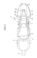
- Figure 2 is a top view of the same vehicle
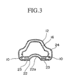
- Figure 3 is a cut-away cross sectional view along the line III-III in Figure 1
- Figure 4 is a cut-away cross sectional view along the line IV-IV in Figure 1
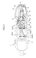
- Figure 5 is a top view of the main components.
- Figures 6 ⁇ 10 show a second embodiment of the invention
- Figure 6 is a side view of a two-wheeled motor vehicle
- Figure 7 is a top view of the main components
- Figure 8 is a side view of the main components
- Figure 9 is a view in the direction of the arrow A in Figure 8
- Figure 10 is a vertical cross sectional view of the rear part of the rear cowl.
- Reference numeral 1 indicates a two-wheeled motor vehicle which is a straddle seat type vehicle to which the present invention is applied.
- This two-wheeled motor vehicle 1 is provided with chassis frame 2, front fork 3 which is inserted freely rotatably in the forward direction of this chassis frame 2, steering handle 4 which is inserted in the upper end part of the front fork 3, front wheel 5 which is inserted freely rotatably at the lower end part of the front fork 3, internal combustion engine 6 which is provided in a suspended manner at the lower part of the chassis frame 2, cantilevered swing arm 7 which is inserted freely swingably in the rearward direction of the lower part of chassis frame 2, rear wheel 8 which is inserted freely rotatably at the swinging end part of this swing arm 7, fuel tank 9 which is inserted in a position which is in an upward direction from the chassis frame 2 and the internal combustion engine 6, seat rail 10 which is provided in an extending manner from the upper part of the rear of chassis frame 2 in the direction of the upper part of rear wheel 8, seat 11 which is inserted above seat rail 10
- the internal combustion engine 6 is a V-type, 4-cylinder engine which has cylinders 17 (17a, 17b) which are distributed to the front and rear.
- the exhaust pipe 13 is provided with a pair of exhaust pipes 13a for use with the front cylinders 17a and a pair of exhaust pipes 13b for use with the rear cylinders 17b.
- the collector chamber 14 is provided to the rear of the internal combustion engine 6 and beneath the pivot part 18 of the swing arm 7 and has a flat shape with a large width in the lateral direction of the chassis.
- the pair of exhaust pipes 13a for use with the front chambers 17a are connected to the front surface of the collector chamber 14 after passing beneath the internal combustion engine 6.
- the rear cowl 12 is formed with a greater width than seat 11, as shown in Figure 2, and air guidance holes 19 and 20 which communicate the inside and outside of rear cowl 12 are formed in the front end surfaces of both sides of rear cowl 12 and roughly in the lateral center of the upper surface, and furthermore, a louver-shaped air exhaust hole 21 is formed in the rear surface thereof.
- holes are formed in the bottom part of rear cowl 12, and these are closed by means of the insertion of the rear fender 22 which is provided above rear wheel 8 and accordingly, this rear cowl 12 has the shape of a case which surrounds the muffler 16.
- a concavity 22a is formed running in the lengthwise direction of rear fender 22 in a position which corresponds to the rear wheel 8, and on both sides of this concavity 22a, air holes 23 which communicate the inside and outside rear cowl 12 are formed.
- the external shape of the muffler 16 conforms almost entirely to the inner surface shape of the cavity which is formed by rear cowl 12 and rear fender 22 and an air guiding passage 24 which has an almost entirely fixed distance from the inner surface of the cavity over the entire length thereof.
- the rearward exhaust pipe 15 which connects the muffler 16 and the collector chamber 14 is provided between the approximately central portion of the front surface of muffler 16 and the part of the collector chamber 14 at which the exhaust pipes 13b which are used for the rear cylinder 17b are connected; this pipe begins in a nearly vertical manner from collector chamber 14 and is then bent along seat rail 10 and is connected to muffler 16.
- the part of the rearward exhaust pipe 15 which is placed along seat rail 10 has a flat shape which has a large width in the lateral direction of the chassis, as shown in Figure 4.
- the swing arm 7 comprises, in the present example, a base part 7a which covers the collector chamber 14 and a support part 7b which extends from this base part 7a to the left side of the rear wheel 8.
- notches 7c are formed for the purpose of avoiding the mutual obstruction of the pair of exhaust pipes 13b which are connected to the collector chamber 14 and the rearward exhaust pipe 15, and in addition, a passage hole 25 is formed in a vertical direction in approximately the central part of the base plate 7a.
- a ring mechanism 26 is positioned in the bottom surface of the base part 7a so as to be positioned below the passage hole 25.
- the lower end part of a rear cushion unit 27 which is inserted into the passage hole 25 is connected to this ring mechanism 26.
- this rear cushion unit 27 is supported by means of a bracket 28 which is connected to the rear end upper part of the chassis frame 2.
- rear cowl 12 is provided to the rear of seat 11
- muffler 16 is provided within rear cowl 12
- the exhaust pipe 15 which is connected to muffler 16 is bent downwards at a position below seat 11 and is connected to internal combustion engine 6. Due to this, even in the case in which the capacity of the muffler 16 is enlarged, there is no extension of muffler 16 to the right and left at the position of seat 11, so that it is possible to increase the degree of freedom of the riding position of the operator.
- the muffler 16 is provided in the rear cowl 12 and it has a larger width than seat 11 so that it is possible to increase the width dimension of muffler 16 while controlling the increase in the lateral extension of the chassis and as a result, it is possible to enlarge the capacity of muffler 16.
- parts 12a which extend to the right and left are provided on rear cowl 12 and air guidance holes 19 are formed in the front surfaces of these extended parts 12a, and an air exhaust hole 21 is formed in the rear surface of the rear cowl, and muffler 16, which is provided to the rear of rearward exhaust pipe 15, is provided along the cooling passage which connects air guidance holes 19 and air exhaust hole 21 so that it is possible to directly cause cooling air to flow from the front to the rear within rear cowl 12, and thus the air flow characteristics are good, so that the muffler 16 does not tend to become surrounded by hot air, and it is possible to concentrate a large amount of cooling air, and thus, it is possible to increase the cooling ability of muffler 16.
- rear cowl 12 is such that it encloses muffler 16, and air guidance holes 20 are formed in the upper part of rear cowl 12, and holes 23 are formed in the rear fender 22 which is inserted at the lower part of rear cowl 12 so that it is possible to increase the amount of air which passes through rear cowl 12 and to further increase the cooling ability of the muffler.
- the collector chamber 14 is provided between the internal combustion engine 6 and the rear wheel 8, and the rearward exhaust pipe 15 which is provided below seat 11 is connected to this collector chamber 14, so that the mutual interference of the rearward exhaust pipe 15 and the rear wheel 8 can be prevented, and it is possible to increase the spatial efficiency.
- the rearward exhaust pipe 15 which is positioned beneath the seat 11 has a flat shape such that the width thereof is large in the lateral direction of the chassis, so that as a result of this, it is possible to prevent the mutual interference of the rearward exhaust pipe 15 and the rear wheel 8.
- the rearward exhaust pipe 15 which is connected to the muffler 16 in a roughly central part of the chassis, and the disposal thereof at a position at which a sheltering part exists between it and the rider becomes possible, and thus the countermeasures for the heat from the exhaust system becomes simple.
- the rear wheel 8 is pivotally supported on cantilever swing arm 7 so as to be freely swingable in an up and down direction of the chassis, and the rearward exhaust pipe 15 is extended in an up and down direction in front of the rear wheel 8, so that it is possible to remove the rear wheel 8 from the side thereof and thus maintenance is facilitated.
- the rear cowl 12 is formed with a greater width than seat 11
- the muffler 16 is provided within this rear cowl 12 and the muffler 16 has a shape which conforms to the inner surface of rear cowl 12, so that the width dimension of the muffler 16 can be expanded while controlling the amount of the lateral extension of the chassis, and as a result, an increase in capacity of the muffler 16 becomes possible.
- the space between the muffler 16 and a rider seated on seat 11 is sheltered by means of rear cowl 12, and thus the transmission of heat to the seat 11 can be greatly controlled.
- the degree of freedom in the establishment of the spacing between seat 11 and muffler 16 becomes large and the degree of freedom in the design is increased, and by means of placing the muffler 16 within the rear cowl 12, an increase in appearance can be achieved.
- rear cowl 12 is closed up by means of rear fender 22, so that the sheltering of the muffler 16 from the outside is reliably conducted, and by means of the formation of an air passage 24 having a case-shape around muffler 16, and by means of the guidance of the air flow which is guided into rear cowl 12 when the vehicle is in operation and passes the outer surface of the muffler 16, it is possible to increase the ability to cool muffler 16.
- the indicated shapes and dimensions of the parts of the structure shown are all examples; it is possible to alter them in various ways based on the demands of the design or the structure of the particular vehicles.
- one muffler 16 was provided; however, in this example, two mufflers 36 are disposed in the rear cowl 12, as shown in Figure 7.
- reference numeral 50 indicates a tail lamp housing in which a tail lamp unit is disposed and a lens surface 52, which is exposed in a rearward direction.
- a concavity 53 having a straight line form in a left and right direction is formed.
- This concavity 53 is in a position which overlies the bulb 54 ( Figure 9) when viewed from the rear. In this way, in comparison with a uniform lens surface 52, the interior of concavity 53 does not become soiled during operation in rainy weather, and the visibility of the tail lamp is increased.
- reference numeral 55 indicates an upper water radiator
- reference numeral 56 indicates an oil cooler
- reference numeral 57 indicates a lower water radiator
- the exhaust apparatus for straddle seat type vehicles can be used as an exhaust apparatus for two-wheeled motor vehicles and is especially applicable in cases in which an increase in capacity of the muffler and an improvement in cooling efficiency is desired.
Abstract
Description
- The present invention relates to exhaust apparatuses for straddle seat type vehicles such as two- or three-wheeled motorized vehicles.
- As disclosed in Japanese Patent Application Second Publication No. Hei 1-44553, Japanese Patent Application Second Publication No. Hei 1-34198, and Japanese Patent Application First Publication No. Sho 64-12986, exhaust structures exist for straddle seat type vehicles in which an internal combustion engine is provided in a generally central part of the longitudinal direction of the chassis an exhaust pipe which is connected to this internal combustion engine is guided in the downward and rearward direction of the chassis, and moreover, this exhaust pipe is connected to a muffler which is provided at the rear side of the chassis.
- In accordance with this structure, the muffler is provided at the rear side of the chassis, so that the muffler is exposed to the exterior and it is a simple matter to bring the muffler into contact with the air which flows by at the time of the operation of the vehicle, so that efficient cooling of the muffler, which tends to become heated during operation of the vehicle, can be conducted.
- However, in the conventional technology described above, because the muffler is provided at the side of the chassis, the increase in capacity of the muffler itself is limited as a result of the limitation in the width of the chassis. Furthermore, since a sufficient gap must be maintained between the rider and the muffler, difficulties arise, such as the restriction of the freedom in the layout of the muffler and the exhaust pipe which is connected thereto.
- Accordingly, countermeasures have been conventionally sought for these difficulties, and the present invention solves the problems which are mentioned above.
- The present invention is an exhaust apparatus for straddle seat type vehicles which is provided with an exhaust pipe which is connected to an internal combustion engine which is provided in the center of a chassis which is provided with front and rear wheels and a muffler which is connected to this exhaust pipe; a rear cowl is provided to the rear of the seat and the muffler is provided within the rear cowl and the exhaust pipe which is connected to the muffler passes through a position beneath the seat and is connected to the internal combustion engine. By means of this structure, even in the case of an increase in capacity of the muffler, an increase in lateral size of the muffler at the seat part does not occur, and it is possible to increase the degree of freedom of the riding position of the operator.
- Furthermore, since the muffler is located to the rear of the seat, it is possible to provide a muffler which is wider than the seat. In this case, it is possible to increase the capacity of the muffler.
- In addition, it is possible to provide, in the rear cowl, parts which extend to the left and right. Air guiding holes are formed in the front surfaces of these extended parts, air exhaust holes are formed in the rear surface of the rear cowl, and the rear part of the exhaust pipe is exposed along a cooling passage which connects the air guiding holes and the air exhaust holes, and thus it is possible to increase the amount of ventilation within the rear cowl. Furthermore, the cross sectional shape of the rear cowl is a shape which surrounds the muffler, and holes which communicate the inside and outside of the rear cowl are formed in the upper and lower parts thereof, so that it is possible to increase the ventilation within the rear cowl.
- In addition, an exhaust collector chamber is provided between the internal combustion engine and the rear wheel, and it is possible to bend the exhaust pipe which is provided beneath the seat and connected to this exhaust collector chamber.
- In addition, the exhaust pipe which is positioned below the seat is given a flat shape so as to increase its width in the lateral direction of the chassis, and thus it is possible to prevent the interference of the rear wheel and the exhaust pipe.
- Furthermore, it is preferable to support the rear wheel freely swingably in an up and down direction of the chassis on a cantilevered swing arm and also to provide the exhaust pipe in a bent manner from a position beneath the seat to the forward part of the rear wheel. By means of this, it is possible to remove the rear wheel from the side and thus operations such as maintenance and the like are facilitated.
- The appended drawings show a preferred embodiment of the present invention.
- Figures 1∼5 show a first embodiment of the invention; Figure 1 is a side view showing a two-wheeled motor vehicle, Figure 2 is a top view of the same vehicle, Figure 3 is a cut-away cross sectional view along the line III-III in Figure 1, Figure 4 is a cut-away cross sectional view along the line IV-IV in Figure 1, and Figure 5 is a top view of the main components.
- Figures 6∼10 show a second embodiment of the invention; Figure 6 is a side view of a two-wheeled motor vehicle, Figure 7 is a top view of the main components, Figure 8 is a side view of the main components, Figure 9 is a view in the direction of the arrow A in Figure 8, and Figure 10 is a vertical cross sectional view of the rear part of the rear cowl.
- The first embodiment of this invention will be explained based on Figures 1∼5.
- Reference numeral 1 indicates a two-wheeled motor vehicle which is a straddle seat type vehicle to which the present invention is applied. This two-wheeled motor vehicle 1 is provided with
chassis frame 2,front fork 3 which is inserted freely rotatably in the forward direction of thischassis frame 2,steering handle 4 which is inserted in the upper end part of thefront fork 3,front wheel 5 which is inserted freely rotatably at the lower end part of thefront fork 3,internal combustion engine 6 which is provided in a suspended manner at the lower part of thechassis frame 2, cantileveredswing arm 7 which is inserted freely swingably in the rearward direction of the lower part ofchassis frame 2,rear wheel 8 which is inserted freely rotatably at the swinging end part of thisswing arm 7,fuel tank 9 which is inserted in a position which is in an upward direction from thechassis frame 2 and theinternal combustion engine 6,seat rail 10 which is provided in an extending manner from the upper part of the rear ofchassis frame 2 in the direction of the upper part ofrear wheel 8, seat 11 which is inserted aboveseat rail 10 and to the rear offuel tank 9,rear cowl 12 which is affixed toseat rail 10 at the rear of seat 11,exhaust pipe 13 which is connected tointernal combustion engine 6,collector chamber 14 which is connected to the downstream side ofexhaust pipe 13, rearwardexhaust pipe 15 which is provided extending from thiscollector chamber 14, andmuffler 16 which is connected to the downstream side of this rearwardexhaust pipe 15. - In greater detail, the
internal combustion engine 6 is a V-type, 4-cylinder engine which has cylinders 17 (17a, 17b) which are distributed to the front and rear. Theexhaust pipe 13 is provided with a pair ofexhaust pipes 13a for use with thefront cylinders 17a and a pair ofexhaust pipes 13b for use with therear cylinders 17b. - Furthermore, the
collector chamber 14 is provided to the rear of theinternal combustion engine 6 and beneath thepivot part 18 of theswing arm 7 and has a flat shape with a large width in the lateral direction of the chassis. The pair ofexhaust pipes 13a for use with thefront chambers 17a are connected to the front surface of thecollector chamber 14 after passing beneath theinternal combustion engine 6. - On the other hand, the
rear cowl 12 is formed with a greater width than seat 11, as shown in Figure 2, andair guidance holes rear cowl 12 are formed in the front end surfaces of both sides ofrear cowl 12 and roughly in the lateral center of the upper surface, and furthermore, a louver-shapedair exhaust hole 21 is formed in the rear surface thereof. As shown in Figure 3, holes are formed in the bottom part ofrear cowl 12, and these are closed by means of the insertion of therear fender 22 which is provided aboverear wheel 8 and accordingly, thisrear cowl 12 has the shape of a case which surrounds themuffler 16. Furthermore, aconcavity 22a is formed running in the lengthwise direction ofrear fender 22 in a position which corresponds to therear wheel 8, and on both sides of thisconcavity 22a,air holes 23 which communicate the inside and outsiderear cowl 12 are formed. - In addition, as shown in Figures 1∼3, the external shape of the
muffler 16 conforms almost entirely to the inner surface shape of the cavity which is formed byrear cowl 12 andrear fender 22 and anair guiding passage 24 which has an almost entirely fixed distance from the inner surface of the cavity over the entire length thereof. - Furthermore, the
rearward exhaust pipe 15 which connects themuffler 16 and thecollector chamber 14 is provided between the approximately central portion of the front surface ofmuffler 16 and the part of thecollector chamber 14 at which theexhaust pipes 13b which are used for therear cylinder 17b are connected; this pipe begins in a nearly vertical manner fromcollector chamber 14 and is then bent alongseat rail 10 and is connected tomuffler 16. - Furthermore, the part of the
rearward exhaust pipe 15 which is placed alongseat rail 10 has a flat shape which has a large width in the lateral direction of the chassis, as shown in Figure 4. As shown in Figure 5, theswing arm 7 comprises, in the present example, abase part 7a which covers thecollector chamber 14 and asupport part 7b which extends from thisbase part 7a to the left side of therear wheel 8. - In
base part 7a,notches 7c are formed for the purpose of avoiding the mutual obstruction of the pair ofexhaust pipes 13b which are connected to thecollector chamber 14 and therearward exhaust pipe 15, and in addition, apassage hole 25 is formed in a vertical direction in approximately the central part of thebase plate 7a. Aring mechanism 26 is positioned in the bottom surface of thebase part 7a so as to be positioned below thepassage hole 25. The lower end part of arear cushion unit 27 which is inserted into thepassage hole 25 is connected to thisring mechanism 26. - As shown in Figure 1, the upper end part of this
rear cushion unit 27 is supported by means of abracket 28 which is connected to the rear end upper part of thechassis frame 2. - Next, the operation of the exhaust apparatus of the first example will be explained.
- In the exhaust apparatus of the present example,
rear cowl 12 is provided to the rear of seat 11,muffler 16 is provided withinrear cowl 12, and theexhaust pipe 15 which is connected tomuffler 16 is bent downwards at a position below seat 11 and is connected tointernal combustion engine 6. Due to this, even in the case in which the capacity of themuffler 16 is enlarged, there is no extension ofmuffler 16 to the right and left at the position of seat 11, so that it is possible to increase the degree of freedom of the riding position of the operator. - Furthermore, the
muffler 16 is provided in therear cowl 12 and it has a larger width than seat 11 so that it is possible to increase the width dimension ofmuffler 16 while controlling the increase in the lateral extension of the chassis and as a result, it is possible to enlarge the capacity ofmuffler 16. - Furthermore,
parts 12a which extend to the right and left are provided onrear cowl 12 andair guidance holes 19 are formed in the front surfaces of these extendedparts 12a, and anair exhaust hole 21 is formed in the rear surface of the rear cowl, andmuffler 16, which is provided to the rear of rearwardexhaust pipe 15, is provided along the cooling passage which connectsair guidance holes 19 andair exhaust hole 21 so that it is possible to directly cause cooling air to flow from the front to the rear withinrear cowl 12, and thus the air flow characteristics are good, so that themuffler 16 does not tend to become surrounded by hot air, and it is possible to concentrate a large amount of cooling air, and thus, it is possible to increase the cooling ability ofmuffler 16. - Furthermore, the cross sectional shape of
rear cowl 12 is such that it enclosesmuffler 16, andair guidance holes 20 are formed in the upper part ofrear cowl 12, andholes 23 are formed in therear fender 22 which is inserted at the lower part ofrear cowl 12 so that it is possible to increase the amount of air which passes throughrear cowl 12 and to further increase the cooling ability of the muffler. - In addition, the
collector chamber 14 is provided between theinternal combustion engine 6 and therear wheel 8, and therearward exhaust pipe 15 which is provided below seat 11 is connected to thiscollector chamber 14, so that the mutual interference of therearward exhaust pipe 15 and therear wheel 8 can be prevented, and it is possible to increase the spatial efficiency. - Furthermore, the
rearward exhaust pipe 15 which is positioned beneath the seat 11 has a flat shape such that the width thereof is large in the lateral direction of the chassis, so that as a result of this, it is possible to prevent the mutual interference of therearward exhaust pipe 15 and therear wheel 8. By means of this, it becomes possible to dispose therearward exhaust pipe 15 which is connected to themuffler 16 in a roughly central part of the chassis, and the disposal thereof at a position at which a sheltering part exists between it and the rider becomes possible, and thus the countermeasures for the heat from the exhaust system becomes simple. - Furthermore, the
rear wheel 8 is pivotally supported oncantilever swing arm 7 so as to be freely swingable in an up and down direction of the chassis, and therearward exhaust pipe 15 is extended in an up and down direction in front of therear wheel 8, so that it is possible to remove therear wheel 8 from the side thereof and thus maintenance is facilitated. - Furthermore, the
rear cowl 12 is formed with a greater width than seat 11, themuffler 16 is provided within thisrear cowl 12 and themuffler 16 has a shape which conforms to the inner surface ofrear cowl 12, so that the width dimension of themuffler 16 can be expanded while controlling the amount of the lateral extension of the chassis, and as a result, an increase in capacity of themuffler 16 becomes possible. - Furthermore, the space between the
muffler 16 and a rider seated on seat 11 is sheltered by means ofrear cowl 12, and thus the transmission of heat to the seat 11 can be greatly controlled. - Accordingly, the degree of freedom in the establishment of the spacing between seat 11 and
muffler 16 becomes large and the degree of freedom in the design is increased, and by means of placing themuffler 16 within therear cowl 12, an increase in appearance can be achieved. - In addition, the lower part of
rear cowl 12 is closed up by means ofrear fender 22, so that the sheltering of themuffler 16 from the outside is reliably conducted, and by means of the formation of anair passage 24 having a case-shape aroundmuffler 16, and by means of the guidance of the air flow which is guided intorear cowl 12 when the vehicle is in operation and passes the outer surface of themuffler 16, it is possible to increase the ability to coolmuffler 16. - In this case, a
muffler 16 with a great width is not necessary; the effects of the invention would be unaffected if a normal cylindrical muffler were used. - Furthermore, since a
rear cowl 12 is used and arear fender 22 is attached thereto, no special materials are necessary at the time of the attachment ofrear fender 22, so that the structure can be simplified. - In the example, the indicated shapes and dimensions of the parts of the structure shown are all examples; it is possible to alter them in various ways based on the demands of the design or the structure of the particular vehicles.
- Next, the second example of the present invention will be explained based on Figures 6∼10.
- In the explanation of the second example, those structures which are common to the above-described first example are identically numbered and an explanation of such structures is omitted, so that only those structures which differ will be explained here.
- In this second example, in addition to the air guidance holes 19 and 20, two of each of the air guidance holes 39 and 40 are formed in the upper surface of rear cowl 12 (Figure 7) . Furthermore, in the lower part of
rear cowl 12, in addition toair exhaust hole 21, anair exhaust hole 34 is formed (Figures 8 and 9). - In addition, in the above example, one
muffler 16 was provided; however, in this example, two mufflers 36 are disposed in therear cowl 12, as shown in Figure 7. - Furthermore, in Figure 10,
reference numeral 50 indicates a tail lamp housing in which a tail lamp unit is disposed and alens surface 52, which is exposed in a rearward direction. In the central part of thelens surface 52, aconcavity 53 having a straight line form in a left and right direction is formed. Thisconcavity 53 is in a position which overlies the bulb 54 (Figure 9) when viewed from the rear. In this way, in comparison with auniform lens surface 52, the interior ofconcavity 53 does not become soiled during operation in rainy weather, and the visibility of the tail lamp is increased. - In Figure 6, reference numeral 55 indicates an upper water radiator,
reference numeral 56 indicates an oil cooler, andreference numeral 57 indicates a lower water radiator. - The remaining structure and operational effects of the second example explained above are identical to those of the first example, so that an explanation thereof is omitted.
- As explained above, the exhaust apparatus for straddle seat type vehicles according to the present invention can be used as an exhaust apparatus for two-wheeled motor vehicles and is especially applicable in cases in which an increase in capacity of the muffler and an improvement in cooling efficiency is desired.
Claims (7)
- An exhaust apparatus for straddle seat type vehicles in which an internal combustion engine is provided at the center of a chassis having front and rear wheels and which is provided with an exhaust pipe which is connected to the internal combustion engine and a muffler which is connected to the exhaust pipe; in which apparatus a rear cowl is provided to the rear of the seat and the muffler is provided within the rear cowl, and the exhaust pipe which is connected to the muffler passes through a position below the seat and is connected to the internal combustion engine.
- An exhaust apparatus for straddle seat type vehicles in accordance with claim 1, in which the muffler has a greater width than the seat.
- An exhaust apparatus for straddle seat type vehicles in accordance with claim 2, in which left and right direction extending parts are provided on the rear cowl, air guiding holes are formed in front surfaces of these extending parts, an air exhaust hole is formed in a rear surface of the rear cowl, and a rear part of the exhaust pipe is provided along a cooling passage which connects these air guiding holes and the air exhaust hole.
- An exhaust apparatus for straddle seat type vehicles in accordance with claim 2, in which a cross sectional shape of the rear cowl is a shape which surrounds the muffler, and in upper and lower surfaces of the rear cowl, holes are formed which communicate the interior and exterior of the rear cowl.
- An exhaust apparatus for straddle seat type vehicles in accordance with claim 1, in which an exhaust collector chamber is provided between the internal combustion engine and the rear wheel and the exhaust pipe below the seat is bent and connected to the exhaust collector chamber.
- An exhaust apparatus for straddle seat type vehicles in accordance with claim 1, in which the exhaust pipe positioned beneath the seat has a flat shape, so that the width thereof in the lateral direction of the chassis is large.
- An exhaust apparatus for straddle seat type vehicles in accordance with claim 1 or 5, in which the rear wheel is pivotally supported on a cantilevered swing arm so as to be freely swingable in an up and down direction, and the exhaust pipe is provided in a bent manner from a position beneath the seat to a position in front of the rear wheel.
Applications Claiming Priority (5)
| Application Number | Priority Date | Filing Date | Title |
|---|---|---|---|
| JP1270780A JP2723311B2 (en) | 1989-10-18 | 1989-10-18 | Exhaust system for saddle type vehicle |
| JP270780/89 | 1989-10-18 | ||
| JP78427/90U | 1990-07-24 | ||
| JP7842790U JPH0435989U (en) | 1990-07-24 | 1990-07-24 | |
| PCT/JP1990/001339 WO1991005944A1 (en) | 1989-10-18 | 1990-10-18 | Exhaust apparatus in saddle type vehicle |
Publications (3)
| Publication Number | Publication Date |
|---|---|
| EP0448728A1 true EP0448728A1 (en) | 1991-10-02 |
| EP0448728A4 EP0448728A4 (en) | 1992-05-06 |
| EP0448728B1 EP0448728B1 (en) | 1994-07-27 |
Family
ID=26419494
Family Applications (1)
| Application Number | Title | Priority Date | Filing Date |
|---|---|---|---|
| EP90915196A Expired - Lifetime EP0448728B1 (en) | 1989-10-18 | 1990-10-18 | Exhaust apparatus in saddle type vehicle |
Country Status (2)
| Country | Link |
|---|---|
| EP (1) | EP0448728B1 (en) |
| WO (1) | WO1991005944A1 (en) |
Cited By (8)
| Publication number | Priority date | Publication date | Assignee | Title |
|---|---|---|---|---|
| WO2001065082A1 (en) * | 2000-03-02 | 2001-09-07 | Dooley Mark W | Exhaust pipe and muffler for motorcycle that does not heat discolor |
| WO2003104075A1 (en) * | 2002-06-07 | 2003-12-18 | Brumby Corporation Limited | Motorcycle engine |
| EP1516764A1 (en) * | 2003-09-09 | 2005-03-23 | HONDA MOTOR CO., Ltd. | Exhaust device |
| CN102161361A (en) * | 2010-02-23 | 2011-08-24 | 本田技研工业株式会社 | Striding type vehicle |
| CN101468710B (en) * | 2007-12-28 | 2012-01-25 | 雅马哈发动机株式会社 | Silencer protector and straddle type vehicle |
| DE10235244B4 (en) * | 2001-08-08 | 2012-10-04 | Honda Giken Kogyo K.K. | Exhaust system for a motorcycle |
| EP2853703A1 (en) * | 2013-09-27 | 2015-04-01 | Honda Motor Co., Ltd. | Exhaust structure for a vehicle |
| CN105593486A (en) * | 2013-11-29 | 2016-05-18 | 宝马股份公司 | Device for accommodating a muffler for a two-wheel vehicle |
Citations (2)
| Publication number | Priority date | Publication date | Assignee | Title |
|---|---|---|---|---|
| DE3601273A1 (en) * | 1985-01-18 | 1986-07-24 | František Dipl.-Ing. Uničov Krnávek | Off-road motorcycle with a driving wheel mounted in a swivel fork |
| US4633965A (en) * | 1983-09-06 | 1987-01-06 | Honda Giken Kogyo Kabushiki Kaisha | Motorcycle |
Family Cites Families (3)
| Publication number | Priority date | Publication date | Assignee | Title |
|---|---|---|---|---|
| JPS5898616A (en) * | 1981-12-09 | 1983-06-11 | Honda Motor Co Ltd | Exhaust gas purifier in internal-combustion engine |
| JPS5985317U (en) * | 1982-11-30 | 1984-06-09 | スズキ株式会社 | Motorcycle second muffler |
| JPS6236973U (en) * | 1985-08-26 | 1987-03-04 |
-
1990
- 1990-10-18 WO PCT/JP1990/001339 patent/WO1991005944A1/en active IP Right Grant
- 1990-10-18 EP EP90915196A patent/EP0448728B1/en not_active Expired - Lifetime
Patent Citations (2)
| Publication number | Priority date | Publication date | Assignee | Title |
|---|---|---|---|---|
| US4633965A (en) * | 1983-09-06 | 1987-01-06 | Honda Giken Kogyo Kabushiki Kaisha | Motorcycle |
| DE3601273A1 (en) * | 1985-01-18 | 1986-07-24 | František Dipl.-Ing. Uničov Krnávek | Off-road motorcycle with a driving wheel mounted in a swivel fork |
Non-Patent Citations (1)
| Title |
|---|
| See also references of WO9105944A1 * |
Cited By (15)
| Publication number | Priority date | Publication date | Assignee | Title |
|---|---|---|---|---|
| US6408980B1 (en) | 2000-03-02 | 2002-06-25 | Mark W. Dooley | Exhaust pipe and muffler for motorcycle that does not heat discolor |
| US6648099B2 (en) | 2000-03-02 | 2003-11-18 | Mark W. Dooley | Exhaust pipe and muffler for motorcycle that does not heat discolor |
| WO2001065082A1 (en) * | 2000-03-02 | 2001-09-07 | Dooley Mark W | Exhaust pipe and muffler for motorcycle that does not heat discolor |
| US6715581B2 (en) | 2000-03-02 | 2004-04-06 | Mark W. Dooley | Exhaust pipe and muffler for motorcycle that does not heat discolor |
| DE10235244B4 (en) * | 2001-08-08 | 2012-10-04 | Honda Giken Kogyo K.K. | Exhaust system for a motorcycle |
| WO2003104075A1 (en) * | 2002-06-07 | 2003-12-18 | Brumby Corporation Limited | Motorcycle engine |
| US7318497B2 (en) | 2003-09-09 | 2008-01-15 | Honda Motor Co., Ltd. | Exhaust device including a resin muffler cover and muffler protector |
| EP1516764A1 (en) * | 2003-09-09 | 2005-03-23 | HONDA MOTOR CO., Ltd. | Exhaust device |
| CN101468710B (en) * | 2007-12-28 | 2012-01-25 | 雅马哈发动机株式会社 | Silencer protector and straddle type vehicle |
| CN102161361A (en) * | 2010-02-23 | 2011-08-24 | 本田技研工业株式会社 | Striding type vehicle |
| CN102161361B (en) * | 2010-02-23 | 2014-08-06 | 本田技研工业株式会社 | Striding type vehicle |
| EP2853703A1 (en) * | 2013-09-27 | 2015-04-01 | Honda Motor Co., Ltd. | Exhaust structure for a vehicle |
| CN105593486A (en) * | 2013-11-29 | 2016-05-18 | 宝马股份公司 | Device for accommodating a muffler for a two-wheel vehicle |
| CN105593486B (en) * | 2013-11-29 | 2018-09-18 | 宝马股份公司 | Device for the after silencer for accepting two-wheeled means of transport |
| US10494980B2 (en) | 2013-11-29 | 2019-12-03 | Bayerische Motoren Werke Aktiengesellschaft | Device for accommodating a muffler for a two-wheel vehicle |
Also Published As
| Publication number | Publication date |
|---|---|
| WO1991005944A1 (en) | 1991-05-02 |
| EP0448728A4 (en) | 1992-05-06 |
| EP0448728B1 (en) | 1994-07-27 |
Similar Documents
| Publication | Publication Date | Title |
|---|---|---|
| CN100379955C (en) | Exhaust control system for motorcycle | |
| EP1643095B1 (en) | Exhaust catalyst mounting structure for motorcycles | |
| US6371236B1 (en) | Vehicle frame structure of motorcycle | |
| KR100568097B1 (en) | Exhaust valve control device for motorcycle | |
| KR100533653B1 (en) | Rear cushion mounting structure for low floor type vehicle | |
| EP2835308B1 (en) | Front cowl stay attachment structure for saddle-ride type vehicle | |
| EP1138587B1 (en) | A motorcycle frame | |
| EP1514787B1 (en) | Swing arm suspension | |
| JP2011068250A (en) | Cylinder head cover structure of small vehicle | |
| EP0448728B1 (en) | Exhaust apparatus in saddle type vehicle | |
| CN110979530B (en) | Cover structure for saddle-ride type vehicle | |
| EP1449754B1 (en) | Motorcycle | |
| EP1642811B1 (en) | Windscreen mounting structure in light vehicles | |
| JP6122921B2 (en) | Saddle riding type vehicle | |
| EP1138584B1 (en) | Structure for mounting a fuel cock in a motorcycle | |
| CN110015368B (en) | Saddle type riding vehicle | |
| US11077907B2 (en) | Saddle-riding-type vehicle canister arrangement structure | |
| JP2979015B2 (en) | Motorcycle | |
| JP4579127B2 (en) | Engine cooling structure for saddle riding type vehicles | |
| JP3643322B2 (en) | Suspension structure of unit swing type engine in motorcycle | |
| WO2004074083A1 (en) | Two-wheeled motor vehicle | |
| CA2343477C (en) | Reservoir tank for radiator of water-cooled saddle-type vehicle | |
| JP4238108B2 (en) | Air cleaner structure | |
| EP1081037A2 (en) | Body frame for motorcycle | |
| JP3654375B2 (en) | Oil cooler arrangement structure for motorcycles |
Legal Events
| Date | Code | Title | Description |
|---|---|---|---|
| PUAI | Public reference made under article 153(3) epc to a published international application that has entered the european phase |
Free format text: ORIGINAL CODE: 0009012 |
|
| 17P | Request for examination filed |
Effective date: 19910617 |
|
| AK | Designated contracting states |
Kind code of ref document: A1 Designated state(s): IT |
|
| ITCL | It: translation for ep claims filed |
Representative=s name: JACOBACCI CASETTA & PERANI S.P.A. |
|
| A4 | Supplementary search report drawn up and despatched |
Effective date: 19920318 |
|
| AK | Designated contracting states |
Kind code of ref document: A4 Designated state(s): IT |
|
| 17Q | First examination report despatched |
Effective date: 19930111 |
|
| GRAA | (expected) grant |
Free format text: ORIGINAL CODE: 0009210 |
|
| AK | Designated contracting states |
Kind code of ref document: B1 Designated state(s): IT |
|
| ITF | It: translation for a ep patent filed |
Owner name: JACOBACCI CASETTA & PERANI S.P.A. |
|
| PLBE | No opposition filed within time limit |
Free format text: ORIGINAL CODE: 0009261 |
|
| STAA | Information on the status of an ep patent application or granted ep patent |
Free format text: STATUS: NO OPPOSITION FILED WITHIN TIME LIMIT |
|
| 26N | No opposition filed | ||
| PGFP | Annual fee paid to national office [announced via postgrant information from national office to epo] |
Ref country code: IT Payment date: 20071027 Year of fee payment: 18 |
|
| PG25 | Lapsed in a contracting state [announced via postgrant information from national office to epo] |
Ref country code: IT Free format text: LAPSE BECAUSE OF NON-PAYMENT OF DUE FEES Effective date: 20081018 |