EP0430973B1 - Static fluid flow mixing apparatus - Google Patents
Static fluid flow mixing apparatus Download PDFInfo
- Publication number
- EP0430973B1 EP0430973B1 EP89908751A EP89908751A EP0430973B1 EP 0430973 B1 EP0430973 B1 EP 0430973B1 EP 89908751 A EP89908751 A EP 89908751A EP 89908751 A EP89908751 A EP 89908751A EP 0430973 B1 EP0430973 B1 EP 0430973B1
- Authority
- EP
- European Patent Office
- Prior art keywords
- tab
- fluid
- flow
- tabs
- vortices
- Prior art date
- Legal status (The legal status is an assumption and is not a legal conclusion. Google has not performed a legal analysis and makes no representation as to the accuracy of the status listed.)
- Expired - Lifetime
Links
- 239000012530 fluid Substances 0.000 title claims abstract description 176
- 230000003068 static effect Effects 0.000 title abstract description 17
- 238000000034 method Methods 0.000 claims description 28
- 238000003491 array Methods 0.000 claims description 20
- 230000001154 acute effect Effects 0.000 claims description 7
- 239000007788 liquid Substances 0.000 claims description 4
- 230000003247 decreasing effect Effects 0.000 claims description 2
- 238000004519 manufacturing process Methods 0.000 claims description 2
- 230000033001 locomotion Effects 0.000 description 15
- 239000000463 material Substances 0.000 description 11
- 230000008569 process Effects 0.000 description 11
- 238000012546 transfer Methods 0.000 description 8
- 230000000694 effects Effects 0.000 description 7
- 230000003993 interaction Effects 0.000 description 7
- 238000013459 approach Methods 0.000 description 4
- 238000011161 development Methods 0.000 description 4
- 238000001035 drying Methods 0.000 description 4
- 238000004140 cleaning Methods 0.000 description 3
- 230000003750 conditioning effect Effects 0.000 description 3
- 238000009826 distribution Methods 0.000 description 3
- 238000002474 experimental method Methods 0.000 description 3
- 239000007789 gas Substances 0.000 description 3
- 238000005259 measurement Methods 0.000 description 3
- 239000007787 solid Substances 0.000 description 3
- 230000009471 action Effects 0.000 description 2
- 239000000853 adhesive Substances 0.000 description 2
- 230000001070 adhesive effect Effects 0.000 description 2
- 238000013461 design Methods 0.000 description 2
- 230000006872 improvement Effects 0.000 description 2
- 238000005086 pumping Methods 0.000 description 2
- 238000012360 testing method Methods 0.000 description 2
- 210000002105 tongue Anatomy 0.000 description 2
- 238000011144 upstream manufacturing Methods 0.000 description 2
- XLYOFNOQVPJJNP-UHFFFAOYSA-N water Substances O XLYOFNOQVPJJNP-UHFFFAOYSA-N 0.000 description 2
- 238000005054 agglomeration Methods 0.000 description 1
- 230000002776 aggregation Effects 0.000 description 1
- 230000008901 benefit Effects 0.000 description 1
- 230000015572 biosynthetic process Effects 0.000 description 1
- 230000008859 change Effects 0.000 description 1
- 238000010276 construction Methods 0.000 description 1
- 239000000975 dye Substances 0.000 description 1
- 235000013399 edible fruits Nutrition 0.000 description 1
- 235000013305 food Nutrition 0.000 description 1
- 239000011346 highly viscous material Substances 0.000 description 1
- 238000012423 maintenance Methods 0.000 description 1
- 230000003287 optical effect Effects 0.000 description 1
- 239000011236 particulate material Substances 0.000 description 1
- 238000003825 pressing Methods 0.000 description 1
- 230000001737 promoting effect Effects 0.000 description 1
- 230000006798 recombination Effects 0.000 description 1
- 238000005215 recombination Methods 0.000 description 1
- 150000003839 salts Chemical class 0.000 description 1
- 238000009991 scouring Methods 0.000 description 1
- 239000000779 smoke Substances 0.000 description 1
Images

Classifications
-
- B—PERFORMING OPERATIONS; TRANSPORTING
- B01—PHYSICAL OR CHEMICAL PROCESSES OR APPARATUS IN GENERAL
- B01F—MIXING, e.g. DISSOLVING, EMULSIFYING OR DISPERSING
- B01F25/00—Flow mixers; Mixers for falling materials, e.g. solid particles
- B01F25/40—Static mixers
- B01F25/42—Static mixers in which the mixing is affected by moving the components jointly in changing directions, e.g. in tubes provided with baffles or obstructions
- B01F25/43—Mixing tubes, e.g. wherein the material is moved in a radial or partly reversed direction
- B01F25/431—Straight mixing tubes with baffles or obstructions that do not cause substantial pressure drop; Baffles therefor
-
- B—PERFORMING OPERATIONS; TRANSPORTING
- B01—PHYSICAL OR CHEMICAL PROCESSES OR APPARATUS IN GENERAL
- B01F—MIXING, e.g. DISSOLVING, EMULSIFYING OR DISPERSING
- B01F25/00—Flow mixers; Mixers for falling materials, e.g. solid particles
- B01F25/30—Injector mixers
- B01F25/31—Injector mixers in conduits or tubes through which the main component flows
- B01F25/314—Injector mixers in conduits or tubes through which the main component flows wherein additional components are introduced at the circumference of the conduit
- B01F25/3141—Injector mixers in conduits or tubes through which the main component flows wherein additional components are introduced at the circumference of the conduit with additional mixing means other than injector mixers
-
- B—PERFORMING OPERATIONS; TRANSPORTING
- B01—PHYSICAL OR CHEMICAL PROCESSES OR APPARATUS IN GENERAL
- B01F—MIXING, e.g. DISSOLVING, EMULSIFYING OR DISPERSING
- B01F25/00—Flow mixers; Mixers for falling materials, e.g. solid particles
- B01F25/40—Static mixers
- B01F25/42—Static mixers in which the mixing is affected by moving the components jointly in changing directions, e.g. in tubes provided with baffles or obstructions
- B01F25/43—Mixing tubes, e.g. wherein the material is moved in a radial or partly reversed direction
- B01F25/431—Straight mixing tubes with baffles or obstructions that do not cause substantial pressure drop; Baffles therefor
- B01F25/4315—Straight mixing tubes with baffles or obstructions that do not cause substantial pressure drop; Baffles therefor the baffles being deformed flat pieces of material
- B01F25/43151—Straight mixing tubes with baffles or obstructions that do not cause substantial pressure drop; Baffles therefor the baffles being deformed flat pieces of material composed of consecutive sections of deformed flat pieces of material
-
- B—PERFORMING OPERATIONS; TRANSPORTING
- B01—PHYSICAL OR CHEMICAL PROCESSES OR APPARATUS IN GENERAL
- B01F—MIXING, e.g. DISSOLVING, EMULSIFYING OR DISPERSING
- B01F25/00—Flow mixers; Mixers for falling materials, e.g. solid particles
- B01F25/40—Static mixers
- B01F25/42—Static mixers in which the mixing is affected by moving the components jointly in changing directions, e.g. in tubes provided with baffles or obstructions
- B01F25/43—Mixing tubes, e.g. wherein the material is moved in a radial or partly reversed direction
- B01F25/431—Straight mixing tubes with baffles or obstructions that do not cause substantial pressure drop; Baffles therefor
- B01F25/4316—Straight mixing tubes with baffles or obstructions that do not cause substantial pressure drop; Baffles therefor the baffles being flat pieces of material, e.g. intermeshing, fixed to the wall or fixed on a central rod
- B01F25/43163—Straight mixing tubes with baffles or obstructions that do not cause substantial pressure drop; Baffles therefor the baffles being flat pieces of material, e.g. intermeshing, fixed to the wall or fixed on a central rod in the form of small flat plate-like elements
-
- B—PERFORMING OPERATIONS; TRANSPORTING
- B01—PHYSICAL OR CHEMICAL PROCESSES OR APPARATUS IN GENERAL
- B01F—MIXING, e.g. DISSOLVING, EMULSIFYING OR DISPERSING
- B01F25/00—Flow mixers; Mixers for falling materials, e.g. solid particles
- B01F25/40—Static mixers
- B01F25/42—Static mixers in which the mixing is affected by moving the components jointly in changing directions, e.g. in tubes provided with baffles or obstructions
- B01F25/43—Mixing tubes, e.g. wherein the material is moved in a radial or partly reversed direction
- B01F25/431—Straight mixing tubes with baffles or obstructions that do not cause substantial pressure drop; Baffles therefor
- B01F25/43197—Straight mixing tubes with baffles or obstructions that do not cause substantial pressure drop; Baffles therefor characterised by the mounting of the baffles or obstructions
- B01F25/431974—Support members, e.g. tubular collars, with projecting baffles fitted inside the mixing tube or adjacent to the inner wall
Definitions
- Static mixers or motionless mixing apparatus are widely employed to provide effective mixing and/or flow conditioning of one or more fluids flowing within a fluid containment and transport vessel, such as a circular pipe, and the like.
- the general technique employed by the previously known and used mixers and mixing apparatus was to divide the flow into a series of smaller, separate flow streams within the pipe or other vessel. These flow streams are then forcibly diverted away from neighboring flow streams and into proximity of more distantly removed flow streams. Division into the series of separate flow streams is accomplished through the use of extensive series of baffles or spiraled inserts of rigid material inserted into the flow path.
- the flow streams are divided, and then divided again, until the entire flow is a plethora of intertwined flow streams.
- the intertwined separate flow streams will intermix due to the viscous characteristics and effects of the fluid.
- DE-A-1807922 discloses a method for mixing a highly viscous material flow like a melted polymeric material flowing in a pipe.
- a part of the material flow streaming close to the bounding surface and flowing with low velocity becomes separated from the bounding surface by means of a tongue shaped cylindrically concave guide blade inclined in stream direction from the bounding surface towards the centre of the pipe.
- the separated part of the flow is pressed into a faster streaming centre part of the flow and into a space where no other guide blade is provided.
- a flow mixing thus is achieved by separating a slowly streaming part of the fluid flow from the bounding surface, lifting it towards the centre of the pipe and pressing it into a faster streaming part of the same fluid flow.
- FR-B-606324 discloses a method to mix a fluid flow by means of a flow restrictor mounted inside a pipe.
- Said flow restrictor consists of circumferentially adjacent inwardly pointed tongues.
- EP-A-0063729 discloses a method for mixing a fluid flow by inversion with the help of conical guiding surfaces provided inside a pipe.
- Said task can be achieved with a method according to the feature combination of claim 1.
- the present invention relies on the implementation of more natural mixing processes which revolve about the controlled generation of vortices, or swirling motions in the flow.
- the natural character of a turbulent flow is to generate streamwise (flow direction) vortices in a somewhat organized fashion such that the swirling motions cause the movement of fluid perpendicular to the main flow direction. This is the physical process responsible for fluid flow mixing.
- the effect of the streamwise vortices is to produce adequate cross-stream mixing (i.e. mixing due to the intermingling of fluid in directions perpendicular to the main flow direction).
- the vortices must be oriented in the main flow or streamwise direction to be effective.
- the vortices When the vortices are of such a streamwise orientation, they tend to push fluid away from the sides of a bounding surface (e.g. the wall of a pipe) and into the flow away from the surface (the outer flow). In such an orientation the vortices also pull fluid from the outer flow toward the bounding surface (e.g., the pipe walls).
- This alternating push-pull effect results in the cross-stream motion of alternating regions of inflow and outflow in proximity to a bounding surface creating a rich intermingling of the flowing fluid, and hence, mixing.
- the key point in the development of the static flow mixing method of the present invention is the generation or artificial creation of flanking vortices oriented in the direction of the main flow with each vortex swirling in a direction opposing the direction of swirl of the adjacent vortices.
- the resulting flow pattern from these vortices is the creation of alternating "channels" across the flowing fluid within which the flow moves in opposing cross-stream directions.
- the static flow mixing method of the present invention assists this naturally occurring mixing by creating streamwise vortices in sufficient strength, spacing, and orientation such that the flow mixing process is substantially amplified and greatly accelerated.
- the static mixing created by the present invention promotes the efficient circulation of fluid both towards and away from a bounding surface, which enhances not only fluid mixing, but also increases momentum and energy transport within the fluid as well as increasing the transfer of heat to or from the bounding surface by the flowing fluid.
- a moving fluid has certain properties which are carried with it. Examples of these properties are the mass of the fluid, momentum (i.e. proportional to the velocity of the fluid), kinetic energy (proportional to the square of the velocity of the fluid), internal thermal energy (characterized by the temperature of the fluid), and species (any material mixed with the fluid. e.g. dissolved salts or dyes in water, water vapor or smoke in an airflow).
- the resulting cross-stream movement carries all of the above properties with the fluid.
- the interaction of this cross-stream flow with the surrounding fluid causes an exchange and intermingling of the fluid properties throughout the fluid.
- the cross-stream motion set up by the mixer of the present invention cause the fluid to mix, but it also causes a mixing of the velocities (momentum), the kinetic energies, the fluid temperatures (i.e. thermal energies), and the transported species.
- the cross-stream mixing causes the resulting mixed fluid to take on the "average" of the properties of the mixed fluid streams.
- the cross-stream movement of fluid in proximity to a solid boundary will result in the increased transfer of heat from the boundary material to the fluid, or from the fluid to the boundary material.
- the amount of heat which will be transferred to or from a surface depends directly upon the difference in temperature between the wall of the pipe and the fluid directly adjacent thereto.
- the fluid near the boundary surface is very close to the temperature of the boundary material, resulting in low heat transfer.
- the flow is more turbulent, there is a cross-stream flow pattern set up which brings fluid from the center of the vessel or pipe toward the boundary surface and carries fluid away from the boundary surface toward the center of the vessel. This interaction results in a greater temperature difference, on the average, between the boundary surface and the fluid adjacent to that surface. Thus, a greater thermal energy exchange will occur.
- the same process applies for the transfer of species to and from the boundary surface and the center of the vessel, and vice versa.
- the mixing method of the present invention effectively mixes a flowing fluid to yield substantially uniform velocity, energy, and species concentration and to significantly increase the amount of thermal energy transferred between the fluid and the boundary surface material.
- This increase in uniformity of the various properties of the fluid demonstrates the equalization of the distribution of each of these properties throughout the fluid by the static mixing apparatus.
- One or more ramped tabs project inward at an acute angle from a bounding surface such that the tabs are sloped or inclined in the direction of the fluid flow.
- the tabs may be square or rectangular in shape, or tapered inward from the base, which adjoins the bounding surface, toward the tip of the tab.
- the ramped tabs are spaced apart such that they form a row across, or about the circumference of, the bounding surface transverse to the main flow direction. When configured in rows, the main flow must pass over and between the spaced apart tabs. As the fluid flows across each tab it is deflected inwardly towards the center of the containment and transport vessel causing the pressure to increase on top of the tab as the flow alters direction.
- Each tab generates a pair of flanking tip vortices, each of opposite rotation.
- a series of tabs spaced either uniformly or non-uniformly circumferentially about the boundary surface, an organized set of paired tip vortices having alternating directions of rotation will be generated by each tab.
- the present invention includes a method for producing cross-stream mixing in a fluid flow comprising the placing of one or more tabs, or arrays of tabs, wherein the individual tabs and the tabs of said arrays are inclined inward at an acute angle from a bounding surface of a fluid containment and transport vessel, in the main flow causing the fluid to flow over the opposite edges of each tab, or the tabs in said arrays, by deflecting the flowing fluid inward and up the inclined surface of each tab, or each tab of said arrays, to generate tip vortices in the flow having their axes of rotation in the streamwise direction of the flow.
- the method further comprises the generating of a pair of tip vortices, each said vortex having an opposite rotation to its paired vortex.
- FIG. 1 There is shown in FIG. 1 one embodiment of a tab array 10 maintained in its uniformly spaced apart relationship by a collar 12 fit inside and immediately adjacent to the interior wall of a fluid containment and transport vessel, e.g. a pipe.
- a fluid containment and transport vessel e.g. a pipe.
- Each of the tabs are arranged about the periphery of the collar 12 and are attached thereto.
- the tabs 14, 16, 18, and 20 are oriented to extend downstream of the collar 12 when inserted into a fluid transporting vessel.
- the tabs 14, 16, 18, and 20 also extend inwardly from their respective bases at an acute angle ranging between 10° to 45° as measured from the interior circumferential wall of the containment and transport vessel.
- the angle of incline is preferred to be in the range of 20° to 35° for better operability and resulting mixing.
- the number of tabs may vary depending upon the size of the containment and transport vessel, the viscous nature of the fluid, the amount and density of species carried by the fluid, the depth of the fluid, etc. It is believed that uniform spacing of odd or even numbers of tabs is necessary to obtain the desired results in a filled or substantially filled containment and transport vessel. However, to achieve specific mixing characteristics, non-uniform spacing my be desired.
- the tab array 10 can be inserted into a fluid containment and transport vessel such as the pipe 22 in FIGs. 2 and 3.
- the collar 12 of the tab array 10 may be affixed to the interior surface of the pipe 22 by any presently known adhesive, which does not react with the fluid, or by pressure fit of the expansion of the collar 12 against the interior of the pipe surface. The adhesion of the pressure fit holds the tab array 10 in a perpendicular position to the direction of the fluid flow.
- the fluid in the pipe 22 of FIG. 2 fills the pipe and is flowing from right to left. At the right side of the section of the pipe 22 the turbulent flow is depicted by velocity profile A.
- Velocity profile A indicates that the flow is of a non-uniform rate as measured at a preselected point along the length of the section of pipe 22; the flow at the top of the pipe 22 being greater then the flow at the bottom of the pipe 22.
- a flow used to describe the invention is a turbulent flow, the method can be used just as well for laminar and transitional flows.
- the tab array 10 Interposed into the non-uniform turbulent flow is the tab array 10.
- the fluid is forced to flow between and around each of the tabs as follows.
- the fluid is deflected up along the proximal surface of a tab creating an increase in pressure along said face and a decrease in pressure along the distal face of the tab.
- the fluid as depicted by the flow direction arrows or streamlines in FIG. 2, flows outward, in relation to the tab, around the sides and outer tips of the tab. This is a result of the fluid flowing from the area of increased pressure on the proximal face of the tab to the area of decreased pressure on the distal face of the tab.
- the flow around the tabs 14, 16, 18, 20 causes the formation of tip vortices.
- a pair of oppositely rotating, flanking tip vortices are generated by each tab 14, 16, 18, 20. These tip vortices rotate about their axes of rotation oriented in the direction of the main fluid flow. As viewed from downstream, the tip vortex on the right of a tab will be of clockwise rotation and the tip vortex on the left of the tab will be of counter-clockwise rotation.
- an organized set of ramped tabs By placing an organized set of ramped tabs in the path of the main fluid flow, an organized set of tip vortices having alternating directions of rotation will be generated. The alternating rotations of the tip vortices will induce vigorous cross-stream mixing of the fluid
- Fig. 10 shows two tabs 14 and 16 secured in any suitable fashion to a flat bounding surface 21.
- the main fluid flow is shown by the arrows 23.
- vortices 14A and 14B are formed by tab 14
- vortices 16A and 16B are formed by tab 16.
- Each pair of vortices 14A, 14B or 16A, 16B constitutes a pair of oppositely rotating, flanking vortices with the axes of rotation extending generally in the flow direction as represented by the arrows 23.
- the sense of rotation of the vortices in Fig. 10 is represented by the adjacent arrows (unnumbered).
- these streamwise vortices 14A, 14B and 16A, 16B do not remain in a stable configuration due to the strong interaction between the adjacent counter-rotating streamwise vortices.
- This interaction rapidly destabilizes the streamwise vortices 14A, 14B and 16A, 16B such that a spanwise "connection" develops between the counter rotating streamwise vortices 14A, 14B or 16A, 16B.
- These connections between the streamwise vortices rapidly create what appear as a continuous progression of arch-shaped vortices 14C and 16c, respectively.
- Such arch-shaped vortices are commonly referred to as horseshoe or hairpin vortices and are referred to hereinafter as hairpin vortices.
- the tab array In addition to affecting the uniformity of the fluid velocity across the containment and transport vessel, the tab array also promotes the transfer or exchange of thermal energy within the fluid and between the fluid and a bounding surface, for example, the containment and transport vessel.
- the organized set of ramped tabs creates a cross-stream intermingling of the fluid which causes the rapid and continued movement of said fluid from the center of the vessel to the areas adjacent the walls of the vessel and back to the center.
- a rapid exchange of thermal energy can be achieved by use of the organized ramped tab array to equalize the temperature of the fluid and/or to heat or cool the fluid more quickly as it passes through a temperature controlled section of the containment and transport vessel.
- This same process can be used and/or applied to the mixing or transfer of species to or away from a bounding surface, for example of a containment and transport vessel.
- a bounding surface for example of a containment and transport vessel.
- the rapid and continued movement of fluid to and from the bounding surface and the center of the vessel assures the greatest instantaneous concentration difference between the fluid at the center of the vessel and the fluid at the boundary surface. Therefore, the mixing of species will remain at a higher level than for naturally occurring processes and will continue at that level until an equilibrium condition is reached.
- An example of this type of exchange process would be the drying of a surface by airflow over the surface.
- the tip vortices generated by the tabs 14, 16, 18, 20 assist in the self-cleaning process by keeping the undersurface of each tab scoured by their strong rotation.
- the term "scouring” is used to convey the understanding that the tip vortices are always rotating fluid around and under the sloping distal face of the tabs 14, 16, 18, 20 which keeps solid particulate materials that might be in the flow from collecting under the tab or between the tab and the interior surface of the containment and transport vessel.
- the tab array 10 is shown looking downstream.
- the tabs 14, 16, 18, 20 are arranged about the periphery of the tab array 10 at equally or uniformly spaced locations. In the case of the present example, four tabs are used which are located about the collar 12 of the tab array 10 with their centers spaced 90° apart. This organized series of tabs 14, 16, 18, 20 are each located on the collar 12 along the same circumferential line about the collar. As previously described, the tabs 14, 16, 18, 20 are inwardly directed at an acute angle preferred to range between 20° and 35° measured from the bounding surface, although the overall angular range may be between 10° and 45°.
- the tabs 14, 16, 18, 20 are inclined in the direction of the main streamwise flow.
- the tabs 14, 16, 18, 20 may be of a square or rectangular shape or may be tapered as they project upward and inward from the base of the tab connected to the supporting member, the collar 12.
- the physical size of the tab will vary in direct proportion to both the shape and size of the containment and transport vessel, and the number of tabs placed about the internal periphery of said vessel.
- the shape of the tabs may vary from square to rectangular or approach the shape of a trapezoid
- the lengthwise dimension of the tab, in the direction of the main streamwise flow is preferred not to exceed twice the width of the tab.
- the presently preferred shape of a tab is that of a trapezoid having its bases substantially approach the measurement of its altitude such that the parallelogram is almost square in shape.
- the approximate dimensions are: the internal diameter of the pipe 22 is 76,2mm (3 inches), the tab length is 25,4mm (1 inch), and the base width of the tab is 25,4mm (1 inch) tapering at the top to 15,9mm (5/8 inch).
- Fig. 4 shows the flow direction of the tip vortices as they are generated by the tabs 14, 16, 18, 20. Looking downstream, the fluid is deflected up the incline of the proximal face of the tabs (i.e. the surface of the tab facing toward the main flow). Due to the pressure differential created by the inclined tab, the fluid flows around either side and outer tips of the tab resulting in the generation of tip vortices. Simultaneously, the fluid strikes each of the tabs 14, 16, 18, 20, is deflected up the incline of the proximal faces of the tabs, and flows around the opposite sides of the tabs generating alternating tip vortices shown by the curved flow direction arrows in Fig. 4.
- Additional flow direction arrows show the effect of the alternating rotations of the tip vortices which create cross-stream flows alternately inward toward the center of the containment and transport vessel, the pipe 22, and outward toward the boundary surface of the pipe.
- hairpin vortices as shown in Fig. 10 are also generated in a conduit such as pipe 22. It is the combination of the streamwise, oppositely rotating vortices and the arcing hairpin vortices that is responsible for the improvement in uniformity of the streamwise velocity profile and equalization of properties in the fluid and in the flow.
- Fig. 5 the generated tip vortices can be seen with greater clarity.
- tab 18 which is oriented along the bottom of the containment and transport vessel, e.g. the pipe 22, the particular direction of fluid flow can be seen without confusing any particular flow direction arrow or streamline with neighboring streamlines.
- the main streamwise flow is shown by the flow direction arrows located along the inside of the collar 12.
- the flow strikes the base of the tab 18 it is deflected up the angled incline creating a pressure differential between the proximal face of the tab and the distal face of the tab (the face of the tab facing away from the main flow).
- the fluid flows up the proximal face of the inclined tab 18 and over the opposite edges and tips thereof.
- the fluid flows underneath the tab 18 and across the distal face until it meets the opposing fluid flowing from the opposite edge of the tab at approximately the center of the tab 18.
- Each of the flows reverses its direction as it meets the opposing flow. While this is occurring, the fluid still retains a streamwise flow direction which creates the tip vortices by repeated meetings of the flows from either edge of the tab 18. Hence, the alternating rotations of the tip vortices are generated and the cross-stream mixing occurs along the streamwise direction of the main flow.
- Rectangular ducts 24 are normally used to contain and transport fluids in their gaseous states, but can be used for fluids in their liquid states.
- a tab array 26 configured with a rectangularly shaped collar 28 to fit within the duct 24 will promote cross-stream mixing of a gas, i.e. heated or cooled air, using identically configured and arranged tabs.
- the tabs are uniformly spaced along the periphery of the downstream end of the collar 28 and inclined in the direction of the flow at an acute angle within the range between 10° and 45°.
- the tab array 26 placed within a rectangular bounding surface will generate alternating rotation streamwise vortices and hairpin vortices which promote vigorous cross-stream mixing and equalization of the properties of the fluid and the flow over a much shorter distance than experienced with prior static mixing or flow conditioning devices, or with natural mixing. It may also be used an open conduit or containment and transport vessel, creating cross-stream mixing within the fluid.
- a tab 30 is shown inclined inward from a bounding surface 32 at an acute angle in the preferred range between 10° and 45°.
- the tab 30 is supported by a base member 34 and maintained at the desired predetermined angular relationship to the bounding surface 32 by a support member 36.
- the lower edge of the support member 36 has a flange 38 which may also extend along the underside of the base member 34 for securing the tab 30 to the bounding surface 32.
- a slot in the bounding surface 32 is configured to receive the flange 38 such that the flange 38 is oriented parallel to the main streamwise flow direction of the fluid.
- the proximal face of the tab 30 is oriented in a transverse or perpendicular direction to said flow.
- the flange 38 may be secured within the slot by pressure fit and/or with the assistance of an adhesive which will not react with the fluid. Additionally, the flange 38 may be omitted from the basic structure and the base member 34 and the support member 36 welded or adhesively affixed directly to the interior surface of a containment and transport vessel.
- tabs such as tab 30, can be placed in slots provided for them at locations spaced about the interior of the bounding surface 32. Each of the slots will be oriented in parallel relation to the others. A series of slots may be placed about the interior of a bounding surface to accommodate different numbers of tabs at uniform, or non-uniform, spacings.
- tab arrays may be created in a single bounding surface by the manipulation of the tabs from location to location, e.g. three, four, six, or eight tabs may be attached without having to replace a section of the containment and transport vessel or purchase a specially configured tab array.
- the tab array may comprise two or more tabs located along the bounding surface below the fluid flow level in an unfilled or open conduit to promote cross-stream mixing.
- Another configuration may comprise six uniformly spaced apart tabs located along the bounding surface in a filled conduit. Either spacing or arrangement will promote cross-stream mixing equally well.
- FIG. 6 there is shown a fluid containment and transport vessel 22 having two tab arrays 10, 110 placed sequentially within the bounding surface.
- Each of the tab arrays 10, 110 are oriented such that their respective tabs are positioned in line with each other in a streamwise direction.
- the orienting of successive rows of tabs in a staggered arrangement may be used for creating a more vigorous cross-stream mixing to more quickly eliminate flow anomalies in the mainstream flow.
- the tab arrays 10, 110 each generate alternating rotation tip vortices as the fluid flows between and around their respective tabs, as shown by the flow direction arrows or streamlines.
- a non-uniform velocity profile A exists for the unmodified fluid flow at the upstream end of the segment of the pipe 22.
- each of two nozzles 40, 42 introduce a second fluid into the pipe 22 for mixing with the first fluid.
- the nozzles 40, 42 could each introduce another fluid or a particulate solid but, for the purpose of this example the identical fluid will be introduced by both nozzles.
- the second fluid flows into the pipe 22 at points beneath the tabs 14, 18 and is immediately caught up in the vortices generated by each tab.
- the second fluid is, thus, immediately subjected to the same cross-stream mixing as is the primary fluid.
- the partially mixed fluids then pass through the second tab array 110, pass around the tabs 114, 116, 118, 120 and through the tip vortices generated by the tabs.
- the velocity profile C at the downstream end of the segment of the pipe 22 indicates an almost complete uniformity of velocity across the pipe.
- the introduction of a second fluid at another location between the two tab arrays 10, 110 may not result in the mixing of the two fluids as quickly, although some fluid mixing will be evident from the passage of the fluids through the tab array 110.
- the introduction of the second fluid beneath the tabs 14, 18 does, however, take maximum advantage of the cross-stream flow generated by the tip vortices from those tabs.
- tab arrays Using multiple rows of tab arrays will further increase the intermingling and cross-stream mixing of the main flow. In line or staggered rows will work equally effectively. Further, increasing the number of rows of tab arrays will increase the amount of mixing accomplished by the tabs.
- the tab arrays disclosed herein are particularly useful for, but not limited to, the development of uniform flow velocity distributions immediately upstream of the measurement of the flow with a flow meter, the uniform mixing of two different species in a flowing fluid, the increased transfer of thermal energy to and/or from a flowing fluid at the bounding surface, and the improved drying of surfaces using flowing fluids, among others.
- the tab array design is particularly simple to construct and characterized by its low cost of operation and maintenance. Because the static mixer is configured to promote a "natural" mixing pattern, the redirection of momentum and kinetic energy in the flow results in a maximised intermingling of the fluid and a minimized loss of pumping energy. The end result achieved is a minimum pressure loss and significant energy savings relative to existing static mixers.
- the method is useful in mixing gases and liquids; moreover, it can be applied with a closed bounding surface (e.g., a pipe) or a bounding surface which is not closed (e.g., a flat surface in which the flow of air is used to effect drying).
- a closed bounding surface e.g., a pipe
- a bounding surface which is not closed e.g., a flat surface in which the flow of air is used to effect drying.
- An example of such an application is in convective drying ovens where fruits and other food products are dried by heated air gassing over holding trays.
- Figs. 11A, 11B and 11C are top and side views, respectively, of a single tab, generally in the shape of a trapezoid, intended for use in a circular pipe.
- Fig. 11C is a top view of an array showing two rows of tab arrays spaced by the distance L s . Two tabs in each array are illustrated.
- the number of tabs in a single array (row) of tabs in a circular pipe may depend on the tab geometry and it is contemplated that anywhere from two to ten tabs can be used in a single row with four tabs being optimal at least for a geometrically symmetric tab in which the length L is equal to the width W 1 .
Abstract
Description
- Static mixers or motionless mixing apparatus are widely employed to provide effective mixing and/or flow conditioning of one or more fluids flowing within a fluid containment and transport vessel, such as a circular pipe, and the like. The general technique employed by the previously known and used mixers and mixing apparatus was to divide the flow into a series of smaller, separate flow streams within the pipe or other vessel. These flow streams are then forcibly diverted away from neighboring flow streams and into proximity of more distantly removed flow streams. Division into the series of separate flow streams is accomplished through the use of extensive series of baffles or spiraled inserts of rigid material inserted into the flow path. By inserting the baffles or spiraled inserts into the flow path, the flow streams are divided, and then divided again, until the entire flow is a plethora of intertwined flow streams. The intertwined separate flow streams will intermix due to the viscous characteristics and effects of the fluid.
- The degree of effectiveness of these earlier static mixers and mixing apparatus varies with the particular design. The penalty one commonly pays with static mixers, however, is a significant increase in flow pressure and energy losses due to the excessive interference of the mixer or mixing apparatus with the main fluid flow. Additionally, since motionless mixers generally employ a large number of baffles or other convoluted pieces of rigid material placed in the path of the flow stream, this creates a number of surfaces upon which material suspended in the fluid may collect, causing the mixer to foul and plug during operation. The motionless mixers are generally effective in promoting fluid mixing, but do so at the significant expense of increased pressure and energy loss, and the increased necessity for frequent cleaning and/or replacement of the mixer.
- DE-A-1807922 discloses a method for mixing a highly viscous material flow like a melted polymeric material flowing in a pipe. A part of the material flow streaming close to the bounding surface and flowing with low velocity becomes separated from the bounding surface by means of a tongue shaped cylindrically concave guide blade inclined in stream direction from the bounding surface towards the centre of the pipe. The separated part of the flow is pressed into a faster streaming centre part of the flow and into a space where no other guide blade is provided. A flow mixing thus is achieved by separating a slowly streaming part of the fluid flow from the bounding surface, lifting it towards the centre of the pipe and pressing it into a faster streaming part of the same fluid flow.
- FR-B-606324 discloses a method to mix a fluid flow by means of a flow restrictor mounted inside a pipe. Said flow restrictor consists of circumferentially adjacent inwardly pointed tongues.
- EP-A-0063729 discloses a method for mixing a fluid flow by inversion with the help of conical guiding surfaces provided inside a pipe.
- It is a task for the invention to provide a method as disclosed for efficiently mixing one or more fluids without significantly increased pressure and without increased energy loss.
- Said task can be achieved with a method according to the feature combination of claim 1.
- Unlike prior static mixing approaches which are basically brute force techniques, the present invention relies on the implementation of more natural mixing processes which revolve about the controlled generation of vortices, or swirling motions in the flow. The natural character of a turbulent flow is to generate streamwise (flow direction) vortices in a somewhat organized fashion such that the swirling motions cause the movement of fluid perpendicular to the main flow direction. This is the physical process responsible for fluid flow mixing. When present in sufficient number and dispersed throughout the fluid flow, the effect of the streamwise vortices is to produce adequate cross-stream mixing (i.e. mixing due to the intermingling of fluid in directions perpendicular to the main flow direction).
- It has been determined that the key to producing cross-stream mixing, however, is that the vortices must be oriented in the main flow or streamwise direction to be effective. When the vortices are of such a streamwise orientation, they tend to push fluid away from the sides of a bounding surface (e.g. the wall of a pipe) and into the flow away from the surface (the outer flow). In such an orientation the vortices also pull fluid from the outer flow toward the bounding surface (e.g., the pipe walls). This alternating push-pull effect results in the cross-stream motion of alternating regions of inflow and outflow in proximity to a bounding surface creating a rich intermingling of the flowing fluid, and hence, mixing.
- Clearly, the key point in the development of the static flow mixing method of the present invention is the generation or artificial creation of flanking vortices oriented in the direction of the main flow with each vortex swirling in a direction opposing the direction of swirl of the adjacent vortices. The resulting flow pattern from these vortices is the creation of alternating "channels" across the flowing fluid within which the flow moves in opposing cross-stream directions.
- In nature, these streamwise vortices do not remain in a stable configuration, due to the strong interaction between the adjacent, counter-rotating streamwise vortices. This interaction rapidly destabilizes the streamwise vortices such that a spanwise "connection" develops between the counter-rotating pair of streamwise vortices. These connections between the streamwise vortices rapidly create what appear as a continuous progression of arch-shaped vortices, commonly referred to as horseshoe or hairpin vortices. The development of these connecting arches does not alter the basic mixing effectiveness of the streamwise vortices, but appears to augment it by creating "subdivisions" in the movement of fluid pumped away from the surface, which facilitates an even more effective intermingling of the fluid regions being pushed away from the surface and pulled toward the surface by the action of the alternating streamwise portions of these vortices. As these arched vortices evolve, they undergo a complicated process of three-dimensional intertwining and agglomeration which facilitates the rapid dissipation of the original vortex pattern; the combination of the induced cross-stream mixing and the three-dimensional dissipation of the original vortex pattern promotes the rapid development of homogeneity of momentum and species concentration within the fluid.
- Nature, left to its own devices, does an adequate job of creating similar conditions in a turbulent flow. The static flow mixing method of the present invention assists this naturally occurring mixing by creating streamwise vortices in sufficient strength, spacing, and orientation such that the flow mixing process is substantially amplified and greatly accelerated.
- Once the alternating streamwise vortex flow pattern is produced by the mixer, the natural interaction of the vortices with both the surrounding fluid and each other produces the desired mixing. Continued division and recombination of the flow (as is required in prior static mixing approaches) is not required.
- The static mixing created by the present invention promotes the efficient circulation of fluid both towards and away from a bounding surface, which enhances not only fluid mixing, but also increases momentum and energy transport within the fluid as well as increasing the transfer of heat to or from the bounding surface by the flowing fluid. To understand the resulting effects of the fluid mixing one must recognize that a moving fluid has certain properties which are carried with it. Examples of these properties are the mass of the fluid, momentum (i.e. proportional to the velocity of the fluid), kinetic energy (proportional to the square of the velocity of the fluid), internal thermal energy (characterized by the temperature of the fluid), and species (any material mixed with the fluid. e.g. dissolved salts or dyes in water, water vapor or smoke in an airflow). Thus, when the fluid is caused to move perpendicularly to the main flow direction, the resulting cross-stream movement carries all of the above properties with the fluid. The interaction of this cross-stream flow with the surrounding fluid causes an exchange and intermingling of the fluid properties throughout the fluid. Thus, not only does the cross-stream motion set up by the mixer of the present invention cause the fluid to mix, but it also causes a mixing of the velocities (momentum), the kinetic energies, the fluid temperatures (i.e. thermal energies), and the transported species. The cross-stream mixing causes the resulting mixed fluid to take on the "average" of the properties of the mixed fluid streams. For example, if a high temperature fluid enters and mixes with a region of lower temperature fluid, the resultant temperature of the mixed fluid will fall somewhere between the high and low temperatures. If the process of cross-stream fluid movement is greatly accelerated, such as is accomplished with the mixing apparatus of the present invention, the fluid properties in the main flow will become more homogeneous and uniform more quickly. The complete mixing of a fluid flow would result in the complete identity of any point within the flow with any other for each of the flow properties described above, i.e. mass flow, velocity, temperature, and species.
- In addition to the mixing of fluid properties across a flow, the cross-stream movement of fluid in proximity to a solid boundary, e.g. a pipe wall, will result in the increased transfer of heat from the boundary material to the fluid, or from the fluid to the boundary material. The amount of heat which will be transferred to or from a surface, such as the cooled or heated wall of a pipe, depends directly upon the difference in temperature between the wall of the pipe and the fluid directly adjacent thereto.
- Normally, for a laminar flow, the fluid near the boundary surface is very close to the temperature of the boundary material, resulting in low heat transfer. If the flow is more turbulent, there is a cross-stream flow pattern set up which brings fluid from the center of the vessel or pipe toward the boundary surface and carries fluid away from the boundary surface toward the center of the vessel. This interaction results in a greater temperature difference, on the average, between the boundary surface and the fluid adjacent to that surface. Thus, a greater thermal energy exchange will occur. The same process applies for the transfer of species to and from the boundary surface and the center of the vessel, and vice versa.
- Thus, the mixing method of the present invention effectively mixes a flowing fluid to yield substantially uniform velocity, energy, and species concentration and to significantly increase the amount of thermal energy transferred between the fluid and the boundary surface material. This increase in uniformity of the various properties of the fluid demonstrates the equalization of the distribution of each of these properties throughout the fluid by the static mixing apparatus.
- It is an object of the present invention to provide an accelerated cross-stream mixing of the fluid in a significantly reduced streamwise distance and to provide a greater thermal exchange between the fluid and the boundary material by creating alternating flows of fluid both toward and away from the boundary surface and the center of the containment and transport vessel due to the action of vortices swirling in a streamwise direction and to provide greater cross-stream mixing of a fluid in the streamwise direction to achieve more uniform flow properties in fluid.
- One or more ramped tabs project inward at an acute angle from a bounding surface such that the tabs are sloped or inclined in the direction of the fluid flow. The tabs may be square or rectangular in shape, or tapered inward from the base, which adjoins the bounding surface, toward the tip of the tab. The ramped tabs are spaced apart such that they form a row across, or about the circumference of, the bounding surface transverse to the main flow direction. When configured in rows, the main flow must pass over and between the spaced apart tabs. As the fluid flows across each tab it is deflected inwardly towards the center of the containment and transport vessel causing the pressure to increase on top of the tab as the flow alters direction. Because the fluid pressure underneath the tab is lower than the fluid pressure on top of the tab, the fluid will flow toward the lower pressure along the distal underside of the tab. This creates a flow around the sides and outer tips of the tabs forming tip vortices having their axes of rotation along the direction of the main flow.
- Each tab generates a pair of flanking tip vortices, each of opposite rotation. By locating a series of tabs spaced either uniformly or non-uniformly circumferentially about the boundary surface, an organized set of paired tip vortices having alternating directions of rotation will be generated by each tab. Multiple rows of tabs, either in line with the same tab in the successive row or staggered between tabs in the successive row, may be placed at successive streamwise locations along the boundary surface to achieve the desired mixing effect.
- The present invention includes a method for producing cross-stream mixing in a fluid flow comprising the placing of one or more tabs, or arrays of tabs, wherein the individual tabs and the tabs of said arrays are inclined inward at an acute angle from a bounding surface of a fluid containment and transport vessel, in the main flow causing the fluid to flow over the opposite edges of each tab, or the tabs in said arrays, by deflecting the flowing fluid inward and up the inclined surface of each tab, or each tab of said arrays, to generate tip vortices in the flow having their axes of rotation in the streamwise direction of the flow. The method further comprises the generating of a pair of tip vortices, each said vortex having an opposite rotation to its paired vortex.
- Preferred embodiments are contained in the depending claims.
- The invention will be described with the help of the drawings. In the drawings:
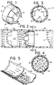
- FIG. 1 is an isometric view of an flow tab array.
- FIG. 2 is a sectional view of a bounding vessel having a fluid flowing through the flow tab array of FIG. 1.
- FIG. 3 is a sectional view of the flow tab array taken along the line 3-3 of FIG. 2.
- FIG. 4 is the same sectional view of the flow tab array of FIG. 3 looking downstream with flow direction arrows.
- FIG. 5 is a sectional view of a bounding vessel having a curvilinear interior surface adjacent to which a single tab of the tab array is shown with flow direction arrows indicating generated vortices.
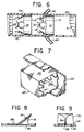
- FIG. 6 is a sectional view of a bounding vessel having a fluid flow flowing through two flow tab arrays of FIG. 1 with additional fluid injected into the flow intermediate between each of the tab arrays from opposing sides of the boundary vessel.
- FIG. 7 is a partially cutaway perspective view of an alternate embodiment of the tab array inserted in a rectangular cross-sectional boundary vessel.
- FIG. 8 is a side view of a single tab attached to the interior surface of a boundary vessel.
- FIG. 9 is a downstream view of a single tab attached to the interior surface of a boundary vessel.
- FIG. 10 is a schematic illustration showing an idealized generation of oppositely rotating, streamwise and hairpin vortices.
- FIGS. 11A-11C show the construction of a representative tab and tab array for the purpose of explaining various dimensional relationships.
-
- There is shown in FIG. 1 one embodiment of a
tab array 10 maintained in its uniformly spaced apart relationship by acollar 12 fit inside and immediately adjacent to the interior wall of a fluid containment and transport vessel, e.g. a pipe. Each of the tabs are arranged about the periphery of thecollar 12 and are attached thereto. Thetabs collar 12 when inserted into a fluid transporting vessel. Thetabs - The
tab array 10 can be inserted into a fluid containment and transport vessel such as thepipe 22 in FIGs. 2 and 3. Thecollar 12 of thetab array 10 may be affixed to the interior surface of thepipe 22 by any presently known adhesive, which does not react with the fluid, or by pressure fit of the expansion of thecollar 12 against the interior of the pipe surface. The adhesion of the pressure fit holds thetab array 10 in a perpendicular position to the direction of the fluid flow. The fluid in thepipe 22 of FIG. 2 fills the pipe and is flowing from right to left. At the right side of the section of thepipe 22 the turbulent flow is depicted by velocity profile A. Velocity profile A indicates that the flow is of a non-uniform rate as measured at a preselected point along the length of the section ofpipe 22; the flow at the top of thepipe 22 being greater then the flow at the bottom of thepipe 22. Although, the example of a flow used to describe the invention is a turbulent flow, the method can be used just as well for laminar and transitional flows. - Interposed into the non-uniform turbulent flow is the
tab array 10. As the fluid reaches the tabs 141 16, 18, 20, spaced and constructed so as to be placed in the main path of the flow, the fluid is forced to flow between and around each of the tabs as follows. The fluid is deflected up along the proximal surface of a tab creating an increase in pressure along said face and a decrease in pressure along the distal face of the tab. The fluid, as depicted by the flow direction arrows or streamlines in FIG. 2, flows outward, in relation to the tab, around the sides and outer tips of the tab. This is a result of the fluid flowing from the area of increased pressure on the proximal face of the tab to the area of decreased pressure on the distal face of the tab. The flow around thetabs - A pair of oppositely rotating, flanking tip vortices are generated by each
tab - Fig. 10 shows two
tabs flat bounding surface 21. The main fluid flow is shown by thearrows 23. As the fluid, which may be a liquid or a gas passes over thetabs tab 14, and vortices 16A and 16B are formed bytab 16. Each pair of vortices 14A, 14B or 16A, 16B constitutes a pair of oppositely rotating, flanking vortices with the axes of rotation extending generally in the flow direction as represented by thearrows 23. The sense of rotation of the vortices in Fig. 10 is represented by the adjacent arrows (unnumbered). - As indicated above, these streamwise vortices 14A, 14B and 16A, 16B do not remain in a stable configuration due to the strong interaction between the adjacent counter-rotating streamwise vortices. This interaction rapidly destabilizes the streamwise vortices 14A, 14B and 16A, 16B such that a spanwise "connection" develops between the counter rotating streamwise vortices 14A, 14B or 16A, 16B. These connections between the streamwise vortices rapidly create what appear as a continuous progression of arch-shaped vortices 14C and 16c, respectively. Such arch-shaped vortices are commonly referred to as horseshoe or hairpin vortices and are referred to hereinafter as hairpin vortices.
- As heretofore described. when an organized set of ramped tabs. e.g., the
tab array 10, is employed, the vortices generated by the tabs dramatically increase the cross-stream movement of the fluid. This increase in cross-stream movement also increases the uniformity, or homogeneity, of the fluid velocity distribution. By comparing the unmodified fluid velocity (velocity profile A) with the fluid velocity after having passed through a single tab array (velocity profile B), it can be readily seen that thetab array 10 creates a much more uniform fluid velocity as the fluid flows through the containment and transport vessel. Adding an additional tab array 110 (shown in phantom), withtabs tab arrays - In addition to affecting the uniformity of the fluid velocity across the containment and transport vessel, the tab array also promotes the transfer or exchange of thermal energy within the fluid and between the fluid and a bounding surface, for example, the containment and transport vessel. The organized set of ramped tabs creates a cross-stream intermingling of the fluid which causes the rapid and continued movement of said fluid from the center of the vessel to the areas adjacent the walls of the vessel and back to the center. Thus, a rapid exchange of thermal energy can be achieved by use of the organized ramped tab array to equalize the temperature of the fluid and/or to heat or cool the fluid more quickly as it passes through a temperature controlled section of the containment and transport vessel.
- The oppositely rotating, flanking vortices which are created thereby dramatically increases the cross-stream movement of fluid such that the temperature difference between the boundary surface and the fluid adjacent thereto will be significantly increased. Hence, the transfer of thermal energy to or from the fluid will be proportionately increased. The rapid and continued movement of fluid to and from the bounding surface and the center of the vessel assures the greatest instantaneous temperature difference between the fluid and the boundary surface. Therefore, the exchange of thermal energy will remain at a higher level than for naturally occurring processes and will continue at that level until an equilibrium condition is reached.
- This same process can be used and/or applied to the mixing or transfer of species to or away from a bounding surface, for example of a containment and transport vessel. Again, the rapid and continued movement of fluid to and from the bounding surface and the center of the vessel assures the greatest instantaneous concentration difference between the fluid at the center of the vessel and the fluid at the boundary surface. Therefore, the mixing of species will remain at a higher level than for naturally occurring processes and will continue at that level until an equilibrium condition is reached. An example of this type of exchange process would be the drying of a surface by airflow over the surface.
- Experiments performed with the
tab array 10 have indicated that the unique orientation and spacing of thetabs tab arrays tabs tab array 10 slope away from the main streamwise flow direction, the tabs are self-cleaning and non-plugging. Also, the tip vortices generated by thetabs tabs - Referring now to Figs. 3 and 4, the
tab array 10 is shown looking downstream. Thetabs tab array 10 at equally or uniformly spaced locations. In the case of the present example, four tabs are used which are located about thecollar 12 of thetab array 10 with their centers spaced 90° apart. This organized series oftabs collar 12 along the same circumferential line about the collar. As previously described, thetabs tabs tabs collar 12. The physical size of the tab will vary in direct proportion to both the shape and size of the containment and transport vessel, and the number of tabs placed about the internal periphery of said vessel. - Although the shape of the tabs may vary from square to rectangular or approach the shape of a trapezoid, the lengthwise dimension of the tab, in the direction of the main streamwise flow, is preferred not to exceed twice the width of the tab. As can be observed from the drawings, the presently preferred shape of a tab is that of a trapezoid having its bases substantially approach the measurement of its altitude such that the parallelogram is almost square in shape. For this particular embodiment the approximate dimensions are: the internal diameter of the
pipe 22 is 76,2mm (3 inches), the tab length is 25,4mm (1 inch), and the base width of the tab is 25,4mm (1 inch) tapering at the top to 15,9mm (5/8 inch). - Fig. 4 shows the flow direction of the tip vortices as they are generated by the
tabs tabs pipe 22, and outward toward the boundary surface of the pipe. Although not shown in Figs. 4 and 5, hairpin vortices as shown in Fig. 10, are also generated in a conduit such aspipe 22. It is the combination of the streamwise, oppositely rotating vortices and the arcing hairpin vortices that is responsible for the improvement in uniformity of the streamwise velocity profile and equalization of properties in the fluid and in the flow. - Referring now to Fig. 5, the generated tip vortices can be seen with greater clarity. Taking a single tab,
tab 18, which is oriented along the bottom of the containment and transport vessel, e.g. thepipe 22, the particular direction of fluid flow can be seen without confusing any particular flow direction arrow or streamline with neighboring streamlines. The main streamwise flow is shown by the flow direction arrows located along the inside of thecollar 12. As the flow strikes the base of thetab 18 it is deflected up the angled incline creating a pressure differential between the proximal face of the tab and the distal face of the tab (the face of the tab facing away from the main flow). The fluid flows up the proximal face of theinclined tab 18 and over the opposite edges and tips thereof. Once over the edges, the fluid flows underneath thetab 18 and across the distal face until it meets the opposing fluid flowing from the opposite edge of the tab at approximately the center of thetab 18. Each of the flows reverses its direction as it meets the opposing flow. While this is occurring, the fluid still retains a streamwise flow direction which creates the tip vortices by repeated meetings of the flows from either edge of thetab 18. Hence, the alternating rotations of the tip vortices are generated and the cross-stream mixing occurs along the streamwise direction of the main flow. - This flow reversal requires a minimum distance to complete the rotation, or axial revolution, begun as the fluid flows over the opposite edges of the tab. For this reason a tab shape, such as a triangle, is not desired because complete revolution would not be attainable near the forward apex of the triangle. The complete axial revolution promotes the equalization of the various properties of the fluid and the flow in a much shorter distance than experienced with prior static mixing or flow conditioning devices, or with natural mixing.
- A rectangular containment and transport vessel, a
duct 24, rather than around pipe 22, is shown in FIG. 7.Rectangular ducts 24 are normally used to contain and transport fluids in their gaseous states, but can be used for fluids in their liquid states. Atab array 26 configured with a rectangularly shapedcollar 28 to fit within theduct 24 will promote cross-stream mixing of a gas, i.e. heated or cooled air, using identically configured and arranged tabs. The tabs are uniformly spaced along the periphery of the downstream end of thecollar 28 and inclined in the direction of the flow at an acute angle within the range between 10° and 45°. Similar to the case of thetab array 10 placed within a circular bounding surface, thetab array 26 placed within a rectangular bounding surface will generate alternating rotation streamwise vortices and hairpin vortices which promote vigorous cross-stream mixing and equalization of the properties of the fluid and the flow over a much shorter distance than experienced with prior static mixing or flow conditioning devices, or with natural mixing. It may also be used an open conduit or containment and transport vessel, creating cross-stream mixing within the fluid. - Individual tabs can be arranged about the bounding surface. Referring to FIGs. 8 and 9, a
tab 30 is shown inclined inward from a boundingsurface 32 at an acute angle in the preferred range between 10° and 45°. Thetab 30 is supported by abase member 34 and maintained at the desired predetermined angular relationship to the boundingsurface 32 by asupport member 36. The lower edge of thesupport member 36 has aflange 38 which may also extend along the underside of thebase member 34 for securing thetab 30 to the boundingsurface 32. A slot in the boundingsurface 32 is configured to receive theflange 38 such that theflange 38 is oriented parallel to the main streamwise flow direction of the fluid. The proximal face of thetab 30 is oriented in a transverse or perpendicular direction to said flow. Theflange 38 may be secured within the slot by pressure fit and/or with the assistance of an adhesive which will not react with the fluid. Additionally, theflange 38 may be omitted from the basic structure and thebase member 34 and thesupport member 36 welded or adhesively affixed directly to the interior surface of a containment and transport vessel. - Several tabs, such as
tab 30, can be placed in slots provided for them at locations spaced about the interior of the boundingsurface 32. Each of the slots will be oriented in parallel relation to the others. A series of slots may be placed about the interior of a bounding surface to accommodate different numbers of tabs at uniform, or non-uniform, spacings. Thus, several configurations of tab arrays may be created in a single bounding surface by the manipulation of the tabs from location to location, e.g. three, four, six, or eight tabs may be attached without having to replace a section of the containment and transport vessel or purchase a specially configured tab array. For example, the tab array may comprise two or more tabs located along the bounding surface below the fluid flow level in an unfilled or open conduit to promote cross-stream mixing. Another configuration may comprise six uniformly spaced apart tabs located along the bounding surface in a filled conduit. Either spacing or arrangement will promote cross-stream mixing equally well. - Referring now to FIG. 6, there is shown a fluid containment and
transport vessel 22 having twotab arrays tab arrays - The
tab arrays pipe 22. Immediately downstream and beneath two of thetabs tab array 10, each of twonozzles pipe 22 for mixing with the first fluid. (Thenozzles pipe 22 at points beneath thetabs second tab array 110, pass around thetabs pipe 22 indicates an almost complete uniformity of velocity across the pipe. The introduction of a second fluid at another location between the twotab arrays tab array 110. The introduction of the second fluid beneath thetabs - Using multiple rows of tab arrays will further increase the intermingling and cross-stream mixing of the main flow. In line or staggered rows will work equally effectively. Further, increasing the number of rows of tab arrays will increase the amount of mixing accomplished by the tabs.
- The tab arrays disclosed herein are particularly useful for, but not limited to, the development of uniform flow velocity distributions immediately upstream of the measurement of the flow with a flow meter, the uniform mixing of two different species in a flowing fluid, the increased transfer of thermal energy to and/or from a flowing fluid at the bounding surface, and the improved drying of surfaces using flowing fluids, among others. The tab array design is particularly simple to construct and characterized by its low cost of operation and maintenance. Because the static mixer is configured to promote a "natural" mixing pattern, the redirection of momentum and kinetic energy in the flow results in a maximised intermingling of the fluid and a minimized loss of pumping energy. The end result achieved is a minimum pressure loss and significant energy savings relative to existing static mixers.
- As mentioned above, the method is useful in mixing gases and liquids; moreover, it can be applied with a closed bounding surface (e.g., a pipe) or a bounding surface which is not closed (e.g., a flat surface in which the flow of air is used to effect drying). An example of such an application is in convective drying ovens where fruits and other food products are dried by heated air gassing over holding trays.
- Experiments have established effective and optimal ranges of various dimensional parameters. These ranges are set forth below with reference to Figs. 11A, 11B and 11C with the dimensions being shown in these drawings. Figs. 11A and 11B are top and side views, respectively, of a single tab, generally in the shape of a trapezoid, intended for use in a circular pipe. Fig. 11C is a top view of an array showing two rows of tab arrays spaced by the distance Ls. Two tabs in each array are illustrated.
- The values given in the following table are based on experimental data except for the values which appear in parentheses. Those ranges appearing in parentheses are not based on experiments but are instead theoretical. The values given apply to any surface with the exception of tab height (h) which is indicated as a fraction of the pipe diameter in the case of a circular conduit. For other surfaces, the height is a function of length L and elevation angle
PARAMETER EFFECTIVE RANGE OPTIMAL VALUE OR RANGE Ratio of Lenth,L, to Width, W1. 0.5 ≤ L/W1 ≤ 3 1 ≤ L/W1 ≤ 2 Width at base, W1. Will depend on the number of tabs and spacing (see below) Taper angle, -10° ≤ 30° 0° ≤ 20° Width ratio, W2/W1 0.3 ≤ W2/W1 ≤ 1.2 0.6 ≤ W/2/W1 ≤ 1.1 Tab end shape (Probably square or slightly rounded corners) Elevation angle, 10° ≤ ≤ 45° 20° ≤ ≤ 35° Tab height, h 0.1 ≤ h/D ≤ 9,3 (0.16 ≤ h/D ≤ 0.24) Spacing between tabs of an array: Width ratio, Ws/W1 0.5 ≤ Ws/W1 ≤ 2 Spacing between tab arrays: Length ratio, Ls/W1 (0.5 ≤ Ls/W1 ≤ 6) (1 ≤ Ls/W1 ≤ 2) Method of arrangment of multiple arrays (row) of tabs in-line or staggered in-line - The number of tabs in a single array (row) of tabs in a circular pipe may depend on the tab geometry and it is contemplated that anywhere from two to ten tabs can be used in a single row with four tabs being optimal at least for a geometrically symmetric tab in which the length L is equal to the width W1.
- Tests have been conducted for Reynolds numbers as low as 1000. These tests have not indicated any significant change in the optical geometric ranges given above as a function of the Reynolds numbers.
Claims (4)
- A method for producing cross-stream mixing in a fluid flow (23), flowing with a main stream direction in a fluid containment and transport vessel (22,24) having a bounding surface (21,32),
characterized bydirecting a fluid flow with Reynolds numbers of 1,000 or more of one or more fluids comprising a liquid and/or a gas along at least one ramped tab (14,16,18,20,114, 116,118,120,30) of one or more tabs or one or more tab arrays (10,110,26), each of said tabs being of rectangular or square or inwardly tapered shape and being flat and having a flat proximal face facing toward the fluid flow and extending upwardly from the bounding surface (21,32) at an acute angle (β) between approx. 10 and 45°, and having a distal face facing away from the fluid flow,the fluid flow being maintained at a sufficient rate and at a sufficient velocity to create increased pressure along the proximal face and decreased pressure along the distal face of the tab and to flow from an area of increased pressure on the proximal face of the tab around the side edges and the outer tips of the tab for forming at least one pair of oppositely rotating flanking tip vortices (14A,14B,16A,16B) in said fluid flow (23), the tip vortices having their axes of rotation substantially in the stream-wise direction of the fluid flow (23),the ratio (L/W) of the length (L) to the width (W) of the rectangular or square tab or the ratio of (L/W1) of the length (L) to the base width (W1) of the inwardly tapered tab is between 0.5 and 3.0, andthe ratio (W2/W1) of the end width (W2) to the base width (W1) of the tapered tab is between 0.3 and 1.2. - Method as in claim 1, characterised in that said fluid containment and transport vessel (22) is formed as a circular conduit with a pipe diameter (D), and that the ratio (h/D) of the height (h) of the tab end above the bounding surface (21) to the pipe diameter (D) is between 0, 1 and 0, 3.
- Method as in claim 1, characterised in that the ratio (Ws/W) of a lateral spacing (Ws) between adjacent tabs to the width (W) of the rectangular or square tab, or the ratio (Ws/W1) of a lateral spacing (Ws) between adjacent tapered tabs to the base width (W1) of each tapered tab is between 0,5 or 2,0.
- Method as in claim 1, characterised in that the ratio (LS/W1) of a streamwise spacing (LS) between subsequent tapered tabs to the base width (W1) of each tapered tab is between 0, 5 and 6, 0, respectively.
Applications Claiming Priority (5)
| Application Number | Priority Date | Filing Date | Title |
|---|---|---|---|
| US07/224,690 US4981368A (en) | 1988-07-27 | 1988-07-27 | Static fluid flow mixing method |
| US224690 | 1988-07-27 | ||
| US07/360,037 US4929088A (en) | 1988-07-27 | 1989-06-06 | Static fluid flow mixing apparatus |
| US360037 | 1989-06-06 | ||
| PCT/US1989/003248 WO1990000929A1 (en) | 1988-07-27 | 1989-07-27 | Static fluid flow mixing apparatus |
Publications (3)
| Publication Number | Publication Date |
|---|---|
| EP0430973A1 EP0430973A1 (en) | 1991-06-12 |
| EP0430973A4 EP0430973A4 (en) | 1991-12-11 |
| EP0430973B1 true EP0430973B1 (en) | 1999-03-10 |
Family
ID=26918947
Family Applications (1)
| Application Number | Title | Priority Date | Filing Date |
|---|---|---|---|
| EP89908751A Expired - Lifetime EP0430973B1 (en) | 1988-07-27 | 1989-07-27 | Static fluid flow mixing apparatus |
Country Status (6)
| Country | Link |
|---|---|
| US (1) | US4929088A (en) |
| EP (1) | EP0430973B1 (en) |
| AT (1) | ATE177342T1 (en) |
| AU (1) | AU635214B2 (en) |
| DE (1) | DE68928945T2 (en) |
| WO (1) | WO1990000929A1 (en) |
Cited By (2)
| Publication number | Priority date | Publication date | Assignee | Title |
|---|---|---|---|---|
| CN103032138A (en) * | 2011-09-28 | 2013-04-10 | J·埃贝斯佩歇合资公司 | Mixing and/or evaporating device |
| CN105386830A (en) * | 2014-08-21 | 2016-03-09 | 通用汽车环球科技运作有限责任公司 | Mixer for short mixing lengths |
Families Citing this family (99)
| Publication number | Priority date | Publication date | Assignee | Title |
|---|---|---|---|---|
| US5425580A (en) * | 1990-12-28 | 1995-06-20 | Byk Gulden Lomberg Chemische Fabrik Gmbh | Dosage form for micro-bubble echo contrast agents |
| DE4123161A1 (en) * | 1991-07-12 | 1993-01-14 | Siemens Ag | STATIC MIXER |
| EP0526393B1 (en) * | 1991-07-30 | 1996-08-28 | Sulzer Chemtech AG | mixing-in device |
| FR2683003B1 (en) * | 1991-10-25 | 1995-02-17 | Schlumberger Ind Sa | FLOW RECTIFIER. |
| WO1994013392A1 (en) * | 1991-11-29 | 1994-06-23 | Ki N Proizv Ob | Method and device for producing a free dispersion system |
| EP0546989B1 (en) * | 1991-12-10 | 1995-11-15 | Sulzer Chemtech AG | Static mixing element with guiding faces |
| US5266343A (en) * | 1992-02-14 | 1993-11-30 | Stauffer John E | Pasteurization process for dairy products |
| DE59401295D1 (en) * | 1993-04-08 | 1997-01-30 | Abb Management Ag | Mixing chamber |
| US5445799A (en) * | 1993-10-20 | 1995-08-29 | Mccants; Malcolm T. | Apparatus and method for thermocracking a fluid |
| US5454640A (en) * | 1994-01-28 | 1995-10-03 | Welker; Robert H. | Flow diffuser for redistributing stratified liquids in a pipeline |
| US5492655A (en) * | 1994-05-31 | 1996-02-20 | Schuller International, Inc. | Air/liquid static foam generator |
| US5480589A (en) * | 1994-09-27 | 1996-01-02 | Nordson Corporation | Method and apparatus for producing closed cell foam |
| ATE189620T1 (en) * | 1995-05-09 | 2000-02-15 | Labatt Brewing Co Ltd | STATIC DEVICE FOR FLOW MIXING OF FLUIDS |
| US5696380A (en) * | 1995-05-09 | 1997-12-09 | Labatt Brewing Company Limited | Flow-through photo-chemical reactor |
| US5730416A (en) * | 1995-06-07 | 1998-03-24 | Welker Engineering Company | Method and apparatus for quieting turbulence in a gas flow line valve |
| DE59610627D1 (en) * | 1996-04-12 | 2003-09-04 | Sulzer Chemtech Ag Winterthur | Mixing tube for low-viscosity fluids |
| US5727398A (en) * | 1996-07-25 | 1998-03-17 | Phillippe; Gary E. | Refrigerant agitation apparatus |
| US6015229A (en) * | 1997-09-19 | 2000-01-18 | Calgon Carbon Corporation | Method and apparatus for improved mixing in fluids |
| DE19755905C1 (en) | 1997-12-16 | 1999-05-12 | Binder Engineering Gmbh | Fluid flow rectifier module for aligning flow in pipe |
| US5931771A (en) * | 1997-12-24 | 1999-08-03 | Kozyuk; Oleg V. | Method and apparatus for producing ultra-thin emulsions and dispersions |
| US5971601A (en) * | 1998-02-06 | 1999-10-26 | Kozyuk; Oleg Vyacheslavovich | Method and apparatus of producing liquid disperse systems |
| US5971603A (en) * | 1998-03-06 | 1999-10-26 | The Madison Group: Polymer Processing Research Corp. | Static mixer head |
| FI104384B (en) * | 1998-06-05 | 2000-01-14 | Valmet Corp | Apparatus and Method for Mixing Freshwater and Fresh Mass in a Post-Wastewater Canal |
| US6314721B1 (en) | 1998-09-04 | 2001-11-13 | United Technologies Corporation | Tabbed nozzle for jet noise suppression |
| US6487848B2 (en) | 1998-11-06 | 2002-12-03 | United Technologies Corporation | Gas turbine engine jet noise suppressor |
| US6036356A (en) * | 1998-12-23 | 2000-03-14 | United Microelectronics Corp. | In-situ slurry mixing apparatus |
| CA2370778C (en) | 1999-04-19 | 2006-09-26 | Koch-Glitsch, Inc. | Vortex static mixer and method employing same |
| US6279611B2 (en) * | 1999-05-10 | 2001-08-28 | Hideto Uematsu | Apparatus for generating microbubbles while mixing an additive fluid with a mainstream liquid |
| US6439267B2 (en) | 1999-07-23 | 2002-08-27 | Welker Engineering Company | Adjustable flow diffuser |
| US6289934B1 (en) | 1999-07-23 | 2001-09-18 | Welker Engineering Company | Flow diffuser |
| FR2807336B1 (en) * | 2000-04-07 | 2002-12-13 | Pour Le Dev De L Antipollution | STATIC MIXER |
| CA2343561C (en) * | 2000-05-08 | 2004-11-30 | Sulzer Chemtech Ag | Mixing element for a flange transition in a pipeline |
| EP1166861B1 (en) * | 2000-06-19 | 2003-03-26 | Balcke-Dürr Energietechnik GmbH | Mixer for mixing at least two gas streams or other Newtonian liquids |
| US6886973B2 (en) * | 2001-01-03 | 2005-05-03 | Basic Resources, Inc. | Gas stream vortex mixing system |
| US20020097634A1 (en) * | 2001-01-24 | 2002-07-25 | Pilkington Phyllis Heather | Gas lift bio-reactor designs |
| US20030058737A1 (en) * | 2001-09-25 | 2003-03-27 | Berry Jonathan Dwight | Mixer/flow conditioner |
| DE50209465D1 (en) * | 2001-10-16 | 2007-03-29 | Sulzer Chemtech Ag | Pipe section with a feed point for an additive |
| US6935371B2 (en) * | 2002-02-22 | 2005-08-30 | Dresser, Inc. | High capacity globe valve |
| US6807986B2 (en) * | 2002-03-22 | 2004-10-26 | Dresser, Inc. | Noise reduction device for fluid flow systems |
| US7264394B1 (en) | 2002-06-10 | 2007-09-04 | Inflowsion L.L.C. | Static device and method of making |
| US7041218B1 (en) | 2002-06-10 | 2006-05-09 | Inflowsion, L.L.C. | Static device and method of making |
| US7045060B1 (en) | 2002-12-05 | 2006-05-16 | Inflowsion, L.L.C. | Apparatus and method for treating a liquid |
| US7108838B2 (en) | 2003-10-30 | 2006-09-19 | Conocophillips Company | Feed mixer for a partial oxidation reactor |
| US20050094482A1 (en) * | 2003-10-31 | 2005-05-05 | Nordson Corporation | Method and apparatus for producing closed cell foam |
| CA2616997C (en) * | 2004-09-13 | 2014-12-23 | Oriel Therapeutics, Inc. | Dry powder inhalers that inhibit agglomeration, related devices and methods |
| US7383850B2 (en) | 2005-01-18 | 2008-06-10 | Peerless Mfg. Co. | Reagent injection grid |
| JP4989062B2 (en) * | 2005-04-28 | 2012-08-01 | バブコック日立株式会社 | Fluid mixing device |
| ATE492790T1 (en) * | 2005-10-14 | 2011-01-15 | Kamstrup As | ULTRASONIC FLOW METER WITH FLOW MIXER |
| AU2006315077B2 (en) * | 2005-11-15 | 2012-02-23 | Technological Resources Pty Limited | A device for modifying fluid flow through a conduit |
| CA2832673A1 (en) * | 2005-11-15 | 2007-05-24 | Peter Nicolay | A device for modifying fluid flow through a conduit |
| DE102007005497A1 (en) * | 2007-01-30 | 2008-07-31 | J. Eberspächer GmbH & Co. KG | Exhaust gas system for internal-combustion engine of motor vehicle, has exhaust gas line for discharging exhaust gas, and mixing and/or vaporizing device integrally formed at end section of exhaust gas pipe |
| DE102007019878A1 (en) * | 2007-04-25 | 2008-11-06 | J. Eberspächer GmbH & Co. KG | Mixing and / or evaporating device and associated production method |
| DE102007028449A1 (en) * | 2007-04-25 | 2008-10-30 | J. Eberspächer GmbH & Co. KG | Mixing and / or evaporating device and associated production method |
| US8696192B2 (en) | 2007-05-10 | 2014-04-15 | Fluid-Quip, Inc. | Multiple helical vortex baffle |
| WO2009008450A1 (en) * | 2007-07-11 | 2009-01-15 | Toyota Jidosha Kabushiki Kaisha | Exhaust emission purifier of internal combustion engine |
| DE102008013224A1 (en) | 2008-03-07 | 2009-09-10 | Endress + Hauser Flowtec Ag | Measuring system for determining and/or monitoring flow of measuring medium through measuring tube, has measuring tube, where signal path runs and partly lies in partial volume of tube on plane |
| US9353585B2 (en) * | 2008-03-07 | 2016-05-31 | Halliburton Energy Services, Inc. | On-the-fly acid blender with sampling equipment |
| US9095827B2 (en) | 2008-04-21 | 2015-08-04 | Tenneco Automotive Operating Company Inc. | Exhaust gas flow mixer |
| US8939638B2 (en) | 2008-04-21 | 2015-01-27 | Tenneco Automotive Operating Company Inc. | Method for mixing an exhaust gas flow |
| US20100074814A1 (en) * | 2008-09-25 | 2010-03-25 | Cummins Filtration Ip Inc. | Reductant decomposition mixer and method for making the same |
| US8714936B2 (en) | 2009-07-02 | 2014-05-06 | Exxonmobil Upstream Research Company | Fluid sealing elements and related methods |
| CA2763511C (en) | 2009-07-02 | 2015-10-13 | Exxonmobil Upstream Research Company | Plunger lift systems and methods |
| US20110048564A1 (en) | 2009-08-25 | 2011-03-03 | Fluid Components International Llc | Fluid flow conditioner |
| US8517598B1 (en) * | 2009-09-22 | 2013-08-27 | The United States Of America As Represented By The Secretary Of The Navy | Removable baffles for mixing vessel |
| WO2011073717A1 (en) * | 2009-12-18 | 2011-06-23 | Renault Trucks | Mixing system for an exhaust gases after-treatment arrangement |
| JOP20200123A1 (en) | 2010-01-20 | 2017-06-16 | Mecs Inc | Energy recovery in manufacture of sulfuric acid |
| US20110174408A1 (en) * | 2010-01-21 | 2011-07-21 | Fluid Components International Llc | Flow mixer and conditioner |
| US9010994B2 (en) * | 2010-01-21 | 2015-04-21 | Fluid Components International Llc | Flow mixer and conditioner |
| US8936392B2 (en) * | 2010-06-15 | 2015-01-20 | Ecosphere Technologies, Inc. | Hydrodynamic cavitation device |
| HUE036624T2 (en) * | 2010-09-28 | 2018-07-30 | Dow Global Technologies Llc | Reactive flow static mixer with cross-flow obstructions and mixing method |
| US9051724B2 (en) * | 2011-04-12 | 2015-06-09 | Hydro International Plc | Flow regulating device |
| DE102011112028B4 (en) * | 2011-08-31 | 2021-07-01 | Diehl Metering Gmbh | Ultrasonic meter |
| DE102011083637B4 (en) * | 2011-09-28 | 2016-04-14 | Eberspächer Exhaust Technology GmbH & Co. KG | Mixing and / or evaporation device |
| DE102012200170A1 (en) | 2012-01-06 | 2013-07-11 | Continental Automotive Gmbh | mixing valve |
| US9649604B2 (en) * | 2012-05-10 | 2017-05-16 | General Electric Technology Gmbh | Injector grid with two stage mixer |
| US8755682B2 (en) | 2012-07-18 | 2014-06-17 | Trebor International | Mixing header for fluid heater |
| US9737835B2 (en) * | 2012-07-31 | 2017-08-22 | Cummins Filtration Ip, Inc. | Methods and apparatuses for separating liquid particles from a gas-liquid stream |
| DE102012016423B3 (en) * | 2012-08-21 | 2014-02-27 | Eberspächer Exhaust Technology GmbH & Co. KG | Exhaust system with mixing and or evaporation device |
| US20140102483A1 (en) * | 2012-10-12 | 2014-04-17 | Caterpillar Inc. | System and method to remove debris from a chamber |
| US9504947B2 (en) | 2012-11-13 | 2016-11-29 | Cummins Filtration Ip, Inc. | Air filter assemblies and carrier frames having vortex-generating flow guide |
| TW201437146A (en) | 2012-12-18 | 2014-10-01 | Invista Tech Sarl | Processes for producing hydrogen cyanide using static mixer |
| EP2971802B1 (en) * | 2013-03-15 | 2018-09-05 | Institute of Science and Technology Austria | Eliminating turbulence in wall-bounded flows by distorting the flow velocity distribution in a direction perpendicular to the wall |
| CA2902562C (en) | 2013-03-15 | 2022-01-04 | Ernesto Vera-Castaneda | Recovery of sulfur trioxide heat of absorption |
| TWM458497U (en) * | 2013-04-08 | 2013-08-01 | guo-zhen Cai | Water hammer cancellation device |
| EP2796188B1 (en) * | 2013-04-25 | 2016-04-06 | Sansox Oy | Apparatus for mixing additive with liquid |
| US9783309B2 (en) * | 2013-07-16 | 2017-10-10 | The Boeing Company | Methods and device for mixing airflows in environmental control systems |
| US20150040547A1 (en) * | 2013-08-08 | 2015-02-12 | Tenneco Automotive Operating Company Inc. | Mirrored Two-Stage Mixer |
| DE112014005413B4 (en) * | 2013-11-26 | 2019-08-29 | Tenneco Automotive Operating Company Inc. | Exhaust flow mixer |
| CA2847632A1 (en) * | 2014-01-09 | 2015-07-09 | Charles Garner | Polymer static mixer |
| US9718037B2 (en) * | 2014-12-17 | 2017-08-01 | Caterpillar Inc. | Mixing system for aftertreatment system |
| US9534525B2 (en) | 2015-05-27 | 2017-01-03 | Tenneco Automotive Operating Company Inc. | Mixer assembly for exhaust aftertreatment system |
| DE112017002620B4 (en) | 2016-05-23 | 2023-01-26 | Mitsubishi Heavy Industries, Ltd. | combustor and gas turbine |
| US10662746B2 (en) | 2016-06-30 | 2020-05-26 | Exxonmobil Upstream Research Company | Plunger sleeve for artificial lift systems |
| GB201806020D0 (en) * | 2018-02-23 | 2018-05-30 | Rolls Royce | Conduit |
| US10737227B2 (en) | 2018-09-25 | 2020-08-11 | Westfall Manufacturing Company | Static mixer with curved fins |
| US11028755B2 (en) * | 2019-03-20 | 2021-06-08 | Caterpillar Inc. | Rotational exhaust flow control for diesel exhaust fluid injection |
| US11448160B2 (en) | 2019-09-23 | 2022-09-20 | General Electric Company | High temperature gradient gas mixer |
| US11285448B1 (en) * | 2021-04-12 | 2022-03-29 | William J. Lund | Static mixer inserts and static mixers incorporating same |
| EP4303436A1 (en) * | 2022-07-04 | 2024-01-10 | Wobben Properties GmbH | Wind turbine blade rotor blade and wind turbine |
Family Cites Families (22)
| Publication number | Priority date | Publication date | Assignee | Title |
|---|---|---|---|---|
| FR606324A (en) * | 1925-09-15 | 1926-06-11 | Mixing devices | |
| BE578478A (en) * | 1958-07-08 | 1900-01-01 | ||
| US3337194A (en) * | 1965-08-09 | 1967-08-22 | Phillips Petroleum Co | In-line blender |
| NL6815942A (en) * | 1967-11-09 | 1969-05-13 | ||
| US3620506A (en) * | 1970-07-07 | 1971-11-16 | Fmc Corp | Fluid-mixing device |
| US3652061A (en) * | 1971-03-04 | 1972-03-28 | Dow Chemical Co | Interfacial surface generator and method of preparation thereof |
| US3733057A (en) * | 1971-09-07 | 1973-05-15 | Cons Paper Inc | In-line fluid mixer |
| US4034965A (en) * | 1973-12-27 | 1977-07-12 | Komax Systems, Inc. | Material distributing and mixing apparatus |
| US4072296A (en) * | 1975-07-16 | 1978-02-07 | Doom Lewis G | Motionless mixer |
| US4136720A (en) * | 1976-03-08 | 1979-01-30 | Phillips Petroleum Company | Production of a marbled product |
| US4112520A (en) * | 1976-03-25 | 1978-09-05 | Oscar Patton Gilmore | Static mixer |
| US4093188A (en) * | 1977-01-21 | 1978-06-06 | Horner Terry A | Static mixer and method of mixing fluids |
| US4179222A (en) * | 1978-01-11 | 1979-12-18 | Systematix Controls, Inc. | Flow turbulence generating and mixing device |
| US4314974A (en) * | 1979-04-30 | 1982-02-09 | Chemineer, Inc. | Solvent extraction method using static mixers |
| HU179455B (en) * | 1979-07-16 | 1982-10-28 | Energiagazdalkodasi Intezet | Ribbed device improving the heat transfer composed from sheet strips |
| DE3043239C2 (en) * | 1980-11-15 | 1985-11-28 | Balcke-Dürr AG, 4030 Ratingen | Method and device for mixing at least two fluid partial flows |
| US4363552A (en) * | 1981-03-18 | 1982-12-14 | E. I. Du Pont De Nemours And Company | Static mixer |
| DE3116557A1 (en) * | 1981-04-25 | 1982-11-11 | Basf Ag, 6700 Ludwigshafen | DEVICE FOR INVERTING AND MIXING FLOWING SUBSTANCES |
| EP0070915A1 (en) * | 1981-07-30 | 1983-02-09 | GebràDer Sulzer Aktiengesellschaft | Installation element for an apparatus for mass transfer, direct heat exchange and mixing |
| US4808007A (en) * | 1982-05-13 | 1989-02-28 | Komax Systems, Inc. | Dual viscosity mixer |
| US4600544A (en) * | 1982-11-29 | 1986-07-15 | Merix Corporation | Packing unit and method of making |
| JPS62144738A (en) * | 1985-12-20 | 1987-06-27 | Hisao Kojima | Liquid mixer |
-
1989
- 1989-06-06 US US07/360,037 patent/US4929088A/en not_active Expired - Lifetime
- 1989-07-27 DE DE68928945T patent/DE68928945T2/en not_active Expired - Fee Related
- 1989-07-27 AU AU39876/89A patent/AU635214B2/en not_active Ceased
- 1989-07-27 EP EP89908751A patent/EP0430973B1/en not_active Expired - Lifetime
- 1989-07-27 WO PCT/US1989/003248 patent/WO1990000929A1/en active IP Right Grant
- 1989-07-27 AT AT89908751T patent/ATE177342T1/en not_active IP Right Cessation
Cited By (3)
| Publication number | Priority date | Publication date | Assignee | Title |
|---|---|---|---|---|
| CN103032138A (en) * | 2011-09-28 | 2013-04-10 | J·埃贝斯佩歇合资公司 | Mixing and/or evaporating device |
| CN105386830A (en) * | 2014-08-21 | 2016-03-09 | 通用汽车环球科技运作有限责任公司 | Mixer for short mixing lengths |
| CN105386830B (en) * | 2014-08-21 | 2018-02-09 | 通用汽车环球科技运作有限责任公司 | Blender for short mixing length |
Also Published As
| Publication number | Publication date |
|---|---|
| EP0430973A4 (en) | 1991-12-11 |
| WO1990000929A1 (en) | 1990-02-08 |
| DE68928945T2 (en) | 1999-10-07 |
| EP0430973A1 (en) | 1991-06-12 |
| AU635214B2 (en) | 1993-03-18 |
| DE68928945D1 (en) | 1999-04-15 |
| AU3987689A (en) | 1990-02-19 |
| ATE177342T1 (en) | 1999-03-15 |
| US4929088A (en) | 1990-05-29 |
Similar Documents
| Publication | Publication Date | Title |
|---|---|---|
| EP0430973B1 (en) | Static fluid flow mixing apparatus | |
| US4981368A (en) | Static fluid flow mixing method | |
| KR100739523B1 (en) | Mixer and mixing method | |
| US4527903A (en) | Apparatus for uniformizing the parameters of a flow and/or for mixing together at least two individual streams which discharge into a main flow | |
| US6000841A (en) | Static fluid flow mixing apparatus | |
| US6604850B1 (en) | Vortex static mixer | |
| US4179222A (en) | Flow turbulence generating and mixing device | |
| US5664733A (en) | Fluid mixing nozzle and method | |
| US6135629A (en) | Device for stirring up gas flowing through a duct having a structural insert positioned at an acute angle to a main gas stream | |
| KR100515233B1 (en) | Arrangement for combining dissimilar streams | |
| JPS6377524A (en) | Method of mixing two or more of gas flow | |
| EP2517785A1 (en) | Baffle for a fluid conduit, and related apparatus | |
| EP2399664A1 (en) | Method for mixing dust | |
| US5803602A (en) | Fluid mixing device with vortex generators | |
| CA1142509A (en) | Static mixer tube with internal triangular element approximations to helices | |
| US3494047A (en) | Method and apparatus for carrying out physical and chemical reactions | |
| US4874249A (en) | Arrangement for continuous mixing of liquids | |
| WO1999000180A1 (en) | Multi-component static mixer and method of operation | |
| US5680884A (en) | Rectifying device | |
| US3771589A (en) | Method and apparatus for improved transfer of heat | |
| JP2021501683A (en) | Improved mixer duct and process using it | |
| JPS63194193A (en) | Heat transfer improving device | |
| US6016799A (en) | Vortex chamber for deep fryer heat exchanger | |
| JPS5827626A (en) | Apparatus for mixing fluids | |
| JPS5939176B2 (en) | fluid injection mixing device |
Legal Events
| Date | Code | Title | Description |
|---|---|---|---|
| PUAI | Public reference made under article 153(3) epc to a published international application that has entered the european phase |
Free format text: ORIGINAL CODE: 0009012 |
|
| 17P | Request for examination filed |
Effective date: 19910125 |
|
| AK | Designated contracting states |
Kind code of ref document: A1 Designated state(s): AT BE CH DE FR GB IT LI LU NL SE |
|
| A4 | Supplementary search report drawn up and despatched |
Effective date: 19911018 |
|
| AK | Designated contracting states |
Kind code of ref document: A4 Designated state(s): AT BE CH DE FR GB IT LI LU NL SE |
|
| 17Q | First examination report despatched |
Effective date: 19920928 |
|
| GRAG | Despatch of communication of intention to grant |
Free format text: ORIGINAL CODE: EPIDOS AGRA |
|
| GRAG | Despatch of communication of intention to grant |
Free format text: ORIGINAL CODE: EPIDOS AGRA |
|
| GRAH | Despatch of communication of intention to grant a patent |
Free format text: ORIGINAL CODE: EPIDOS IGRA |
|
| GRAH | Despatch of communication of intention to grant a patent |
Free format text: ORIGINAL CODE: EPIDOS IGRA |
|
| GRAA | (expected) grant |
Free format text: ORIGINAL CODE: 0009210 |
|
| AK | Designated contracting states |
Kind code of ref document: B1 Designated state(s): AT BE CH DE FR GB IT LI LU NL SE |
|
| PG25 | Lapsed in a contracting state [announced via postgrant information from national office to epo] |
Ref country code: SE Free format text: THE PATENT HAS BEEN ANNULLED BY A DECISION OF A NATIONAL AUTHORITY Effective date: 19990310 Ref country code: LI Free format text: LAPSE BECAUSE OF FAILURE TO SUBMIT A TRANSLATION OF THE DESCRIPTION OR TO PAY THE FEE WITHIN THE PRESCRIBED TIME-LIMIT Effective date: 19990310 Ref country code: CH Free format text: LAPSE BECAUSE OF FAILURE TO SUBMIT A TRANSLATION OF THE DESCRIPTION OR TO PAY THE FEE WITHIN THE PRESCRIBED TIME-LIMIT Effective date: 19990310 Ref country code: AT Free format text: LAPSE BECAUSE OF FAILURE TO SUBMIT A TRANSLATION OF THE DESCRIPTION OR TO PAY THE FEE WITHIN THE PRESCRIBED TIME-LIMIT Effective date: 19990310 |
|
| REF | Corresponds to: |
Ref document number: 177342 Country of ref document: AT Date of ref document: 19990315 Kind code of ref document: T |
|
| REG | Reference to a national code |
Ref country code: CH Ref legal event code: EP |
|
| REF | Corresponds to: |
Ref document number: 68928945 Country of ref document: DE Date of ref document: 19990415 |
|
| ET | Fr: translation filed | ||
| PG25 | Lapsed in a contracting state [announced via postgrant information from national office to epo] |
Ref country code: LU Free format text: LAPSE BECAUSE OF NON-PAYMENT OF DUE FEES Effective date: 19990727 |
|
| REG | Reference to a national code |
Ref country code: CH Ref legal event code: PL |
|
| PLBE | No opposition filed within time limit |
Free format text: ORIGINAL CODE: 0009261 |
|
| STAA | Information on the status of an ep patent application or granted ep patent |
Free format text: STATUS: NO OPPOSITION FILED WITHIN TIME LIMIT |
|
| 26N | No opposition filed | ||
| PGFP | Annual fee paid to national office [announced via postgrant information from national office to epo] |
Ref country code: DE Payment date: 20000724 Year of fee payment: 12 |
|
| PGFP | Annual fee paid to national office [announced via postgrant information from national office to epo] |
Ref country code: FR Payment date: 20000725 Year of fee payment: 12 |
|
| PGFP | Annual fee paid to national office [announced via postgrant information from national office to epo] |
Ref country code: GB Payment date: 20000726 Year of fee payment: 12 |
|
| PGFP | Annual fee paid to national office [announced via postgrant information from national office to epo] |
Ref country code: NL Payment date: 20000728 Year of fee payment: 12 |
|
| PGFP | Annual fee paid to national office [announced via postgrant information from national office to epo] |
Ref country code: BE Payment date: 20000918 Year of fee payment: 12 |
|
| PG25 | Lapsed in a contracting state [announced via postgrant information from national office to epo] |
Ref country code: GB Free format text: LAPSE BECAUSE OF NON-PAYMENT OF DUE FEES Effective date: 20010727 |
|
| PG25 | Lapsed in a contracting state [announced via postgrant information from national office to epo] |
Ref country code: BE Free format text: LAPSE BECAUSE OF NON-PAYMENT OF DUE FEES Effective date: 20010731 |
|
| BERE | Be: lapsed |
Owner name: VORTAB CORP. Effective date: 20010731 |
|
| PG25 | Lapsed in a contracting state [announced via postgrant information from national office to epo] |
Ref country code: NL Free format text: LAPSE BECAUSE OF NON-PAYMENT OF DUE FEES Effective date: 20020201 |
|
| GBPC | Gb: european patent ceased through non-payment of renewal fee |
Effective date: 20010727 |
|
| PG25 | Lapsed in a contracting state [announced via postgrant information from national office to epo] |
Ref country code: FR Free format text: LAPSE BECAUSE OF NON-PAYMENT OF DUE FEES Effective date: 20020329 |
|
| NLV4 | Nl: lapsed or anulled due to non-payment of the annual fee |
Effective date: 20020201 |
|
| PG25 | Lapsed in a contracting state [announced via postgrant information from national office to epo] |
Ref country code: DE Free format text: LAPSE BECAUSE OF NON-PAYMENT OF DUE FEES Effective date: 20020501 |
|
| REG | Reference to a national code |
Ref country code: FR Ref legal event code: ST |
|
| PG25 | Lapsed in a contracting state [announced via postgrant information from national office to epo] |
Ref country code: IT Free format text: LAPSE BECAUSE OF NON-PAYMENT OF DUE FEES Effective date: 20050727 |