EP0424057A2 - Modular ammunition packaging and feed system - Google Patents
Modular ammunition packaging and feed system Download PDFInfo
- Publication number
- EP0424057A2 EP0424057A2 EP90311243A EP90311243A EP0424057A2 EP 0424057 A2 EP0424057 A2 EP 0424057A2 EP 90311243 A EP90311243 A EP 90311243A EP 90311243 A EP90311243 A EP 90311243A EP 0424057 A2 EP0424057 A2 EP 0424057A2
- Authority
- EP
- European Patent Office
- Prior art keywords
- magazine
- ammunition
- packs
- feed system
- modular
- Prior art date
- Legal status (The legal status is an assumption and is not a legal conclusion. Google has not performed a legal analysis and makes no representation as to the accuracy of the status listed.)
- Granted
Links
Images


Classifications
-
- F—MECHANICAL ENGINEERING; LIGHTING; HEATING; WEAPONS; BLASTING
- F41—WEAPONS
- F41A—FUNCTIONAL FEATURES OR DETAILS COMMON TO BOTH SMALLARMS AND ORDNANCE, e.g. CANNONS; MOUNTINGS FOR SMALLARMS OR ORDNANCE
- F41A9/00—Feeding or loading of ammunition; Magazines; Guiding means for the extracting of cartridges
- F41A9/61—Magazines
- F41A9/64—Magazines for unbelted ammunition
- F41A9/76—Magazines having an endless-chain conveyor
-
- F—MECHANICAL ENGINEERING; LIGHTING; HEATING; WEAPONS; BLASTING
- F41—WEAPONS
- F41A—FUNCTIONAL FEATURES OR DETAILS COMMON TO BOTH SMALLARMS AND ORDNANCE, e.g. CANNONS; MOUNTINGS FOR SMALLARMS OR ORDNANCE
- F41A9/00—Feeding or loading of ammunition; Magazines; Guiding means for the extracting of cartridges
- F41A9/61—Magazines
- F41A9/63—Magazines specially adapted for releasable connection with other magazines
Definitions
- the present invention relates generally to article handling systems, and particularly to ammunition handling systems for rapid-fire guns.
- Ammunition handling systems include a container or magazine in which ammunition rounds are packaged and a feeder for withdrawing rounds from the magazine for delivery to the gun on demand and in rapid succession.
- the ammunition is packaged in the magazine either as linked or linkless (loose) ammunition.
- the rounds of linked ammunition are interconnected to form an elongated belt which is drawn from the magazine to feed rounds successively to the gun.
- the rounds are not interconnected, and thus the magazine must be interiorly equipped with a powered conveyor for transporting the loose rounds through the magazine to an exit port. Since the conveyor must move at high velocities to satisfy the rapid-fire capabilities of modern guns, absolute and continuous control of round movement throughout the magazine interior must be maintained. To achieve this, the conveyor is equipped with round carriers.uniformly distributed along its length. These carriers, with the aid of stationary magazine guide surfaces, can effectively secure the rounds to the conveyor such that they reliably follow the conveyor path through the magazine, which is typically tortuous, e.g., serpentine, to maximize packaging density.
- Reloading from a resupply of linkless ammunition involves many of the same drawbacks.
- This approach requires a rather elaborate reloading system including a loading conveyor which must be cycled in synchronism with the magazine conveyor to withdraw live rounds from a bulk storage container and a transfer mechanism for picking rounds from the loading conveyor and handing them off to the magazine conveyor.
- Having such an elaborate reloading system available at a forward area rearming position presents significant logistical problems.
- an adequate source of power to cycle both linear linkless conveyors may not be readily available.
- linear linkless ammunition feeding systems require considerable maintenance.
- a breakdown in the field invariably requires depot service, which means that the gun system served by the feed system is out of action until repairs are effected.
- An additional disadvantage of linear linkless ammunition feed systems is that the magazine is of significant weight even when empty. In airborne applications, this empty weight limits the amount of alternative armament, such as rockets or missiles, and/or auxiliary fuel tanks an aircraft can safely carry.
- an article handling system such as an ammunition feed system utilizing a modular packaging approach wherein ammunition rounds are accommodated in highly portable magazine packs or cassettes.
- Each pack includes a case equipped with a convenient carrying handle.
- Each case contains an endless linear linkless ammunition conveyor having a plurality of carriers distributed along its length for individually accommodating an ammunition round and an external drive element drivingly connected with the conveyor within.
- the ammunition packs are separately installed in plural side-by-side load positions provided by a support frame equipped with a drive mechanism including a power takeoff site aligned with each load position. Installation of an ammunition pack in a load position automatically effects driving engagement of the pack drive element with the power takeoff site thereat.
- the drive mechanism is activated to drive the magazine packs conveyors in unison. The ammunition rounds are thus routed between conveyors of adjacent magazine packs along a serpentine feed path leading to a transfer unit where they are successively handled off to an exiting gun conveyor.
- the empty ammunition packs are simply removed from their load positions and replaced with packs containing live rounds. Reloading can thus be accomplish more reliably and expeditiously by a minimally trained individual without activation of the drive mechanism.
- the modular ammunition packaging and feed system of the present invention is illustrated in its application to an armament system including a rapid-fire gun, generally indicated at 12. Live ammunition rounds are delivered by the feed system to the gun via a transfer unit 13 and flexible chuting 14 and, if desired, empty shell casings or spent rounds are delivered back to the feed system via flexible chuting 16 and a transfer unit 17 for storage.
- the feed system includes, in accordance with a signal feature of an embodiment of the invention, a magazine in the form of a plurality of modular magazine packs, generally indicated at 18, each including a multiplicity of ammunition rounds 20; the magazine packs being readily plugged into or installed in a mechanized frame, generally indicated at 22.
- each magazine pack 18 includes a rectangular case 24 equipped with a carrying handle 26 for convenient portability.
- a vertical shaft 28 is journalled by the top and bottom walls of the case adjacent an open front end 30 of the case, while a second vertical shaft 32 is journalled adjacent the opposite, closed end 34 of the case.
- Upper and lower sprockets 36 affixed to each vertical shaft, drivingly engage a linear linkless ammunition loop conveyor, generally indicated at 38, consisting of a series of pivotally interconnected ammunition round carriers 40.
- Guide surfaces 42 within case 24 maintain ammunition rounds 20 in these carriers during conveyance along a loop path through the case interior. Openings 25 in the case sidewalls serve to reduce weight and to enable observance of the presence of rounds in the case.
- front shaft 28 extends through the top case wall to accept a drive element in the form of a worm gear 44. Driven rotation of this worm gear turns sprockets 36 affixed to shaft 28 and thus propels conveyor 38 to circulate the ammunition rounds 20 in the loop path through the case interior.
- Frame 22 as seen in FIGURE 4, includes a rectangular deck 46 supporting a pair of upright mounting columns 48 and 49 and a series of vertical posts 50 distributed along the longitudinal medial section of the deck between the columns. These posts are affixed at their upper ends to top plate 52 supported on the upper ends of the columns.
- An elongated worm 54 included in a drive mechanism is journalled adjacent its ends in columns 48, 49 and at intermediate points by bearings (not shown) depending from top plate 52.
- a motor 56 is drivingly connected to one end of the worm.
- the upper surface of deck 46 is configured with a pattern of transversely extending pairs of grooves 58 for slidingly accepting feet 60 depending from the bottom case wall of a magazine pack 18, as seen in FIGURE 2.
- Each pair of grooves defines a trackway for guiding a magazine pack as it is slid transversely into a load position, indicated at 60, with its worm gear 44 in meshing engagement with worm 54.
- Deck 46 is also provided with pairs of longitudinally extending grooves 62 intersecting the transverse grooves 58 to accommodate end loading of the magazine packs should side loading be obstructed.
- Gates mounted to deck 46 along its longitudinal outer edges are swung to upstanding, latched positions spanning the rear ends of the magazine packs to retain them in their respective load positions.
- FIGURE 5 illustrates in plan view of opposed groups of magazine packs 18 installed in their load positions with their worm gears 44 in meshing engagement with worm 54 at power takeoff sites 64 distributed along its length.
- motor 56 With motor 56 energized to drive worm 54, power is applied to uniformly propel the ammunition conveyors 38 (FIGURE 3) in all of the magazine packs.
- Ammunition rounds 20 are successively transferred between conveyors of magazine packs in load positions on opposite sides of the worm in longitudinally staggered relation. There is thus achieved an overall movement of ammunition rounds 20 through feed system 10 along a serpentine path, as indicated 66, to convey successive rounds to handoff sprockets 67 of exit transfer unit 13 (FIGURES 1 and 4) also driven by motor 56.
- FIGURES 1 and 4 exit transfer unit 13
- opposed control surfaces 70 of longitudinally adjacent guides 68 serve to route an ammunition round 20 being conveyed in carrier 40a in the counter clockwise direction into the case open end along a transfer path 66a. Consequently, the ammunition round is picked from carrier 40a and handed off to conveyor carrier 40b of the adjacently opposed magazine pack, which was emptied and swung clockwise through the open front end of its magazine pack.
- the emptied carrier 40a swings around to accept transfer of an ammunition round from carrier 40C of the other adjacently opposed magazine pack as directed by opposed control surfaces 70 guides 68 along a transfer path 66b.
- each magazine pack is provided with synchronizing provisions, which in the illustrated embodiment, take the form of a spring 70 mounted by case 24 and having a slotted free end for engaging a pin 72 upstanding from the upper face of worm gear 44. The position of pin 72 is coordinated with the front center position of a carrier 40 at the open end 30 of the magazine case 24.
- this arrangement affords convenient means for guiding the magazine packs into their final load positions with worm gears 44 smoothly slipping into meshing engagement with worm 54.
- the underside of frame top plate 52 carries a pair of longitudinally spaced guides 74 defining therebetween a narrow entryway 76 through which the foremost worm gear pin 72, diametrically opposed to the pin latched by spring 70, passes as a magazine pack is slid into its ultimate load position.
- worm 54 is in an appropriate reference angular position during loading such that the magazine pack worm gears can freely slip into coordinated meshing engagement therewith.
- the worm is indexed by motor 56 until reference holes in the disk and column, commonly indicated at 82, are in alignment to accept a pin 84 for retaining the worm in a coordinated angular loading position.
- the modular ammunition and feed system of the described embodiment accommodates a reload procedure which is both simple and fast. Empty or spent round filled magazine packs are simply removed and replaced with magazine packs filled with live rounds. It has been determined that one person can completely reload a complement of twenty four magazine packs in less than ten minutes. Logistical support is reduced to simply making preloaded magazine packs available at the rearming site. The loading of magazine packs does not consume power, since their conveyors are not cycled. This being the case, jams can not happen.
Abstract
Description
- The present invention relates generally to article handling systems, and particularly to ammunition handling systems for rapid-fire guns.
- Ammunition handling systems include a container or magazine in which ammunition rounds are packaged and a feeder for withdrawing rounds from the magazine for delivery to the gun on demand and in rapid succession. The ammunition is packaged in the magazine either as linked or linkless (loose) ammunition. The rounds of linked ammunition are interconnected to form an elongated belt which is drawn from the magazine to feed rounds successively to the gun. In the case of linkless ammunition, the rounds are not interconnected, and thus the magazine must be interiorly equipped with a powered conveyor for transporting the loose rounds through the magazine to an exit port. Since the conveyor must move at high velocities to satisfy the rapid-fire capabilities of modern guns, absolute and continuous control of round movement throughout the magazine interior must be maintained. To achieve this, the conveyor is equipped with round carriers.uniformly distributed along its length. These carriers, with the aid of stationary magazine guide surfaces, can effectively secure the rounds to the conveyor such that they reliably follow the conveyor path through the magazine, which is typically tortuous, e.g., serpentine, to maximize packaging density.
- One problem indigenous to all linear linkless ammunition feeding systems is reloading the magazine with live rounds of ammunition. This procedure requires that the magazine conveyor be cycled to successively present empty conveyor carriers at a magazine reloading port for acceptance of live rounds. If the resupply of live rounds is in the form of linked ammunition, reloading equipment must first unlink the rounds before delivering them to the reloading port for handoff to the magazine conveyor carriers. Typically, frequent stoppage is involved to avoid jamming due to misaligned chips or links. Thus, constant vigilance is required of skilled personnel to assure uniform reloading of the magazine conveyor with linkless ammunition rounds from a resupply of linked ammunition. This procedure is time consuming, requires special reloading equipment, and involves several, well trained technicians.
- Reloading from a resupply of linkless ammunition involves many of the same drawbacks. This approach requires a rather elaborate reloading system including a loading conveyor which must be cycled in synchronism with the magazine conveyor to withdraw live rounds from a bulk storage container and a transfer mechanism for picking rounds from the loading conveyor and handing them off to the magazine conveyor. Having such an elaborate reloading system available at a forward area rearming position presents significant logistical problems. In addition, an adequate source of power to cycle both linear linkless conveyors may not be readily available.
- Aside from reloading considerations, linear linkless ammunition feeding systems require considerable maintenance. A breakdown in the field invariably requires depot service, which means that the gun system served by the feed system is out of action until repairs are effected. An additional disadvantage of linear linkless ammunition feed systems is that the magazine is of significant weight even when empty. In airborne applications, this empty weight limits the amount of alternative armament, such as rockets or missiles, and/or auxiliary fuel tanks an aircraft can safely carry.
- It is accordingly an object of the present invention to provide an improved ammunition feed system.
- In accordance with the present invention, there is provided an article handling system such as an ammunition feed system utilizing a modular packaging approach wherein ammunition rounds are accommodated in highly portable magazine packs or cassettes. Each pack includes a case equipped with a convenient carrying handle. Each case contains an endless linear linkless ammunition conveyor having a plurality of carriers distributed along its length for individually accommodating an ammunition round and an external drive element drivingly connected with the conveyor within.
- The ammunition packs are separately installed in plural side-by-side load positions provided by a support frame equipped with a drive mechanism including a power takeoff site aligned with each load position. Installation of an ammunition pack in a load position automatically effects driving engagement of the pack drive element with the power takeoff site thereat. To feed ammunition to a rapid fire gun, the drive mechanism is activated to drive the magazine packs conveyors in unison. The ammunition rounds are thus routed between conveyors of adjacent magazine packs along a serpentine feed path leading to a transfer unit where they are successively handled off to an exiting gun conveyor.
- To reload the feed system of the present invention, the empty ammunition packs are simply removed from their load positions and replaced with packs containing live rounds. Reloading can thus be accomplish more reliably and expeditiously by a minimally trained individual without activation of the drive mechanism.
- For a full understanding of the nature of and objects of the invention, reference may be had to the following Detailed Description, taken in conjunction with the accompanying drawings, in which:
- FIGURE 1 is a generalized perspective view of a rapid-fire gun served by a modular ammunition packaging and feed system constructed in accordance with the present invention;
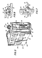
- FIGURE 2 is a perspective view of one of the plural modular ammunition packs utilized in the system of FIGURE 1;
- FIGURE 3 is a plan view in cross section of the ammunition packs of FIGURE 2;
- FIGURE 4 is a perspective view of a mechanized support frame for the ammunition packs of FIGURES 2 and 3;
- FIGURE 5 is a plan view of the support frame loaded with ammunition packs and illustrates the serpentine feed path negotiated by ammunition rounds during feeding operation;
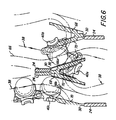
- FIGURE 6 is a fragmentary sectional view illustrating the transfer of ammunition rounds between magazine pack conveyors along their serpentine feed path;
- FIGURE 7 is a fragmentary plan view of structure for ensuring coordinated loading of ammunition packs; and
- FIGURE 8 is a sectional view taken along line 8-8 of FIGURE 7.
- Corresponding reference numerals refer to like parts throughout the several views of the drawings.
- The modular ammunition packaging and feed system of the present invention, generally indicated at 10 in FIGURE 1, is illustrated in its application to an armament system including a rapid-fire gun, generally indicated at 12. Live ammunition rounds are delivered by the feed system to the gun via a
transfer unit 13 andflexible chuting 14 and, if desired, empty shell casings or spent rounds are delivered back to the feed system viaflexible chuting 16 and atransfer unit 17 for storage. As seen generally in FIGURE 1, the feed system includes, in accordance with a signal feature of an embodiment of the invention, a magazine in the form of a plurality of modular magazine packs, generally indicated at 18, each including a multiplicity ofammunition rounds 20; the magazine packs being readily plugged into or installed in a mechanized frame, generally indicated at 22. - Referring to FIGURES 2 and 3, each
magazine pack 18 includes arectangular case 24 equipped with acarrying handle 26 for convenient portability. Avertical shaft 28 is journalled by the top and bottom walls of the case adjacent anopen front end 30 of the case, while a secondvertical shaft 32 is journalled adjacent the opposite, closedend 34 of the case. Upper andlower sprockets 36, affixed to each vertical shaft, drivingly engage a linear linkless ammunition loop conveyor, generally indicated at 38, consisting of a series of pivotally interconnectedammunition round carriers 40.Guide surfaces 42 withincase 24 maintainammunition rounds 20 in these carriers during conveyance along a loop path through the case interior.Openings 25 in the case sidewalls serve to reduce weight and to enable observance of the presence of rounds in the case. The upper end offront shaft 28 extends through the top case wall to accept a drive element in the form of aworm gear 44. Driven rotation of this worm gear turnssprockets 36 affixed toshaft 28 and thus propelsconveyor 38 to circulate theammunition rounds 20 in the loop path through the case interior. -
Frame 22, as seen in FIGURE 4, includes arectangular deck 46 supporting a pair ofupright mounting columns vertical posts 50 distributed along the longitudinal medial section of the deck between the columns. These posts are affixed at their upper ends totop plate 52 supported on the upper ends of the columns. Anelongated worm 54 included in a drive mechanism is journalled adjacent its ends incolumns top plate 52. Amotor 56 is drivingly connected to one end of the worm. To each side of the centrally mounted, longitudinally extending worm, the upper surface ofdeck 46 is configured with a pattern of transversely extending pairs ofgrooves 58 for slidingly acceptingfeet 60 depending from the bottom case wall of amagazine pack 18, as seen in FIGURE 2. Each pair of grooves defines a trackway for guiding a magazine pack as it is slid transversely into a load position, indicated at 60, with itsworm gear 44 in meshing engagement withworm 54.Deck 46 is also provided with pairs of longitudinally extendinggrooves 62 intersecting thetransverse grooves 58 to accommodate end loading of the magazine packs should side loading be obstructed. Gates mounted todeck 46 along its longitudinal outer edges (one seen at 63), are swung to upstanding, latched positions spanning the rear ends of the magazine packs to retain them in their respective load positions. - FIGURE 5 illustrates in plan view of opposed groups of
magazine packs 18 installed in their load positions with theirworm gears 44 in meshing engagement withworm 54 atpower takeoff sites 64 distributed along its length. Withmotor 56 energized to driveworm 54, power is applied to uniformly propel the ammunition conveyors 38 (FIGURE 3) in all of the magazine packs.Ammunition rounds 20 are successively transferred between conveyors of magazine packs in load positions on opposite sides of the worm in longitudinally staggered relation. There is thus achieved an overall movement ofammunition rounds 20 throughfeed system 10 along a serpentine path, as indicated 66, to convey successive rounds tohandoff sprockets 67 of exit transfer unit 13 (FIGURES 1 and 4) also driven bymotor 56. If spent shell cases are to be saved, they arrive from the gun viaflexible chuting 16 andtransfer unit 17 and are handed back to the nearest magazine pack bysprockets 69 for insertion into the serpentine feed path to progressively fill the packs situated there along. - These round transfers or handoffs between magazine pack conveyors are directed by pairs of V-shaped
guides 68 which are mounted by eachpost 58 in alignment with eachload position 60 as seen in FIGURE 4. Thus, when magazine packs are installed inload positions 60, the divergent ends of these V-shaped guides protrude into the openfront end 30 of theircases 24, as seen in FIGURE 6. In this connection, it is important to note from FIGURES 2 and 3 that, to accommodate protrusion of these guides and to permit successful operation, theconveyor carrier 40 located at the open end of each magazine pack is not loaded with an ammunition round 2u. Thus, when themagazine pack conveyors 38 are driven in unison, there is always an empty carrier swinging through the open end of each magazine pack to accept the handoff of an ammunition round from an adjacently opposed magazine pack. As can be seen in FIGURE 6, opposedcontrol surfaces 70 of longitudinallyadjacent guides 68 serve to route anammunition round 20 being conveyed in carrier 40a in the counter clockwise direction into the case open end along a transfer path 66a. Consequently, the ammunition round is picked from carrier 40a and handed off toconveyor carrier 40b of the adjacently opposed magazine pack, which was emptied and swung clockwise through the open front end of its magazine pack. The emptied carrier 40a swings around to accept transfer of an ammunition round from carrier 40C of the other adjacently opposed magazine pack as directed byopposed control surfaces 70guides 68 along atransfer path 66b. - It will be noted that round transfers from magazine pack to magazine pack are effected directly, i.e., without an intermediate handoff member. Thus, all of the
carriers 40 involved in theserpentine feed path 66 are filled, and there are consequently no gaps in the flow of ammunition to the gun. - When a combat vehicle, such as an attack helicopter, returns from a mission for rearming, the empty magazine packs are simply removed from their load positions and replaced with fully loaded ammunition packs. To provide requisite coordination of the loaded ammunition pack conveyor positions and proper operation of
feed system 10, all ammunition packs must be loaded with their one empty conveyor carriers in the same relative positions, i.e. front center positions in the open end of their pack cases. To this end, each magazine pack is provided with synchronizing provisions, which in the illustrated embodiment, take the form of aspring 70 mounted bycase 24 and having a slotted free end for engaging apin 72 upstanding from the upper face ofworm gear 44. The position ofpin 72 is coordinated with the front center position of acarrier 40 at theopen end 30 of themagazine case 24. Thus, if all of the carriers are loaded with an ammunition round except one, andconveyors 38 are all positioned with their one empty carrier at the front center position latched by engagement ofspring 70 withpin 72, then all the conveyors are in corresponding, coordinated positions. If a quarter turn ofworm gear 44 positions successive carriers at this front center position, then fourupstanding pins 72 may be provided at positions 90° apart. - As seen in FIGURE 7 and 8, this arrangement affords convenient means for guiding the magazine packs into their final load positions with
worm gears 44 smoothly slipping into meshing engagement withworm 54. To this end, at each load position 60 (FIGURE 4) the underside of frametop plate 52 carries a pair of longitudinally spaced guides 74 defining therebetween anarrow entryway 76 through which the foremostworm gear pin 72, diametrically opposed to the pin latched byspring 70, passes as a magazine pack is slid into its ultimate load position. This foremost pin clearsentryway 76 asworm gear 44 slips into meshing engagement withworm 54 at one of the power takeoff sites (FIGURE 5) and as the free end ofspring 70 is deflected upward by alatch release pin 78 depending fromplate 52. The spring is then disengaged frompin 72 and guides 74 assumes positions inside the circle swung by the pins during worm gear rotation. The worm gear is thus free to rotate when driven by the worm. - It remains to ensure that
worm 54 is in an appropriate reference angular position during loading such that the magazine pack worm gears can freely slip into coordinated meshing engagement therewith. This is achieved in the illustrated embodiment by providing adisk 80 keyed to the end of the worm extending beyondcolumn 49, as seen in FIGURE 4. The worm is indexed bymotor 56 until reference holes in the disk and column, commonly indicated at 82, are in alignment to accept apin 84 for retaining the worm in a coordinated angular loading position. - From the foregoing description, it is seen that the modular ammunition and feed system of the described embodiment accommodates a reload procedure which is both simple and fast. Empty or spent round filled magazine packs are simply removed and replaced with magazine packs filled with live rounds. It has been determined that one person can completely reload a complement of twenty four magazine packs in less than ten minutes. Logistical support is reduced to simply making preloaded magazine packs available at the rearming site. The loading of magazine packs does not consume power, since their conveyors are not cycled. This being the case, jams can not happen.
- It will also be appreciated that the described embodiment dramatically improves reliability. Over 90% of the moving, wearing parts in the system are in the magazine packs which are constantly being replaced. This, in effect, provides an automatic and continuous maintenance program. In the same manner, maintenance in the field is simplified. A feed malfunction would almost invariably involve a breakdown in one of the magazine packs, which is readily remedied by replacing it with another pack. Also to be noted is that a significant portion of the weight of the system of the present invention is represented by the magazine packs. Thus, with all or some of the magazine packs removed, the system weight is reduced. This is an important feature in airborne applications, enabling the aircraft to safely carry reconfigured armament arrays, such as additional rockets and/or missiles, and/or auxiliary fuel tanks for extended range.
- There has thus been provided a linear linkless ammunition feed system which utilizes a modular ammunition packaging approach and with which reloading is a simplified, inherently more reliable procedure involving minimal time and fewer, relatively unskilled personnel. Moreover the reloading procedure requires less logistical support in the field. The system can be emptied, to thus exhibit a significantly reduced weight, and is readily maintainable, convenient to troubleshoot and repair, and reliable in operation.
- It will be appreciated that certain changes may be made without departing from the scope of the invention, and that moreover the system may be adapted for the conveyance of articles other than ammunition.
Claims (20)
1) a plurality of side-by-side load positions, and
2) a drive mechanism including a separate power takeoff site aligned with each said load position;
1) a case,
2) an endless loop conveyor mounted within said case and having a plurality of carriers distributed along the conveyor length for individually accommodating an article for conveyance, and
3) a drive element drivingly connected with said conveyor and drivingly connectable with one of said power takeoff sites;
1) a plurality of side-by-side load positions, and
2) a drive mechanism including a separate power takeoff site aligned with each said load position;
1) a case,
2) an endless loop conveyor mounted within said case and having a plurality of carriers distributed along the conveyor length for individually accommodating a round of ammunition for conveyance, and
3) a drive element drivingly connected with said loop conveyor and driving connectable with said drive mechanism at said power takeoff site aligned with one of said load positions in which said magazine pack is disposed; and
Applications Claiming Priority (2)
| Application Number | Priority Date | Filing Date | Title |
|---|---|---|---|
| US07/422,711 US4982650A (en) | 1989-10-16 | 1989-10-16 | Modular ammunition packaging and feed system |
| US422711 | 1995-04-14 |
Publications (3)
| Publication Number | Publication Date |
|---|---|
| EP0424057A2 true EP0424057A2 (en) | 1991-04-24 |
| EP0424057A3 EP0424057A3 (en) | 1991-07-24 |
| EP0424057B1 EP0424057B1 (en) | 1995-03-08 |
Family
ID=23676039
Family Applications (1)
| Application Number | Title | Priority Date | Filing Date |
|---|---|---|---|
| EP90311243A Expired - Lifetime EP0424057B1 (en) | 1989-10-16 | 1990-10-15 | Modular ammunition packaging and feed system |
Country Status (8)
| Country | Link |
|---|---|
| US (1) | US4982650A (en) |
| EP (1) | EP0424057B1 (en) |
| JP (1) | JPH03140799A (en) |
| KR (1) | KR910008367A (en) |
| CA (1) | CA2021609A1 (en) |
| DE (1) | DE69017578T2 (en) |
| ES (1) | ES2069021T3 (en) |
| IL (1) | IL95797A0 (en) |
Cited By (4)
| Publication number | Priority date | Publication date | Assignee | Title |
|---|---|---|---|---|
| EP1319916A3 (en) * | 2001-12-07 | 2005-04-27 | Rheinmetall Landsysteme GmbH | Subdivided magazine with a releasable additional magazine |
| US9200881B1 (en) | 2011-10-24 | 2015-12-01 | F. Richard Langner | Systems and methods for an improved firing assembly |
| US9322625B1 (en) | 2011-10-24 | 2016-04-26 | F. Richard Langner | Systems and methods for launching water from a disrupter cannon |
| US9453713B1 (en) | 2011-10-24 | 2016-09-27 | F. Richard Langner | Systems and methods for ammunition for a disrupter cannon |
Families Citing this family (13)
| Publication number | Priority date | Publication date | Assignee | Title |
|---|---|---|---|---|
| US5149909A (en) * | 1991-06-13 | 1992-09-22 | North American Dynamics | Opposed round parallel path single bay ammunition feed system |
| US5218162A (en) * | 1992-01-21 | 1993-06-08 | General Electric Co. | Double-ended ammunition handling system for rapid-fire guns |
| US5440964A (en) * | 1994-08-03 | 1995-08-15 | Martin Marietta Corporation | Ammunition magazine drive system |
| FR2825144B1 (en) * | 2001-05-28 | 2003-09-05 | Giat Ind Sa | STORAGE STORE FOR PROPULSIVE CHARGING MODULES |
| US6718862B1 (en) * | 2002-10-01 | 2004-04-13 | Paul H. Sanderson | Sponson tow plate-mounted helicopter armament apparatus and associated methods |
| DE202009007415U1 (en) | 2009-05-25 | 2010-08-26 | Rheinmetall Waffe Munition Gmbh | Modular weapon carrier |
| IL200036A (en) * | 2009-07-23 | 2015-02-26 | Rafael Advanced Defense Sys | System and method for protected reloading of a remote controlled weapon station |
| US20120167750A1 (en) * | 2011-01-04 | 2012-07-05 | Lockheed Martin Corporation | Rapid fire launch system |
| US9097476B2 (en) | 2012-05-25 | 2015-08-04 | Hasbro, Inc. | Projectile launcher with rotatable clip connector |
| US8434397B1 (en) | 2012-06-08 | 2013-05-07 | The United States Of America As Represented By The Secretary Of The Navy | Helicopter weapon mounting system |
| SA115360300B1 (en) | 2014-02-14 | 2017-08-29 | ميريل افياشين، انك. | Modular weapon station system |
| SE541259C2 (en) * | 2016-06-21 | 2019-05-21 | Bae Systems Bofors Ab | System and method for loading ammunition to a primary magazine in an automatic gun |
| US10488148B2 (en) * | 2017-10-13 | 2019-11-26 | Alex Brands Buzz Bee Toys(HK)Limited | Toy gun with moveable magazines |
Citations (3)
| Publication number | Priority date | Publication date | Assignee | Title |
|---|---|---|---|---|
| US2951422A (en) * | 1956-05-11 | 1960-09-06 | Armament Components Inc | Article handling system for cartridge feeding |
| US3045553A (en) * | 1959-02-13 | 1962-07-24 | Mach Tool Works Oerlikon Admin | Magazine container for automatic fire arms |
| DE3200726A1 (en) * | 1981-05-15 | 1982-12-02 | Western Design Corp., Irvine, Calif. | AMMUNITION MAGAZINE |
Family Cites Families (10)
| Publication number | Priority date | Publication date | Assignee | Title |
|---|---|---|---|---|
| US1314013A (en) * | 1919-08-26 | Cartridge-feeding device | ||
| US2321142A (en) * | 1940-08-01 | 1943-06-08 | Brewster Aeronautical Corp | Magazine for automatic guns |
| NL94288C (en) * | 1955-08-16 | |||
| DE1072517B (en) * | 1957-06-14 | |||
| CH455577A (en) * | 1964-05-13 | 1968-07-15 | Bofors Ab | Device for conveying cartridges in the cartridge magazine of a gun |
| GB1138286A (en) * | 1965-03-10 | 1968-12-27 | Bofors Ab | Round feeding mechanism for an automatic gun |
| US3369454A (en) * | 1965-05-06 | 1968-02-20 | Bofors Ab | Device for feeding cartridges deposited in a twin cartridge magazine of a gun |
| US3314182A (en) * | 1965-10-11 | 1967-04-18 | Earle M Harvey | Dual magazine system for firearms |
| FR2130734A5 (en) * | 1969-10-10 | 1972-11-10 | Inst Francais Du Petrole | |
| US4468875A (en) * | 1982-05-20 | 1984-09-04 | Creative Metal Forming, Inc. | Cartridge magazine for direct ejection of a cartridge into the firing chamber of a firearm |
-
1989
- 1989-10-16 US US07/422,711 patent/US4982650A/en not_active Expired - Fee Related
-
1990
- 1990-07-19 CA CA002021609A patent/CA2021609A1/en not_active Abandoned
- 1990-09-26 IL IL95797A patent/IL95797A0/en not_active IP Right Cessation
- 1990-10-09 JP JP2272038A patent/JPH03140799A/en active Pending
- 1990-10-15 ES ES90311243T patent/ES2069021T3/en not_active Expired - Lifetime
- 1990-10-15 EP EP90311243A patent/EP0424057B1/en not_active Expired - Lifetime
- 1990-10-15 KR KR1019900016343A patent/KR910008367A/en active IP Right Grant
- 1990-10-15 DE DE69017578T patent/DE69017578T2/en not_active Expired - Fee Related
Patent Citations (3)
| Publication number | Priority date | Publication date | Assignee | Title |
|---|---|---|---|---|
| US2951422A (en) * | 1956-05-11 | 1960-09-06 | Armament Components Inc | Article handling system for cartridge feeding |
| US3045553A (en) * | 1959-02-13 | 1962-07-24 | Mach Tool Works Oerlikon Admin | Magazine container for automatic fire arms |
| DE3200726A1 (en) * | 1981-05-15 | 1982-12-02 | Western Design Corp., Irvine, Calif. | AMMUNITION MAGAZINE |
Cited By (4)
| Publication number | Priority date | Publication date | Assignee | Title |
|---|---|---|---|---|
| EP1319916A3 (en) * | 2001-12-07 | 2005-04-27 | Rheinmetall Landsysteme GmbH | Subdivided magazine with a releasable additional magazine |
| US9200881B1 (en) | 2011-10-24 | 2015-12-01 | F. Richard Langner | Systems and methods for an improved firing assembly |
| US9322625B1 (en) | 2011-10-24 | 2016-04-26 | F. Richard Langner | Systems and methods for launching water from a disrupter cannon |
| US9453713B1 (en) | 2011-10-24 | 2016-09-27 | F. Richard Langner | Systems and methods for ammunition for a disrupter cannon |
Also Published As
| Publication number | Publication date |
|---|---|
| US4982650A (en) | 1991-01-08 |
| DE69017578T2 (en) | 1995-09-28 |
| CA2021609A1 (en) | 1991-04-17 |
| EP0424057B1 (en) | 1995-03-08 |
| DE69017578D1 (en) | 1995-04-13 |
| ES2069021T3 (en) | 1995-05-01 |
| KR910008367A (en) | 1991-05-31 |
| EP0424057A3 (en) | 1991-07-24 |
| JPH03140799A (en) | 1991-06-14 |
| IL95797A0 (en) | 1991-06-30 |
Similar Documents
| Publication | Publication Date | Title |
|---|---|---|
| EP0424057B1 (en) | Modular ammunition packaging and feed system | |
| US3696704A (en) | Ammunition bulk loader | |
| US5782157A (en) | Chuting assembly for ammunition magazine feed | |
| US4424735A (en) | Linear linkless ammunition magazine | |
| CA1316734C (en) | Magazine ammunition conveying system | |
| US4137820A (en) | Ammunition handling and loading system | |
| US4819518A (en) | Loading system for containers holding cartridged ammunition | |
| US3045553A (en) | Magazine container for automatic fire arms | |
| EP0391978A1 (en) | A missile launcher. | |
| JPH0285699A (en) | Article treater | |
| US6205904B1 (en) | Mechanism for feeding munition elements to an artillery cannon | |
| CA1239043A (en) | Assembly for feeding ammunition in armored vehicle | |
| US4976185A (en) | Ammunition feed | |
| US3170372A (en) | Loader and magazine mechanism | |
| EP0493918B1 (en) | Magazine and conveyor | |
| US6345562B1 (en) | Method and device for feeding ammunition to automatic cannon | |
| US5149909A (en) | Opposed round parallel path single bay ammunition feed system | |
| EP0727636A2 (en) | Conveyor | |
| US5170006A (en) | Propellant magazine for field artillery piece | |
| US5115713A (en) | Apparatus for the infeed of cartridges to a firing weapon | |
| JPH04281197A (en) | Ammunition operating device for supplying ammunition from magazine to quick-fire gun | |
| US6742436B2 (en) | Automatic loading process and system for a weapon mounted on a ship | |
| US5932831A (en) | Device for feeding ammunition into an airbornee weapon and aircraft equipped with such a device | |
| US3766823A (en) | Ammunition handling system | |
| EP0029644B1 (en) | Variable capacity crossfeeding conveyer, in particular for automatic gun feed mechanisms |
Legal Events
| Date | Code | Title | Description |
|---|---|---|---|
| PUAI | Public reference made under article 153(3) epc to a published international application that has entered the european phase |
Free format text: ORIGINAL CODE: 0009012 |
|
| AK | Designated contracting states |
Kind code of ref document: A2 Designated state(s): CH DE ES FR GB IT LI |
|
| PUAL | Search report despatched |
Free format text: ORIGINAL CODE: 0009013 |
|
| AK | Designated contracting states |
Kind code of ref document: A3 Designated state(s): CH DE ES FR GB IT LI |
|
| 17P | Request for examination filed |
Effective date: 19911216 |
|
| 17Q | First examination report despatched |
Effective date: 19930729 |
|
| GRAA | (expected) grant |
Free format text: ORIGINAL CODE: 0009210 |
|
| AK | Designated contracting states |
Kind code of ref document: B1 Designated state(s): CH DE ES FR GB IT LI |
|
| REF | Corresponds to: |
Ref document number: 69017578 Country of ref document: DE Date of ref document: 19950413 |
|
| ET | Fr: translation filed | ||
| REG | Reference to a national code |
Ref country code: ES Ref legal event code: FG2A Ref document number: 2069021 Country of ref document: ES Kind code of ref document: T3 |
|
| ITF | It: translation for a ep patent filed |
Owner name: SAIC BREVETTI S.R.L. |
|
| PGFP | Annual fee paid to national office [announced via postgrant information from national office to epo] |
Ref country code: FR Payment date: 19950913 Year of fee payment: 6 Ref country code: CH Payment date: 19950913 Year of fee payment: 6 |
|
| PGFP | Annual fee paid to national office [announced via postgrant information from national office to epo] |
Ref country code: DE Payment date: 19950925 Year of fee payment: 6 |
|
| PGFP | Annual fee paid to national office [announced via postgrant information from national office to epo] |
Ref country code: GB Payment date: 19950927 Year of fee payment: 6 |
|
| PGFP | Annual fee paid to national office [announced via postgrant information from national office to epo] |
Ref country code: ES Payment date: 19951009 Year of fee payment: 6 |
|
| PLBE | No opposition filed within time limit |
Free format text: ORIGINAL CODE: 0009261 |
|
| STAA | Information on the status of an ep patent application or granted ep patent |
Free format text: STATUS: NO OPPOSITION FILED WITHIN TIME LIMIT |
|
| 26N | No opposition filed | ||
| PG25 | Lapsed in a contracting state [announced via postgrant information from national office to epo] |
Ref country code: GB Effective date: 19961015 |
|
| PG25 | Lapsed in a contracting state [announced via postgrant information from national office to epo] |
Ref country code: ES Free format text: LAPSE BECAUSE OF THE APPLICANT RENOUNCES Effective date: 19961016 |
|
| PG25 | Lapsed in a contracting state [announced via postgrant information from national office to epo] |
Ref country code: LI Effective date: 19961031 Ref country code: CH Effective date: 19961031 |
|
| GBPC | Gb: european patent ceased through non-payment of renewal fee |
Effective date: 19961015 |
|
| REG | Reference to a national code |
Ref country code: CH Ref legal event code: PL |
|
| PG25 | Lapsed in a contracting state [announced via postgrant information from national office to epo] |
Ref country code: FR Effective date: 19970630 |
|
| PG25 | Lapsed in a contracting state [announced via postgrant information from national office to epo] |
Ref country code: DE Effective date: 19970701 |
|
| REG | Reference to a national code |
Ref country code: FR Ref legal event code: ST |
|
| REG | Reference to a national code |
Ref country code: ES Ref legal event code: FD2A Effective date: 19991007 |
|
| PG25 | Lapsed in a contracting state [announced via postgrant information from national office to epo] |
Ref country code: IT Free format text: LAPSE BECAUSE OF NON-PAYMENT OF DUE FEES;WARNING: LAPSES OF ITALIAN PATENTS WITH EFFECTIVE DATE BEFORE 2007 MAY HAVE OCCURRED AT ANY TIME BEFORE 2007. THE CORRECT EFFECTIVE DATE MAY BE DIFFERENT FROM THE ONE RECORDED. Effective date: 20051015 |