EP0418527A2 - Method to prepare a roll of breadths of print cloth for an automatic reel changer - Google Patents
Method to prepare a roll of breadths of print cloth for an automatic reel changer Download PDFInfo
- Publication number
- EP0418527A2 EP0418527A2 EP90115006A EP90115006A EP0418527A2 EP 0418527 A2 EP0418527 A2 EP 0418527A2 EP 90115006 A EP90115006 A EP 90115006A EP 90115006 A EP90115006 A EP 90115006A EP 0418527 A2 EP0418527 A2 EP 0418527A2
- Authority
- EP
- European Patent Office
- Prior art keywords
- roll
- adhesive
- reel
- beginning
- web
- Prior art date
- Legal status (The legal status is an assumption and is not a legal conclusion. Google has not performed a legal analysis and makes no representation as to the accuracy of the status listed.)
- Withdrawn
Links
Images
Classifications
-
- B—PERFORMING OPERATIONS; TRANSPORTING
- B65—CONVEYING; PACKING; STORING; HANDLING THIN OR FILAMENTARY MATERIAL
- B65H—HANDLING THIN OR FILAMENTARY MATERIAL, e.g. SHEETS, WEBS, CABLES
- B65H19/00—Changing the web roll
- B65H19/10—Changing the web roll in unwinding mechanisms or in connection with unwinding operations
- B65H19/102—Preparing the leading end of the replacement web before splicing operation; Adhesive arrangements on leading end of replacement web; Tabs and adhesive tapes for splicing
-
- B—PERFORMING OPERATIONS; TRANSPORTING
- B65—CONVEYING; PACKING; STORING; HANDLING THIN OR FILAMENTARY MATERIAL
- B65H—HANDLING THIN OR FILAMENTARY MATERIAL, e.g. SHEETS, WEBS, CABLES
- B65H2301/00—Handling processes for sheets or webs
- B65H2301/40—Type of handling process
- B65H2301/46—Splicing
- B65H2301/4606—Preparing leading edge for splicing
- B65H2301/4607—Preparing leading edge for splicing by adhesive tape
Definitions
- the present invention relates to a method for preparing a roll of web-shaped printing material for use in a rotary printing press with an automatic roll changer.
- the printing material for example paper
- the printing material web is unwound from a roll, which is clamped in a device, hereinafter referred to briefly as a roll changer, which is arranged at the paper inlet of the printing press.
- a roll changer which is arranged at the paper inlet of the printing press.
- the roll changer has at least two tensioning devices for receiving at least one first printing material web roll to be unwound and a second printing material web roll to be unwound after the first roll, a device for driving at least one of the printing material web rolls and a device for automatically gluing the beginning of the second roll to the end the first on.
- the beginning of the second roll can only be reliably adhered to the end of the first roll if the respective second roll is prepared in a suitable manner.
- the above-described method for preparing a new roll of printing material web is disadvantageous in that the edge of the web is only glued to the outer printing material web layer in some places.
- the unwinding speed of the old roll can press air under the beginning of the new roll due to the direction of rotation and thus lead to a lifting of the beginning of the roll from the underlying web.
- Another disadvantage is that the perforation of the adhesive strips must be precisely controlled with regard to the position and depth of the perforation, on the one hand to prevent perforation of the printing material web, but on the other hand to completely perforate the adhesive strips.
- the adhesive strips form corners with the edge of the printing material web, from which the printing material web can tear if all the adhesive strips are not separated evenly during the adhesive process. It is precisely in this regard also to be regarded as disadvantageous that the start edge of the roll is cut at right angles to the unwinding direction, because it is imperative that all perforations tear open at the same time. Otherwise, as in the cases mentioned before, there is an increase in waste.
- the object of the invention is therefore to provide a method with which a material web replacement roll is prepared for use in a roll changer, so that even at high unwinding speed it is ensured that the beginning of the roll of the new roll is glued securely and trouble-free to the remaining web.
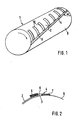
- a paper roll 1 as an example for a printing material web roll which has been prepared in the manner according to the invention for insertion into a roll changer of a rotary printing press.
- the paper roll 1 to be glued to the first unwound paper roll is unpacked and the damaged paper layers are removed.
- the edge 3 of the roll start 2 is cut off at an angle ⁇ between the unwinding direction and the roll start edge 3.
- the angle ⁇ must be less than 90 ° and should suitably be between 60 ° and 80 ° be.
- the edge 3 of the roll is glued to the outer paper layer 8 underneath with a specially designed adhesive strip 4 spanning the entire width of the roll 1.
- the adhesive strip 4 to be used according to the invention is divided into three zones 5, 6, 7 (FIG. 2). Of these zones, one outer zone 5 is self-adhesive on both sides, the middle zone 6 is non-adhesive and the other outer zone 7 is self-adhesive on one side.
- the central zone 6 is provided with a perforation 9 running in the longitudinal direction of the strip. The adhesive strip 4 is now applied in such a way that the central zone 6 comes to rest on the edge 3 of the roll start 2 and that one adhesive zone 5 sticks to the roll start 2 and the other adhesive zone 7 to the adjacent section 8 of the outer paper layer.
- the outer surface of the beginning of the roll 2 is provided with an adhesive in order to form an adhesive surface which ensures that the perforation is torn open.
- the outer surface is preferably provided from the adhesive strip 4 with strips 10 which are adhesive on both sides and run parallel to the unwinding direction, or with adhesive applied to the surface. The end section of the remaining roll to be replaced is then pressed onto this adhesive surface during roll gluing.
- the strips 10 can also be applied in any other direction which has proven to be advantageous than that which is parallel to the unwinding direction.
- the zone 5 of the adhesive strip 4 can be self-adhesive on one side, the adhesive then also having to be applied to the zone 5.
- the strips 10 are applied with a simultaneous use of an adhesive strip 4 with a zone 5 which is adhesive on one side, from a line running on the zone 5 directly next to the perforation.
- All steps of the roll preparation described above can either be carried out by hand, in some cases also using hand-held devices, such as an adhesive tape dispenser, or else fully automatically.
- hand-held devices such as an adhesive tape dispenser
- the reel changer or one or more upstream stations for the individual steps are suitably equipped with devices known per se, such as a machine-operated knife.
- the method according to the invention for the automated preparation of a paper roll 1 or a roll of other web material to be printed for use in a rotary printing press with an automatic roll changer essentially has the following advantages: -
- the parts used to glue the beginning of the roll 2 cannot come off the paper.
- - Thanks to the defined slope of the roll start 2, easy and precise tearing of the roll 1 is ensured when gluing the roll.
- - The effect of lifting the beginning of the roll from the underlying web layer, which leads to incorrect sticking, is avoided.
- the adhesive-free zone 6 of the adhesive strip 4 enables the adhesive preparation to be carried out quickly and with simple means, even with simple means that can be automated, since the edge of the paper roll 3 and the perforation 9 do not have to match exactly.
- the entire preparation of the roll and in particular the preparation of the adhesive surface are very easy to automate.
Abstract
Description
Die vorliegende Erfindung betrifft ein Verfahren zum Vorbereiten einer Rolle bahnförmigen Bedruckstoffs für eine Verwendung in einer Rotationsdruckmaschine mit automatischem Rollenwechsler.The present invention relates to a method for preparing a roll of web-shaped printing material for use in a rotary printing press with an automatic roll changer.
Bei Rotationsdruckmaschinen wird der Bedruckstoff, zum Beispiel Papier, dem Druckwerk in Form einer Bedruckstoffbahn zugeführt. Dabei wird die Bedruckstoffbahn von einer Rolle abgewickelt, die in einer im folgenden kurz als Rollenwechsler bezeichneten Vorrichtung, die am Papiereinlauf der Druckmaschine angeordnet ist, eingespannt ist. Um die insbesondere im Zeitungsdruck einzuhaltende Bedingung des unterbrechungsfreien Druckens erfüllen zu können, erfolgt das Ersetzen einer abgewickelten Bedruckstoffbahnrolle durch eine neue vorteilhafterweise im fliegenden Wechsel. Dazu weist der Rollenwechsler wenigstens zwei Spannvorrichtungen zur Aufnahme von wenigstens einer unmittelbar abzuwickelnden ersten Bedruckstoffbahnrolle und einer im Anschluß an die erste Rolle abzuwickelnden zweiten Bedruckstoffbahnrolle, eine Vorrichtung zum Antreiben wenigstens einer der Bedruckstoffbahnrollen und eine Vorrichtung zum automatischen Ankleben des Anfangs der zweiten Rolle an das Ende der ersten auf.In rotary printing machines, the printing material, for example paper, is fed to the printing unit in the form of a printing material web. In this case, the printing material web is unwound from a roll, which is clamped in a device, hereinafter referred to briefly as a roll changer, which is arranged at the paper inlet of the printing press. In order to be able to meet the requirement of uninterrupted printing, particularly in newspaper printing, a unwound printing web roll is replaced by a new one, advantageously on the fly. For this purpose, the roll changer has at least two tensioning devices for receiving at least one first printing material web roll to be unwound and a second printing material web roll to be unwound after the first roll, a device for driving at least one of the printing material web rolls and a device for automatically gluing the beginning of the second roll to the end the first on.
Ein zuverlässiges Ankleben des Anfangs der zweiten Rolle an das Ende der ersten Rolle ist jedoch nur möglich, wenn die jeweilige zweite Rolle in geeigneter Weise vorbereitet wird.However, the beginning of the second roll can only be reliably adhered to the end of the first roll if the respective second roll is prepared in a suitable manner.
Aus der EP 0 129 238 ist bekannt, die neue Rolle folgendermaßen vorzübereiten. Zunächst wird - nach erfolgtem Aus-packen der Rolle und Entfernen der beschädigten äußeren Lagen - die Kante der Bahn gerade geschnitten. Dann wird die Kante der Bahn auf der äußeren Lage mittels einer Mehrzahl von Klebestreifen festgeklebt. Die dabei verwendeten Klebestreifen weisen auf der Klebeseite eine in Streifenlängsrichtung verlaufende nichtklebende Mittelzone und rechts und links davon je eine Klebezane auf. Die Klebestreifen werden nach der Rollenkante ausgerichtet und so aufgebracht, daß die Mittelzone auf der Kante der Bahn zu liegen kommt und so die eine Klebezone auf dem Rollenende und die andere Klebezone auf dem daneben liegenden Abschnitt der äußeren Lage klebt.It is known from EP 0 129 238 to prepare the new role as follows. First, after unpacking the roll and removing the damaged outer layers, the edge of the web is cut straight. Then the edge of the web is glued to the outer layer by means of a plurality of adhesive strips. The adhesive strips used have an in on the adhesive side Non-adhesive central zone running in the longitudinal direction of the strip and an adhesive membrane on the right and left of it. The adhesive strips are aligned with the edge of the roll and applied so that the middle zone comes to rest on the edge of the web and so one adhesive zone sticks to the end of the roll and the other adhesive zone sticks to the adjacent section of the outer layer.
Wenn dann die Rolle in den Rollenwechsler eingespannt ist, wird in der Mittelzone des Klebestreifens durch eine entsprechend ausgelegte Vorrichtung eine Perforierung angebracht, um das Aufreißen der Klebestreifen beim Ankleben des Rollenanfangs an die alte Bahn zu erleichtern.When the roll is then clamped in the roll changer, a perforation is made in the central zone of the adhesive strip by means of an appropriately designed device in order to facilitate the tearing open of the adhesive strips when the roll start is glued to the old web.
Das vorstehend beschriebene Verfahren zum Vorbereiten einer neuen Bedruckstoffbahnrolle ist insofern nachteilig, als die Kante der Bahn nur an einigen Stellen auf der äußeren Bedruckstoffbahnlage festgeklebt wird. Dadurch kann sich beim Beschleunigen der neuen Rolle auf die Abwickelgeschwindigkeit der alten Rolle aufgrund der Drehrichtung Luft unter den Rollenanfang der neuen Rolle drücken und so zu einem Abheben des Rollenanfangs von der darunterliegenden Bahnlage führen. Das bedeutet die Gefahr eines unkontrollierbaren Verhaltens der neuen Rolle während des Anklebevorgangs, was u.a. bei exzentrisch laufenden Rollen zu ungewolltem, verfrühtem Ankleben führt, und insbesondere ein nicht über die gesamte Breite der Rolle gleichmäßiges Mitreißen der Bahn im Zeitpunkt der Klebung, was zu einer erhöhten Makulaturerzeugung oder Störung des Druckbetriebs führen kann.The above-described method for preparing a new roll of printing material web is disadvantageous in that the edge of the web is only glued to the outer printing material web layer in some places. As a result, when the new roll is accelerating, the unwinding speed of the old roll can press air under the beginning of the new roll due to the direction of rotation and thus lead to a lifting of the beginning of the roll from the underlying web. This means the risk of uncontrollable behavior of the new roll during the gluing process, which among other things. in the case of eccentrically running rolls leads to unwanted, premature gluing, and in particular the fact that the web is not carried along uniformly over the entire width of the roll at the time of gluing, which can lead to increased waste production or malfunction of the printing operation.
Nachteilig ist ferner, daß das Perforieren der Klebestreifen hinsichtlich der Lage und der Tiefe der Perforierung genau gesteuert werden muß, um einerseits ein Perforieren der Bedruckstoffbahn zu verhindern, um andererseits aber die Klebestreifen vollständig zu perforieren. Außerdem bilden die Klebestreifen mit der Kante der Bedruckstoffbahn Ecken, von denen ausgehend die Bedruckstoffbahn zerreißen kann, wenn beim Klebevorgang nicht alle Klebestreifen gleichmäßig aufgetrennt werden. Gerade in dieser Hinsicht ist es auch als nachteilig anzusehen, daß die Rollenanfangskante im rechten Winkel zur Abwickelrichtung geschnitten ist, denn so müssen alle Perforierungen unbedingt gleichzeitig aufreißen. Widrigenfalls kommt es, wie auch bei den davor genannten Fällen zu einem erhöhten Makulaturaufkommen.Another disadvantage is that the perforation of the adhesive strips must be precisely controlled with regard to the position and depth of the perforation, on the one hand to prevent perforation of the printing material web, but on the other hand to completely perforate the adhesive strips. In addition, the adhesive strips form corners with the edge of the printing material web, from which the printing material web can tear if all the adhesive strips are not separated evenly during the adhesive process. It is precisely in this regard also to be regarded as disadvantageous that the start edge of the roll is cut at right angles to the unwinding direction, because it is imperative that all perforations tear open at the same time. Otherwise, as in the cases mentioned before, there is an increase in waste.
Aufgabe der Erfindung ist es daher, ein Verfahren anzugeben, mit dem eine Materialbahnersatzrolle so für die Verwendung in einem Rollenwechsler vorbereitet wird, daß auch bei hoher Abwickelgeschwindigkeit gewährleistet ist, daß der Rollenanfang der neuen Rolle sicher und störungsfrei an die auslaufende Restbahn angeklebt wird.The object of the invention is therefore to provide a method with which a material web replacement roll is prepared for use in a roll changer, so that even at high unwinding speed it is ensured that the beginning of the roll of the new roll is glued securely and trouble-free to the remaining web.
Diese Aufgabe wird durch ein Verfahren nach Patentanspruch 1 gelöst.This object is achieved by a method according to
Vorteilhafte Weiterbildungen des erfindungsgemäßen Verfahrens sind Gegenstand von Unteransprüchen.Advantageous developments of the method according to the invention are the subject of dependent claims.
Weitere Merkmale und Zweckmäßigkeiten der Erfindung ergeben sich aus der Beschreibung eines Ausführungsbeispiels anhand der Figuren. Es zeigen:
- Fig. 1 eine schematische Darstellung einer Papierrolle, die nach dem erfindungsgemäßen Verfahren vorbereitet worden ist, und
- Fig. 2 eine schematische Schnittdarstellung des erfindungsgemäß zu verwendenden Klebestreifens
- Fig. 1 is a schematic representation of a paper roll that has been prepared by the method according to the invention, and
- Fig. 2 is a schematic sectional view of the adhesive strip to be used according to the invention
In Fig. 1 ist eine Papierrolle 1 als ein Beispiel für eine Bedruckstoffbahnrolle dargestellt, die in erfindungsgemäßer Weise zum Einsetzen in einen Rollenwechsler einer Rotationsdruckmaschine vorbereitet worden ist. Die an die erste, abgewickelte Papierrolle anzuklebende Papierrolle 1 wird ausgepackt, und es werden die beschädigten Papierlagen abgetragen. Dann wird die Kante 3 des Rollenanfangs 2 unter einem Winkel α zwischen der Abwickelrichtung und der Rollenanfangskante 3 schräg abgeschnitten. Der Winkel α muß kleiner als 90° sein und sollte zweckmäßig zwischen 60° und 80° betragen. Anschließend wird die Rollenanfangskante 3 mit einem die gesamte Breite der Rolle 1 überspannenden, speziell ausgebildeten Klebestreifen 4 auf der darunterliegenden äußeren Papierlage 8 festgeklebt.1 shows a
Der erfindungsgemäß zu verwendende Klebestreifen 4 ist in drei Zonen 5, 6, 7 unterteilt (Fig. 2). Von diesen Zonen ist die eine äußere Zone 5 beidseitig selbstklebend, die mittlere Zone 6 nichtklebend und die andere äußere Zone 7 einseitig selbstklebend ausgebildet. Die mittlere Zone 6 ist mit einer in Streifenlängsrichtung verlaufenden Perforierung 9 versehen. Der Klebestreifen 4 wird nun derart aufgebracht, daß die mittlere Zone 6 auf der Kante 3 des Rollenanfangs 2 zu liegen kommt und daß die eine Klebezone 5 auf dem Rollenanfang 2 und die andere Klebezone 7 auf dem angrenzenden Abschnitt 8 der äußeren Papierlage klebt.The adhesive strip 4 to be used according to the invention is divided into three
Durch das Abschneiden der Kante 3 unter einem anderen Winkel als dem rechten Winkel und das damit einhergehende schräge Anbringen des Klebestreifens 4 wird erreicht, daß die Perforierung 9 des Klebestreifens 4 beim Rollenkleben während des Rollenwechsels von einer Seite her zuverlässig aufgerissen wird.By cutting off the
Abschließend wird die Außenoberfläche des Rollenanfangs 2 mit einem Klebemittel versehen, um eine Anklebefläche zu bilden, die ein sicheres Aufreißen der Perforierung gewährleistet. Und zwar wird die Außenoberfläche vorzugsweise vom Klebestreifen 4 aus mit zur Abwickelrichtung parallel verlaufenden beidseitig klebenden Streifen 10 oder mit flächig aufgetragenem Klebstoff versehen. Auf diese Anklebefläche wird dann beim Rollenkleben der Endabschnitt der zu ersetzenden Restrolle gedrückt.Finally, the outer surface of the beginning of the
Wenn es beim speziellen Ausführungsbeispiel günstiger ist, können die Streifen 10 auch in jeder anderen, sich als vorteilhaft erweisenden Richtung als der zur Abwickelrichtung parallelen aufgetragen werden. Im Falle des flächigen Auftragens von Klebstoff kann die Zone 5 des Klebestreifens 4 einseitig selbstklebend ausgebildet sein, wobei dann der Klebstoff auch auf die Zone 5 aufzutragen ist.If it is more favorable in the specific embodiment, the
In einer weiteren vorteilhaften Ausführungsform der Erfindung werden die Streifen 10 bei gleichzeitiger Verwendung eines Klebestreifens 4 mit einseitig klebender Zone 5 von einer auf der Zone 5 unmittelbar neben der Perforierung verlaufenden Linie aus aufgebracht.In a further advantageous embodiment of the invention, the
Alle Schritte der vorstehend beschriebenen Rollenvorbereitung können entweder von Hand, dabei teilweise auch unter Verwendung von Handgeräten, wie etwa eines Klebestreifenspenders, oder aber auch vollautomatisch ausgeführt werden. Im letzteren Fall ist der Rollenwechsler oder ein oder mehrere vorgeschaltete Stationen für die einzelnen Schritte in geeigneter Weise mit an sich bekannten Vorrichtungen, wie etwa einem maschinell betätigbaren Messer, ausgestattet.All steps of the roll preparation described above can either be carried out by hand, in some cases also using hand-held devices, such as an adhesive tape dispenser, or else fully automatically. In the latter case, the reel changer or one or more upstream stations for the individual steps are suitably equipped with devices known per se, such as a machine-operated knife.
Das erfindungsgemäße Verfahren zum automatisierbaren Vorbereiten einer Papierrolle 1 oder einer Rolle sonstigen zu bedruckenden Bahnmaterials für eine Verwendung in einer Rotationsdruckmaschine mit automatischem Rollenwechsler weist im wesentlichen folgende Vorteile auf:
- Die zum Kleben des Rollenanfangs 2 verwendeten Teile können sich nicht vom Papier lösen.
- Dank der definierten Schräge des Rollenanfangs 2 ist ein leichtes und präzises Aufreißen der Rolle 1 beim Rollenkleben gesichert.
- Der zu Fehlklebungen führende Effekt des Abhebens des Rollenanfangs von der darunterliegenden Bahnlage wird vermieden.
- Die kleberfreie Zone 6 des Klebestreifens 4 ermöglicht, die Klebevorbereitung schnell und mit einfachen Mitteln, auch mit automatisierbaren einfachen Mitteln, auszuführen, da die Papierrollenanfangskante 3 und die Perforierung 9 nicht genau übereinstimmen müssen.
- Die gesamte Vorbereitung der Rolle und insbesondere die Vorbereitung der Anklebefläche sind denkbar einfach zu automatisieren.The method according to the invention for the automated preparation of a
- The parts used to glue the beginning of the
- Thanks to the defined slope of the
- The effect of lifting the beginning of the roll from the underlying web layer, which leads to incorrect sticking, is avoided.
- The adhesive-free zone 6 of the adhesive strip 4 enables the adhesive preparation to be carried out quickly and with simple means, even with simple means that can be automated, since the edge of the
- The entire preparation of the roll and in particular the preparation of the adhesive surface are very easy to automate.
Claims (8)
- am Rollenanfang eine Rollenanfangskante mit einem gegenüber der Abwickelrichtung von 90° verschiedenen Winkel geschnitten wird,
- ein Klebestreifen, der über die gesamte Länge in drei Zonen unterteilt ist, von denen die mittlere Zone nicht klebend ausgebildet und in Längsrichtung perforiert ist, über die gesamte Breite der Bedruckstoffrolle derart aufgebracht wird, daß der Rollenanfang auf der äußeren Bedruckstoffbahnlage festgeklebt wird und daß die Rollenanfangskante innerhalb der mittleren Zone des Klebestreifens liegt, und
- auf der äußeren Oberfläche des Rollenanfangs zum Bilden einer Anklebefläche ein Klebemittel aufgebracht wird.1. A method for preparing a printing material web roll to be used in a roll changer of a rotary printing press, in which
- at the start of the roll, a start edge of the roll is cut at an angle different from the unwinding direction,
- An adhesive strip, which is divided over the entire length into three zones, of which the central zone is non-adhesive and perforated in the longitudinal direction, is applied over the entire width of the printing material roll in such a way that the beginning of the roll is glued to the outer printing material layer and that the leading edge of the roll lies within the central zone of the adhesive strip, and
- An adhesive is applied to the outer surface of the beginning of the roll to form an adhesive surface.
Applications Claiming Priority (2)
| Application Number | Priority Date | Filing Date | Title |
|---|---|---|---|
| DE3931159 | 1989-09-19 | ||
| DE3931159 | 1989-09-19 |
Publications (2)
| Publication Number | Publication Date |
|---|---|
| EP0418527A2 true EP0418527A2 (en) | 1991-03-27 |
| EP0418527A3 EP0418527A3 (en) | 1992-01-22 |
Family
ID=6389683
Family Applications (1)
| Application Number | Title | Priority Date | Filing Date |
|---|---|---|---|
| EP19900115006 Withdrawn EP0418527A3 (en) | 1989-09-19 | 1990-08-04 | Method to prepare a roll of breadths of print cloth for an automatic reel changer |
Country Status (3)
| Country | Link |
|---|---|
| EP (1) | EP0418527A3 (en) |
| JP (1) | JPH03112660A (en) |
| CA (1) | CA2025473A1 (en) |
Cited By (33)
| Publication number | Priority date | Publication date | Assignee | Title |
|---|---|---|---|---|
| EP0517101A1 (en) * | 1991-06-07 | 1992-12-09 | MAN Roland Druckmaschinen AG | Method and device for preparing a roll of web to be printed on for flying splicing |
| EP0547500A1 (en) * | 1991-12-14 | 1993-06-23 | MAN Roland Druckmaschinen AG | Method and device for preparing the leading end of a replacement web roll for flying splicing |
| DE4210328A1 (en) * | 1992-03-30 | 1993-10-07 | Koenig & Bauer Ag | Adhesive stripe for splicing print rolls - has leader of new roll with adhesive stripes having perforations and splices which roll onto existing paper feed |
| EP0566880A1 (en) * | 1992-03-30 | 1993-10-27 | KOENIG & BAUER-ALBERT AKTIENGESELLSCHAFT | Device for splicing successive paper webs wound in rolls |
| EP0574869A2 (en) * | 1992-06-19 | 1993-12-22 | KOENIG & BAUER-ALBERT AKTIENGESELLSCHAFT | Method and device for the fabrication of an adhesive tip for paper rolls to be spliced |
| US5431767A (en) * | 1993-08-27 | 1995-07-11 | Minnesota Mining And Manufacturing Company | Apparatus for applying adhesive tape |
| DE4423387A1 (en) * | 1994-07-04 | 1996-01-11 | Koenig & Bauer Albert Ag | Adhesive tape for attaching a paper web start of a stock paper web roll |
| DE4424902A1 (en) * | 1994-07-14 | 1996-01-18 | Koenig & Bauer Albert Ag | Adhesive arrangement |
| DE29621879U1 (en) * | 1996-12-17 | 1997-02-27 | Voith Sulzer Papiermasch Gmbh | Arrangement of adhesive layers of a splice site |
| US5658420A (en) * | 1994-07-20 | 1997-08-19 | Minnesota Mining And Manufacturing Company | Apparatus for applying adhesive tape |
| US5692699A (en) * | 1993-04-26 | 1997-12-02 | Minnesota Mining And Manufacturing Company | Splicing tape, splicing method and splice using the splicing tape |
| DE19628317A1 (en) * | 1996-07-13 | 1998-01-15 | Beiersdorf Ag | Adhesive tape and method of using it |
| EP0831046A1 (en) * | 1996-08-14 | 1998-03-25 | Beiersdorf Aktiengesellschaft | Double sided adhesive tape to splice a paperweb and method for its use |
| EP0970905A1 (en) * | 1998-07-09 | 2000-01-12 | Beiersdorf Aktiengesellschaft | Adhesive tape and it's use |
| EP0970904A1 (en) | 1998-07-09 | 2000-01-12 | Beiersdorf Aktiengesellschaft | Adhesive tape and it's use |
| EP1043255A2 (en) * | 1999-03-31 | 2000-10-11 | Tokyo Kikai Seisakusho Ltd. | Tab for securing paper web end portion of paper roll |
| DE19918220A1 (en) * | 1999-04-22 | 2000-11-02 | Beiersdorf Ag | Splice preparation procedure |
| WO2003022722A1 (en) * | 2001-09-11 | 2003-03-20 | Mitsubishi Hitec Paper Flensburg Gmbh | Adhesive tape for flying reel change |
| US6595461B1 (en) * | 1999-01-21 | 2003-07-22 | Tesa Ag | Adhesive tape |
| US6808581B2 (en) | 2001-06-15 | 2004-10-26 | 3M Innovative Properties Company | Method and apparatus for automatically applying a flying splicing tape to a roll of sheet material |
| US6814123B2 (en) | 2001-12-21 | 2004-11-09 | 3M Innovative Properties Company | Method and apparatus for applying a splicing tape to a roll of sheet material |
| US6817567B2 (en) | 1999-12-02 | 2004-11-16 | Tesa Ag | Adhesive tape |
| US6951676B2 (en) | 2000-09-25 | 2005-10-04 | 3M Innovative Properties Company | Butt splicing tapes and butt splicing methods |
| DE102005000790A1 (en) * | 2005-01-05 | 2006-07-20 | Koenig & Bauer Ag | Storage method for preparing a storage roll rolled from a length of material/paper (LOMP) for a flying reel change lifts off an end section of the LOMP from the roll so as to attach an adhesive tape |
| US7087278B2 (en) | 2000-11-28 | 2006-08-08 | Tesa Aktiengesellschaft | Adhesive tape for a continuous roll change |
| US7086627B2 (en) | 2002-12-13 | 2006-08-08 | Tesa Ag | Adhesive tape for joining the start of a new paper roll to the end of an old, expiring paper roll |
| EP1801056A1 (en) * | 2005-12-21 | 2007-06-27 | Vits Systems GmbH | Adhesive tape for an on the fly reel change |
| US7240873B2 (en) | 2001-08-29 | 2007-07-10 | Tesa Ag | Machine-detectable adhesive tape |
| US7240874B2 (en) | 2001-08-29 | 2007-07-10 | Tesa Ag | Machine-detectable adhesive tape |
| US7264194B2 (en) | 2001-08-29 | 2007-09-04 | Tesa Ag | Machine-detectable adhesive tape |
| DE102008003337A1 (en) | 2007-10-10 | 2009-04-16 | Tesa Ag | Hand device for unwinding from an adhesive tape with a double-sided adhesive carrier, wherein at least one of the two adhesive sides of the carrier is covered with a release material |
| EP2116581A1 (en) | 2008-05-09 | 2009-11-11 | tesa SE | Use of an attachment aid |
| WO2017029013A1 (en) * | 2015-08-14 | 2017-02-23 | Krones Aktiengesellschaft | Supply roll, having at least one spacer, and method for handling such a supply roll |
Families Citing this family (6)
| Publication number | Priority date | Publication date | Assignee | Title |
|---|---|---|---|---|
| BR9407565A (en) * | 1993-08-27 | 1996-12-31 | Minnesota Mining & Mfg | Quick splicing tape |
| US5524844A (en) * | 1993-10-29 | 1996-06-11 | Enkel Corporation | Apparatus for preparing a leading edge of web material |
| EP0757657B1 (en) * | 1994-04-26 | 1998-01-07 | Minnesota Mining And Manufacturing Company | Splicing tape, splicing method and splice using the splicing tape |
| USRE38356E1 (en) * | 1994-04-26 | 2003-12-23 | 3M Innovative Properties Company | Splicing method and splice using the splicing tape |
| US6899933B2 (en) | 2002-09-09 | 2005-05-31 | Permacel | Splicing tape with separating portions |
| US7476429B2 (en) | 2003-11-03 | 2009-01-13 | Permacel | Bridge label for splicing tape |
Citations (4)
| Publication number | Priority date | Publication date | Assignee | Title |
|---|---|---|---|---|
| AT330567B (en) * | 1973-03-07 | 1976-07-12 | Rengo Co Ltd | DEVICE FOR JOINING SUCCESSIVE ROLLS OF PAPER WEB OR DGL. |
| US4177959A (en) * | 1978-10-02 | 1979-12-11 | Lancaster Patrick R | Flying splice apparatus and process |
| DE2927575A1 (en) * | 1978-07-12 | 1980-01-31 | Bonnierfoeretagen Ab | ADHESIVE DEVICE OF A PRINTING MACHINE |
| EP0129238A1 (en) * | 1983-06-20 | 1984-12-27 | Dai Nippon Insatsu Kabushiki Kaisha | Method and device for preparing paper rolls for rotary presses and the like |
-
1990
- 1990-08-04 EP EP19900115006 patent/EP0418527A3/en not_active Withdrawn
- 1990-09-17 CA CA 2025473 patent/CA2025473A1/en not_active Abandoned
- 1990-09-18 JP JP24638990A patent/JPH03112660A/en active Pending
Patent Citations (4)
| Publication number | Priority date | Publication date | Assignee | Title |
|---|---|---|---|---|
| AT330567B (en) * | 1973-03-07 | 1976-07-12 | Rengo Co Ltd | DEVICE FOR JOINING SUCCESSIVE ROLLS OF PAPER WEB OR DGL. |
| DE2927575A1 (en) * | 1978-07-12 | 1980-01-31 | Bonnierfoeretagen Ab | ADHESIVE DEVICE OF A PRINTING MACHINE |
| US4177959A (en) * | 1978-10-02 | 1979-12-11 | Lancaster Patrick R | Flying splice apparatus and process |
| EP0129238A1 (en) * | 1983-06-20 | 1984-12-27 | Dai Nippon Insatsu Kabushiki Kaisha | Method and device for preparing paper rolls for rotary presses and the like |
Cited By (48)
| Publication number | Priority date | Publication date | Assignee | Title |
|---|---|---|---|---|
| EP0633211A2 (en) * | 1991-06-07 | 1995-01-11 | M.A.N.-ROLAND Druckmaschinen Aktiengesellschaft | Method for preparing a web to be printed on for flying splicing and roll obtained in particular by this method |
| EP0517101A1 (en) * | 1991-06-07 | 1992-12-09 | MAN Roland Druckmaschinen AG | Method and device for preparing a roll of web to be printed on for flying splicing |
| EP0633211A3 (en) * | 1991-06-07 | 1995-03-01 | Roland Man Druckmasch | Method for preparing a web to be printed on for flying splicing and roll obtained in particular by this method. |
| US5322230A (en) * | 1991-12-14 | 1994-06-21 | Man Roland Druckmaschinen Ag | Method and apparatus for preparing a replacement paper roll for flying roll change, particularly to supply paper to a rotary printing press |
| EP0547500A1 (en) * | 1991-12-14 | 1993-06-23 | MAN Roland Druckmaschinen AG | Method and device for preparing the leading end of a replacement web roll for flying splicing |
| US5348793A (en) * | 1992-03-30 | 1994-09-20 | Koenig & Bauer Aktiengesellschaft | Paper web splice tape |
| EP0566880A1 (en) * | 1992-03-30 | 1993-10-27 | KOENIG & BAUER-ALBERT AKTIENGESELLSCHAFT | Device for splicing successive paper webs wound in rolls |
| DE4210328A1 (en) * | 1992-03-30 | 1993-10-07 | Koenig & Bauer Ag | Adhesive stripe for splicing print rolls - has leader of new roll with adhesive stripes having perforations and splices which roll onto existing paper feed |
| EP0574869A2 (en) * | 1992-06-19 | 1993-12-22 | KOENIG & BAUER-ALBERT AKTIENGESELLSCHAFT | Method and device for the fabrication of an adhesive tip for paper rolls to be spliced |
| DE4219968A1 (en) * | 1992-06-19 | 1993-12-23 | Koenig & Bauer Ag | Method and arrangement for producing an adhesive tip for paper rolls to be spliced |
| EP0574869A3 (en) * | 1992-06-19 | 1995-09-06 | Koenig & Bauer Ag | Method and device for the fabrication of an adhesive tip for paper rolls to be spliced |
| US5692699A (en) * | 1993-04-26 | 1997-12-02 | Minnesota Mining And Manufacturing Company | Splicing tape, splicing method and splice using the splicing tape |
| US5431767A (en) * | 1993-08-27 | 1995-07-11 | Minnesota Mining And Manufacturing Company | Apparatus for applying adhesive tape |
| DE4423387A1 (en) * | 1994-07-04 | 1996-01-11 | Koenig & Bauer Albert Ag | Adhesive tape for attaching a paper web start of a stock paper web roll |
| EP0695709A2 (en) * | 1994-07-04 | 1996-02-07 | KOENIG & BAUER-ALBERT AKTIENGESELLSCHAFT | Adhesive tape for fastening the leading end of a paper web of a replacement paper web roll |
| EP0695709A3 (en) * | 1994-07-04 | 1997-09-10 | Koenig & Bauer Albert Ag | Adhesive tape for fastening the leading end of a paper web of a replacement paper web roll |
| EP0695710A2 (en) | 1994-07-14 | 1996-02-07 | KOENIG & BAUER-ALBERT AKTIENGESELLSCHAFT | Adhesive means arrangement for a replacement paper web roll |
| EP0695710A3 (en) * | 1994-07-14 | 1997-09-10 | Koenig & Bauer Albert Ag | Adhesive means arrangement for a replacement paper web roll |
| DE4424902A1 (en) * | 1994-07-14 | 1996-01-18 | Koenig & Bauer Albert Ag | Adhesive arrangement |
| US5658420A (en) * | 1994-07-20 | 1997-08-19 | Minnesota Mining And Manufacturing Company | Apparatus for applying adhesive tape |
| DE19628317A1 (en) * | 1996-07-13 | 1998-01-15 | Beiersdorf Ag | Adhesive tape and method of using it |
| EP0831046A1 (en) * | 1996-08-14 | 1998-03-25 | Beiersdorf Aktiengesellschaft | Double sided adhesive tape to splice a paperweb and method for its use |
| US5916651A (en) * | 1996-08-14 | 1999-06-29 | Beiersdorf Ag | Adhesive tape and method of using it |
| DE29621879U1 (en) * | 1996-12-17 | 1997-02-27 | Voith Sulzer Papiermasch Gmbh | Arrangement of adhesive layers of a splice site |
| EP0970905A1 (en) * | 1998-07-09 | 2000-01-12 | Beiersdorf Aktiengesellschaft | Adhesive tape and it's use |
| EP0970904A1 (en) | 1998-07-09 | 2000-01-12 | Beiersdorf Aktiengesellschaft | Adhesive tape and it's use |
| US6595461B1 (en) * | 1999-01-21 | 2003-07-22 | Tesa Ag | Adhesive tape |
| EP1043255A2 (en) * | 1999-03-31 | 2000-10-11 | Tokyo Kikai Seisakusho Ltd. | Tab for securing paper web end portion of paper roll |
| EP1043255A3 (en) * | 1999-03-31 | 2004-01-28 | Tokyo Kikai Seisakusho Ltd. | Tab for securing paper web end portion of paper roll |
| DE19918220A1 (en) * | 1999-04-22 | 2000-11-02 | Beiersdorf Ag | Splice preparation procedure |
| DE19918220C2 (en) * | 1999-04-22 | 2002-10-24 | Tesa Ag | Splice preparation procedure |
| US6817567B2 (en) | 1999-12-02 | 2004-11-16 | Tesa Ag | Adhesive tape |
| US6951676B2 (en) | 2000-09-25 | 2005-10-04 | 3M Innovative Properties Company | Butt splicing tapes and butt splicing methods |
| US7087278B2 (en) | 2000-11-28 | 2006-08-08 | Tesa Aktiengesellschaft | Adhesive tape for a continuous roll change |
| US6808581B2 (en) | 2001-06-15 | 2004-10-26 | 3M Innovative Properties Company | Method and apparatus for automatically applying a flying splicing tape to a roll of sheet material |
| US7240873B2 (en) | 2001-08-29 | 2007-07-10 | Tesa Ag | Machine-detectable adhesive tape |
| US7264194B2 (en) | 2001-08-29 | 2007-09-04 | Tesa Ag | Machine-detectable adhesive tape |
| US7240874B2 (en) | 2001-08-29 | 2007-07-10 | Tesa Ag | Machine-detectable adhesive tape |
| WO2003022722A1 (en) * | 2001-09-11 | 2003-03-20 | Mitsubishi Hitec Paper Flensburg Gmbh | Adhesive tape for flying reel change |
| US6814123B2 (en) | 2001-12-21 | 2004-11-09 | 3M Innovative Properties Company | Method and apparatus for applying a splicing tape to a roll of sheet material |
| US7086627B2 (en) | 2002-12-13 | 2006-08-08 | Tesa Ag | Adhesive tape for joining the start of a new paper roll to the end of an old, expiring paper roll |
| DE102005000790A1 (en) * | 2005-01-05 | 2006-07-20 | Koenig & Bauer Ag | Storage method for preparing a storage roll rolled from a length of material/paper (LOMP) for a flying reel change lifts off an end section of the LOMP from the roll so as to attach an adhesive tape |
| DE102005000790B4 (en) * | 2005-01-05 | 2006-10-19 | Koenig & Bauer Ag | Method and device for preparing a supply roll for a flying reel change |
| EP1801056A1 (en) * | 2005-12-21 | 2007-06-27 | Vits Systems GmbH | Adhesive tape for an on the fly reel change |
| DE102008003337A1 (en) | 2007-10-10 | 2009-04-16 | Tesa Ag | Hand device for unwinding from an adhesive tape with a double-sided adhesive carrier, wherein at least one of the two adhesive sides of the carrier is covered with a release material |
| EP2116581A1 (en) | 2008-05-09 | 2009-11-11 | tesa SE | Use of an attachment aid |
| DE102008023020A1 (en) | 2008-05-09 | 2009-11-12 | Tesa Se | Using a fixing aid |
| WO2017029013A1 (en) * | 2015-08-14 | 2017-02-23 | Krones Aktiengesellschaft | Supply roll, having at least one spacer, and method for handling such a supply roll |
Also Published As
| Publication number | Publication date |
|---|---|
| EP0418527A3 (en) | 1992-01-22 |
| JPH03112660A (en) | 1991-05-14 |
| CA2025473A1 (en) | 1991-03-20 |
Similar Documents
| Publication | Publication Date | Title |
|---|---|---|
| EP0418527A2 (en) | Method to prepare a roll of breadths of print cloth for an automatic reel changer | |
| EP0450312B1 (en) | Method for splicing the beginning of a travelling web at a splicing point with the end of a web unwound from another roll | |
| EP0818408B1 (en) | Adhesive tape and process for its manufacturing | |
| EP0970905B1 (en) | Adhesive tape and it's use | |
| DE4033900C2 (en) | Splice point at the beginning of the path of a winding to connect the beginning of the path to the end of another winding | |
| EP0633211B1 (en) | Method for preparing a web to be printed on for flying splicing and roll obtained in particular by this method | |
| EP0831046A1 (en) | Double sided adhesive tape to splice a paperweb and method for its use | |
| DE19830674A1 (en) | Adhesive tape and its use | |
| EP0566880A1 (en) | Device for splicing successive paper webs wound in rolls | |
| EP0546457B1 (en) | Pasting device | |
| DE4000745A1 (en) | REEL CHANGE DEVICE FOR A PRINTING MACHINE | |
| EP0683122B1 (en) | Pasting means for splicing webs wound into driven rolls | |
| DE3110592C2 (en) | ||
| DE3504536C2 (en) | ||
| DE3834334C2 (en) | Processing device for preparing the end of a web roll | |
| DE4026144A1 (en) | METHOD FOR PRODUCING A CONTINUM OF STICKERS | |
| EP0574869A2 (en) | Method and device for the fabrication of an adhesive tip for paper rolls to be spliced | |
| EP0075281A1 (en) | Method and means for adhesively applying samples of fabric to sheets | |
| EP1432632B1 (en) | Cover strip | |
| DE3027487C2 (en) | Method and device for the production of self-adhesive strips of adhesive tape | |
| DE4012644C2 (en) | Method for connecting paper webs and device for carrying out this method | |
| EP1438247B1 (en) | Adhesive tape for flying reel change | |
| DE2339909A1 (en) | METHOD AND DEVICE FOR THE PRODUCTION OF CONTINUOUS FORMS | |
| DE2715362A1 (en) | ADDRESS MATRIX CARD SET AND PROCESS FOR ITS MANUFACTURING | |
| DE4407667A1 (en) | Envelope or envelope, and method and device for making such envelopes |
Legal Events
| Date | Code | Title | Description |
|---|---|---|---|
| PUAI | Public reference made under article 153(3) epc to a published international application that has entered the european phase |
Free format text: ORIGINAL CODE: 0009012 |
|
| AK | Designated contracting states |
Kind code of ref document: A2 Designated state(s): CH DE FR GB IT LI SE |
|
| PUAL | Search report despatched |
Free format text: ORIGINAL CODE: 0009013 |
|
| AK | Designated contracting states |
Kind code of ref document: A3 Designated state(s): CH DE FR GB IT LI SE |
|
| STAA | Information on the status of an ep patent application or granted ep patent |
Free format text: STATUS: THE APPLICATION IS DEEMED TO BE WITHDRAWN |
|
| 18D | Application deemed to be withdrawn |
Effective date: 19920723 |