EP0157111A1 - Ammunition container for an automatic loading mechanism - Google Patents
Ammunition container for an automatic loading mechanism Download PDFInfo
- Publication number
- EP0157111A1 EP0157111A1 EP85101124A EP85101124A EP0157111A1 EP 0157111 A1 EP0157111 A1 EP 0157111A1 EP 85101124 A EP85101124 A EP 85101124A EP 85101124 A EP85101124 A EP 85101124A EP 0157111 A1 EP0157111 A1 EP 0157111A1
- Authority
- EP
- European Patent Office
- Prior art keywords
- ammunition
- ammunition container
- opening
- holding
- lever
- Prior art date
- Legal status (The legal status is an assumption and is not a legal conclusion. Google has not performed a legal analysis and makes no representation as to the accuracy of the status listed.)
- Granted
Links
Images

Classifications
-
- F—MECHANICAL ENGINEERING; LIGHTING; HEATING; WEAPONS; BLASTING
- F41—WEAPONS
- F41A—FUNCTIONAL FEATURES OR DETAILS COMMON TO BOTH SMALLARMS AND ORDNANCE, e.g. CANNONS; MOUNTINGS FOR SMALLARMS OR ORDNANCE
- F41A9/00—Feeding or loading of ammunition; Magazines; Guiding means for the extracting of cartridges
- F41A9/61—Magazines
- F41A9/64—Magazines for unbelted ammunition
- F41A9/76—Magazines having an endless-chain conveyor
-
- F—MECHANICAL ENGINEERING; LIGHTING; HEATING; WEAPONS; BLASTING
- F41—WEAPONS
- F41A—FUNCTIONAL FEATURES OR DETAILS COMMON TO BOTH SMALLARMS AND ORDNANCE, e.g. CANNONS; MOUNTINGS FOR SMALLARMS OR ORDNANCE
- F41A9/00—Feeding or loading of ammunition; Magazines; Guiding means for the extracting of cartridges
- F41A9/01—Feeding of unbelted ammunition
- F41A9/04—Feeding of unbelted ammunition using endless-chain belts carrying a plurality of ammunition
Definitions
- the invention relates to ammunition containers of an automatic loading device according to the preamble of claim 1.
- a tape magazine of an automatic loading device is known which is arranged in a flat design in the turret of a main battle tank in order to save as large a number of cartridges as possible, if necessary in various types of ammunition, in the immediate vicinity of the weapon and to ensure a time-saving cartridge supply.
- the belt magazine conveys the cartridges in feed trays transversely to the longitudinal axis of the cartridge to a deflection point, from which they are pushed out of the magazine via a deflection lever and pushed into a loading tube.
- the individual links of the conveyor shells are rotatably connected to one another in the cartridge axis and guided in the circumferential direction.
- the conveyor bowls form partial ammunition containers for holding horizontally stored cartridges.
- ammunition containers formed from x-shaped conveying shells are not able to protect thin-walled ammunition, in particular main battle tank ammunition with a combustible sleeve, in the event of driving impacts, vibrations, vibrations, natural vibrations and similar interferences against damage or destruction.
- damage is caused primarily by the fact that radial clearance between the cartridge and the ammunition container cannot be avoided in the ammunition container due to manufacturing tolerances, in particular also not because the cartridge is against its base in the area has different diameters over its projectile head area.
- thin-walled ammunition preferably battle tank ammunition with a combustible sleeve
- the invention is advantageously characterized in that the ammunition containers are now able to stably hold cartridge ammunition with multiple diameters in their entire length range and, regardless of existing tolerances on the ammunition or on the ammunition container, by swiveling holding clamps arranged several times on the ammunition container in the storage position to be attached without movement.
- a retaining clip in the areas of the sleeve bottom and the round of the round of the cartridge ammunition on the ammunition container in that the cartridge ammunition is safe and radially free of play in the loading according to its mass distribution can be held in stock position, the holding clamps being able to individually follow the existing diameters of the ammunition in the holding areas on the projectile head and on the case bottom by means of a closing mechanism containing a pretensioning means of an opening and closing mechanism, as a result of which thin-walled ammunition, in particular main battle ammunition with a combustible case, also in the case of extreme interferences occurring in the radial direction can be safely held in the ammunition container radially without movement.
- both holding clips Due to a one-sided arrangement of the holding clips on the same long side of the ammunition container and by the possibility of coupling the opening and closing mechanisms of both holding clips during the opening stroke, both holding clips are simultaneously and evenly from the holding position surrounding the cartridge ammunition into an opening position releasing the cartridge ammunition via only one external opening mechanism swivels.
- each opening and closing mechanism contains a lifting lever which is rotatably connected to the holding clip at one end and contains a bore at the other end for receiving an eccentric arranged on a drive shaft of the opening and closing mechanism.
- the mutually facing ends of the drive shafts include form-locking means which can be coupled, the on a drive shaft-arranged positive locking means as an automatically drivable opening lever and the positive locking means located on the other drive shaft is designed as a shoulder with a shoulder and the opening lever and the shoulder of the driver are arranged in such a way that only during the opening process of the retaining clips of the driver in the drag position with the Opening lever is connected, whereby the retaining clips can assume their closed positions independently of each other, but allow a common opening.
- the fine adjustment device expediently consists of a pin which is guided in the holding clamp and is designed as an eccentric in the guide region of the lifting lever.
- the cartridge ammunition can be advantageously ejected evenly and gently parallel to the ammunition container axis during the opening process of the holding clips from the ammunition containers by the arrangement of an ammunition ejector arranged on the drive shaft in the functional area of the holding clips.
- the shell shape of the ammunition container in the region of the case base is designed such that in a horizontally rotating band magazine the retaining clips are always arranged on the outside either on the top or bottom of the ammunition container, horizontally stored cartridge ammunition is advantageous at the rear turning point of the magazine at ge opened brackets can be picked up obliquely from above and can also be pushed out obliquely downwards at the front turning point when the brackets are open.
- the entire ammunition container 1 is shown as part of a tape magazine 35 shown in Fig. 15 of an automatic loading device for barrel weapons, not shown.
- the ammunition container 1 contains a shell 2, which is semicircular in cross-section, the inside diameter of which for the uniform reception of thin-walled cartridges Ter ammunition 3, preferably main battle ammunition with a combustible sleeve, is sold several times.
- the cartridge ammunition 3 is supported once in the area 4 of the projectile head 5 and in the area 6 of the case base 7.
- the inside diameter d 1 of the conveying shell 2 in area 4 is smaller than the inside diameter d 2 performed in area 6.
- the ammunition container 1 is provided in the receiving area 4 of the comparatively heavy projectile head 5 in the outer area with reinforcing ribs 42. So that the ammunition 3 can be placed in the areas of the stable case bottom 7 and the projectile head 5, the ammunition container 1 is designed in the area of a combustible propellant charge sleeve 41 in a manner not shown.
- the ammunition container 1 is equipped with two pivotable retaining clips 9, 10 which partially surround the cartridge ammunition 3 in the circumferential direction.
- the retaining clip 9 is pivotally arranged by an opening and closing mechanism 12 about a rigid axis 47 attached to the container 1, while the retaining clip 10 is pivotably arranged by an opening and closing mechanism 11 about a rigid axis 48 attached to the container 1.
- the opening and closing mechanism 11, 12 consists essentially of a lifting lever 16, which is at one end 17th is rotatably connected to the holding clip 9, 10 and at the other end 18 contains a bore 19 for receiving an eccentric 22 arranged on a drive shaft 20, 21.
- the drive shafts 20, 21 are arranged offset from one another and are mounted in the areas of the holding clips 9, 10 on the ammunition container 1, the shaft 21 being additionally mounted in a bearing 50 in the area 4.
- the drive shafts 20, 21 each contain, in the closing direction 15, torque-generating mechanical pretensioning means 13, 14, which consist of spiral springs 37, 38 wound around the drive shafts 20, 21 The ends of which are fastened on the one hand to a pin 39 of the drive shafts 20, 21 and on the other hand to a pin 40 arranged on the ammunition container 1.
- the mutually facing ends of the drive shafts 20, 21 contain, according to FIGS. 5, 12, form-locking means 25 which can be coupled, the form-locking means 25 arranged on the drive shaft 20 being designed as an automatically drivable opening lever 26 and the form-locking means 25 located on the drive shaft 21 as a driver 28 has an approach 27.
- the extension 27 of the driver 28 and the opening lever 26 are arranged in such a way that the driver 28 is connected to the opening lever 26 only in the trailing position 29 during the opening process of the holding clips 9, 10.
- both retaining clips 9, 10 can be pivoted openly in the opening direction 51 (FIG. 13) by means of only one opening drive, not shown, through the opening lever 26 and the respective opening and closing mechanisms 11, 12 from a holding position 23 surrounding the ammunition 3.
- the shoulder 27 of the driver 28 ensures a separate return stroke of the holding clips 9, 10 in the closing direction 15 (FIG. 14), so that the holding clips 9, 10 correspond to the respective existing ammunition diameters in the areas 4, 6 can adjust.
- the lifting lever 16 is each connected to the holding clamps 9, 10 via a fine adjustment device 30.
- the fine adjustment device 30 consists essentially of a pin 49 guided in the holding clip 9, 10 and designed as an eccentric 31 in the guide area of the lifting lever 16. The fine adjustment can be carried out for each holding clip 9, 10 from the front, even when the ammunition container 1 is installed will.
- each drive shaft 20, 21 contains in the functional area of the holding clips 9, 10 an ammunition ejector 32 equipped with the lever 33, as shown in FIG. 6.
- the ammunition containers 1 form an endless conveyor chain.
- Each ammunition container is 1 to form a particularly flexible, space-saving chain on both end faces 43, 44 (FIG. 2) on the support bolts 53 of the end walls 45, 46 (FIG. 2) connected to the subsequent ammunition container 1 via tabs 54.
- the sleeve shape 34 (FIG. 3) of the ammunition container 1 is designed in the region 6 (FIG.
Abstract
Für eine automatische Ladeeinrichtung einer Rohrwaffe soll als miteinander verkettbares Teil eines Bandmagazins ein Munitionsbehälter geschaffen werden, durch den dünnwandige patronierte Munition, bevorzugt Kampfpanzermunition mit verbrennbarer Hülse, bei äußeren Störeinflüssen, beispielsweise Fahrstößen, Vibrationen, etc. ohne Beeinträchtigung tranportiert und einer Ladeschale zugeführt werden kann. Der Munitionsbehälter (1) weist eine halbkreisbogenförmig ausgebildete der patronierten Munition (3) angepaßte Schale (2) mit einem im Bereich (4) des Geschoßkopfes (5) kleinen und einem im Bereich (6) des Hülsenbodens (7) vergleichsweise größeren Innendurchmesser auf. In den Bereichen (4), (6) sind auf einer Längsseite die Munition (3) umschließende schwenkbare Halteklammern (9), (10) angeordnet, die jeweilige Öffnungs- und Schließmechanismen (11), (12) enthalten und über ankoppelbare Formschlußmittel 25 miteinander verbindbar sind. Zusammenwirkend mit den Öffnungs- und Schließmechanismen (11, 12) und eines nicht dargestellten Munitionsauswerfers gewährleisten die Formschlußmittel (25) einerseits eine gemeinsame gleichmäßige Öffnung der Halteklammer (9, 10) und einen die Munition schonenden Entladevorgang sowie andererseits einen voneinander unabhängigen Rückhub der Halteklammern (9, 10), so daß dünnwandige patronierte Munition (3) radial spielfrei in einer selbsthemmenden Sicherstellung im Munitionsbehälter (1) bei äußeren Störeinflüssen haltbar ist.For an automatic loading device of a barrel weapon, an ammunition container is to be created as a linkable part of a band magazine, through which thin-walled ammunition, preferably main battle ammunition with a combustible sleeve, can be transported without interference in the event of external disturbances, for example driving impacts, vibrations, etc., and fed to a charging cradle . The ammunition container (1) has a semicircular-shaped shell (2) which is adapted to the cartridge ammunition (3) and has a small inside diameter in the area (4) of the projectile head (5) and a comparatively larger inside area (6) of the case base (7). In the areas (4), (6) on one long side, the ammunition (3) enclosing pivotable retaining clips (9), (10) are arranged, which contain the respective opening and closing mechanisms (11), (12) and can be coupled via form-locking means 25 are interconnectable. In cooperation with the opening and closing mechanisms (11, 12) and an ammunition ejector (not shown), the form-locking means (25) on the one hand ensure a common, uniform opening of the holding clip (9, 10) and an unloading process which is gentle on the ammunition and on the other hand an independent return stroke of the holding clips ( 9, 10), so that thin-walled cartridge ammunition (3) can be held radially without play in a self-locking safety device in the ammunition container (1) in the event of external interference.
Description
Die Erfindung betrifft Munitionsbehälter einer automatischen Ladeeinrichtung nach dem Oberbegriff des Patentanspruchs 1. Aus der DE-OS 30 46 642 ist ein Bandmagazin einer automatischen Ladeeinrichtung bekannt, welches in Flachbauweise in dem Turm eines Kampfpanzers angeordnet ist, um raumsparend eine möglichst große Anzahl von Patronen, ggfs. in verschiedenen Munitionsarten, in unmittelbarer Waffennähe bereitzuhalten und eine zeitsparende Patronenzuführung zu gewährleisten. Das Bandmagazin fördert dabei die Patronen in Förderschalen quer zur Patronenlängsachse bis zu einer Umlenkstelle, aus der sie über einen Umlenkhebel aus dem Magazin herausgedrückt und in ein Laderohr geschoben werden. Die einzelnen Glieder der Förderschalen sind in der Patronenachse drehbar miteinander verbunden und in Umfangsrichtung geführt. Die Förderschalen bilden dabei partielle Munitionsbehälter zur Aufnahme horizontal gelagerter Patronen.The invention relates to ammunition containers of an automatic loading device according to the preamble of claim 1. From DE-OS 30 46 642 a tape magazine of an automatic loading device is known which is arranged in a flat design in the turret of a main battle tank in order to save as large a number of cartridges as possible, if necessary in various types of ammunition, in the immediate vicinity of the weapon and to ensure a time-saving cartridge supply. The belt magazine conveys the cartridges in feed trays transversely to the longitudinal axis of the cartridge to a deflection point, from which they are pushed out of the magazine via a deflection lever and pushed into a loading tube. The individual links of the conveyor shells are rotatably connected to one another in the cartridge axis and guided in the circumferential direction. The conveyor bowls form partial ammunition containers for holding horizontally stored cartridges.
Es hat sich jedoch gezeigt, daß derartig aus x-förmigen Förderschalen gebildete Munitionsbehälter nicht in der Lage sind, dünnwandige patronierte Munition, insbesondere Kampfpanzermunition mit verbrennbarer Hülse, bei auftretenden Fahrstößen, Rüttelbewegungen, Vibrationen, Eigenschwingungen und ähnlichen Störeinflüssen gegen Beschädigung oder Zerstörung zu schützen. Derartige Schäden werden vor allem dadurch verursacht, daß bei dem Munitionsbehälter, aufgrund von Herstelltoleranzen, sich zwischen Patrone und Munitionsbehälter ein radiales Spiel nicht vermeiden läßt, insbesondere auch deshalb nicht, weil die Patrone im Bereich ihres Bodens gegenüber ihrem Geschoßkopfbereich unterschiedliche Durchmesser aufweist. Durch unterschiedliche mit Spiel behaftete Toleranzen, einerseits zwischen starren als Behälterwände ausgebildeten Förderschalen und dem Hülsenboden sowie andererseits zwischen den starren Förderschalen und dem Geschoßkopfbereich, wird erfahrungsgemäß aufgrund von überlagerten Rüttelbewegungen, Vibrationen etc. die Beschädigung noch beschleunigt.However, it has been shown that ammunition containers formed from x-shaped conveying shells are not able to protect thin-walled ammunition, in particular main battle tank ammunition with a combustible sleeve, in the event of driving impacts, vibrations, vibrations, natural vibrations and similar interferences against damage or destruction. Such damage is caused primarily by the fact that radial clearance between the cartridge and the ammunition container cannot be avoided in the ammunition container due to manufacturing tolerances, in particular also not because the cartridge is against its base in the area has different diameters over its projectile head area. Due to different tolerances with play, on the one hand between rigid conveyor shells designed as container walls and the sleeve bottom and on the other hand between the rigid conveyor shells and the projectile head area, experience has shown that the damage is accelerated due to superimposed vibrations, vibrations etc.
Demgegenüber ist es Aufgabe der Erfindung, einen Munitionsbehälter für die eingangs genannte automatische Ladeeinrichtung zu schaffen, durch den dünnwandige patronierte Munition, bevorzugt Kampfpanzermunition mit verbrennbarer Hülse, bei äußeren Störeinflüssen wie Fahrstößen, Rüttelbewegungen Vibrationen, etc. ohne Beeinträchtigung transportiert und einer Ladeschale störungsfrei zugeführt werden kann.In contrast, it is an object of the invention to provide an ammunition container for the automatic loading device mentioned at the outset, by means of which thin-walled ammunition, preferably battle tank ammunition with a combustible sleeve, can be transported without interference in the event of external interference such as driving impacts, vibrations, vibrations, etc. and can be fed to a charging cradle without interference can.
Gelöst wird diese Aufgabe durch die im Patentanspruch 1 angegebene Erfindung. Die Unteransprüche nennen vorteilhafte Ausgestaltungen und Weiterbildungen.This object is achieved by the invention specified in claim 1. The subclaims name advantageous refinements and developments.
Die Erfindung zeichnet sich vorteilhaft dadurch aus, daß die Munitionsbehälter nunmehr in der Lage sind, mehrfach im Durchmesser abgesetzte patronierte Munition stabil in ihrem Gesamtlängenbereich aufzunehmen und unabhängig von vorhandenen Toleranzen an der Munition bzw. an dem Munitionsbehälter durch mehrfach am Munitionsbehälter angeordnete schwenkbare Halteklammern in Bevorratungsposition bewegungsfrei zu befestigen. Als besonders vorteilhaft zeichnet sich eine Anordnung jeweils einer Halteklammer in den Bereichen des Hülsenbodens und des Ge'schoßkopfes der patronierten Munition am Munitionsbehälter dadurch aus, daß die patronierte Munition entsprechend ihrer Massenverteilung sicher und radial spielfrei in der Bevorratungsposition gehalten werden kann, wobei die Halteklammern durch eine Vorspannmittel enthaltende Schließmechanik eines Öffnungs- und Schließmechanismus separat den vorhandenen Durchmessern der patronierten Munition in den Haltebereichen am Geschoßkopf und am Hülsenboden individuell folgen kann, wodurch dünnwandige patronierte Munition, insbesondere Kampfpanzermunition mit verbrennbarer Hülse, auch bei extremen in radialer Richtung auftretenden Störeinflüssen sicher radial bewegungsfrei im Munitionsbehälter haltbar ist.The invention is advantageously characterized in that the ammunition containers are now able to stably hold cartridge ammunition with multiple diameters in their entire length range and, regardless of existing tolerances on the ammunition or on the ammunition container, by swiveling holding clamps arranged several times on the ammunition container in the storage position to be attached without movement. Particularly advantageous is an arrangement of a retaining clip in the areas of the sleeve bottom and the round of the round of the cartridge ammunition on the ammunition container in that the cartridge ammunition is safe and radially free of play in the loading according to its mass distribution can be held in stock position, the holding clamps being able to individually follow the existing diameters of the ammunition in the holding areas on the projectile head and on the case bottom by means of a closing mechanism containing a pretensioning means of an opening and closing mechanism, as a result of which thin-walled ammunition, in particular main battle ammunition with a combustible case, also in the case of extreme interferences occurring in the radial direction can be safely held in the ammunition container radially without movement.
Durch eine einseitige Anordnung der Halteklammern auf der gleichen Längsseite des Muntionsbehälters und durch die Ankupplungsmöglichkeit der Öffnungs- und Schließmechanismen beider Halteklammern während des Öffnungshubes, sind beide Halteklammern gleichzeitig und gleichmäßig aus der die patronierte Munition umschließenden Halteposition in eine die patronierte Munition freigebende Öffnungsposition über nur einen externen Öffnungsmechanismus schwenkbar.Due to a one-sided arrangement of the holding clips on the same long side of the ammunition container and by the possibility of coupling the opening and closing mechanisms of both holding clips during the opening stroke, both holding clips are simultaneously and evenly from the holding position surrounding the cartridge ammunition into an opening position releasing the cartridge ammunition via only one external opening mechanism swivels.
In vorteilhafter Ausgestaltung der Erfindung enthält jeder Öffnungs- und Schließmechanismus einen Hubhebel, der an einem Ende drehbeweglich mit der Halteklammer verbunden ist und an dem anderen Ende eine Bohrung zur Aufnahme eines an einer Antriebswelle des Öffnungs- und Schließmechanismus angeordneten Exzenters enthält. Dadurch, daß zwischen dem Exzenter und dem Hubhebel eine in Schließrichtung durch drehmomenterzeugende Vorspannmittel unter Vorspannung stehende selbsthemmende Sicherstellung besteht, wird jede Halteklammer in geschlossener Stellung sicher gehalten.In an advantageous embodiment of the invention, each opening and closing mechanism contains a lifting lever which is rotatably connected to the holding clip at one end and contains a bore at the other end for receiving an eccentric arranged on a drive shaft of the opening and closing mechanism. The fact that between the eccentric and the lifting lever there is a self-locking securing device that is under tension in the closing direction by torque-generating biasing means, each retaining clip is securely held in the closed position.
Nach einem weiteren Merkmal der Erfindung enthalten die einander zugekehrten Enden der Antriebswellen ankoppelbare Formschlußmittel, wobei das auf einer Antriebs-welle angeordnete Formschlußmittel als automatisch antreibbarer Öffnerhebel und das auf der anderen Antriebswelle befindliche Formschlußmittel als ein mit einem Absatz versehener Mitnehmer ausgebildet ist und der Öffnerhebel sowie der Ansatz des Mitnehmers derartig zueinander angeordnet sind, daß nur während des Öffnungsvorganges der Halteklammern der Mitnehmer in Schleppstellung mit dem Öffnungshebel verbunden ist, wodurch die Halteklammern unabhängig voneinander ihre Schließpositionen einnehmen können, jedoch eine gemeinsame Öffnung zulassen.According to a further feature of the invention, the mutually facing ends of the drive shafts include form-locking means which can be coupled, the on a drive shaft-arranged positive locking means as an automatically drivable opening lever and the positive locking means located on the other drive shaft is designed as a shoulder with a shoulder and the opening lever and the shoulder of the driver are arranged in such a way that only during the opening process of the retaining clips of the driver in the drag position with the Opening lever is connected, whereby the retaining clips can assume their closed positions independently of each other, but allow a common opening.
Dadurch, daß zur Grundeinstellung des Öffnerhebels und des Mitnehmers der Hubhebel jeweils über eine Feineinstelleinrichtung mit der Halteklammer verbunden ist, ist eine einfache Feineinstellung der Halteklammern gegeneinander in Halteposition der patronierten Munition durchführbar. Zweckmäßig besteht die Feineinstelleinrichtung aus einem in der Halteklammer geführten und im Führungsbereich des Hubhebels als Exzenter ausgebildeten Bolzen.Characterized in that for the basic setting of the opening lever and the driver of the lifting lever is each connected via a fine adjustment device with the holding clip, a simple fine adjustment of the holding clips against each other can be carried out in the holding position of the cartridge ammunition. The fine adjustment device expediently consists of a pin which is guided in the holding clamp and is designed as an eccentric in the guide region of the lifting lever.
Die patronierte Munition ist während des Öffnungsvorganges der Halteklammern aus den Munitionsbehältern durch die Anordnung eines im Funktionsbereich der Halteklammern auf der Antriebswelle angeordneten Munitionsauswerfers vorteilhaft gleichmäßig und schonend parallel zur Munitionsbehälterachse ausstoßbar.The cartridge ammunition can be advantageously ejected evenly and gently parallel to the ammunition container axis during the opening process of the holding clips from the ammunition containers by the arrangement of an ammunition ejector arranged on the drive shaft in the functional area of the holding clips.
Dadurch, daß die Hüllenform des Munitionsbehälters im Bereich des Hülsenbodens derartig ausgebildet ist, daß bei einem waagerecht umlaufenden Bandmagazin die Halteklammern stets außenseitig entweder oberseitig oder unterseitig an dem Munitionsbehälter angeordnet sind, ist vorteilhaft waagerecht gelagerte patronierte Munition an dem hinteren Wendepunkt des Magazins bei geöffneten Halteklammern schräg von oben her aufnehmbar und an dem vorderen Wendepunkt ebenfalls bei geöffneten Halteklammern schräg nach unten hinausstoßbar.Characterized in that the shell shape of the ammunition container in the region of the case base is designed such that in a horizontally rotating band magazine the retaining clips are always arranged on the outside either on the top or bottom of the ammunition container, horizontally stored cartridge ammunition is advantageous at the rear turning point of the magazine at ge opened brackets can be picked up obliquely from above and can also be pushed out obliquely downwards at the front turning point when the brackets are open.
Durch diese zweckmäßige Anordnung und raumsparende Wirkungsweise der Halteklammern, aber auch nicht zuletzt dadurch, daß die mechanischen Vorspannmittel aus um die Antriebswellen gewundenen Biegefedern bestehen, entstehen in ihren äußeren Bauformen kleine kompakte Munitionsbehälter, die. als verkettbare Transportglieder ein endloses Bandmagazin mit besonders kleinem Raumbedarf bilden.This expedient arrangement and space-saving mode of operation of the retaining clips, but also not least because the mechanical pretensioning means consist of spiral springs wound around the drive shafts, result in small, compact ammunition containers in their outer designs, which. as linkable transport links form an endless belt magazine with a particularly small space requirement.
Die Erfindung wird anhand eines in den Zeichnungen unterweitgehendem Verzicht auf erfindungsunwesentliche Einzelheiten dargestellten Ausführungsbeispieles des näheren erläutert.The invention will be explained with reference to an exemplary embodiment of the details shown in the drawings, which largely dispenses with details not essential to the invention.
Es zeigt:It shows:
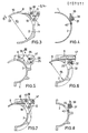
- Fig. 1 eine Längsansicht des Munitionsbehälters mit den Öffnungs- und Schließmechanismen von zwei Halteklammern;Figure 1 is a longitudinal view of the ammunition container with the opening and closing mechanisms of two retaining clips.
- Fig. 2 in einer Draufsicht II der Fig. 1 den Munitionsbehälter mit einer darin befindlichen und von den Halteklammern gehaltenen patronierten Munition;FIG. 2 shows a top view II of FIG. 1 the ammunition container with a cartridge ammunition located therein and held by the holding clips;
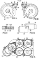
- Fig. 3 in einem Querschnitt entlang der in Fig. 1 mit III-III gekennzeichneten Fläche das Profil der Hüllenform des Munitionsbehälters im Bereich des Hülsenbodens mit Befestigungsanordnung einer Halteklammer;3 shows, in a cross section along the area marked III-III in FIG. 1, the profile of the casing shape of the ammunition container in the region of the casing base with a fastening arrangement of a holding clip;
- Fig. 4 in einem Querschnitt entlang der in Fig. 1 mit IV-IV gekennzeichneten Fläche die Befestigung der um eine Antriebswelle geuundenen Biegefeder in einem den Hülsenboden der patronierten Munition entsprechenden Bereich des Munitionsbehälters;Fig. 4 in a cross section along the area marked IV-IV in Fig. 1 the Be consolidation of the spiral spring wound around a drive shaft in an area of the ammunition container corresponding to the base of the cartridge of the cartridge;
- Fig. 5 in einem Querschnitt entlang der in Fig. 1 mit V-V gekennzeichneten Fläche eine im Durchmesser reduzierte Halbschalenform in einem dem Geschoßkopf der Munition zugeordneten Behälterbereich mit Anordnung eines auf verschiedenen Antriebswellen befestigten Öffnerhebels und eines Mitnehmers der Halteklammern;5 shows, in a cross section along the area marked V-V in FIG. 1, a reduced half-shell shape in a container area assigned to the projectile head of the ammunition, with an opening lever attached to different drive shafts and a driver of the retaining clips;
- Fig. 6 in einem Querschnitt entlang der in Fig. 1 mit VI-VI gekennzeichneten Fläche eine Halteklammer in geschlossener Halteposition und einen dabei zurückgezogenen und auf der Antriebswelle befestigten Munitionsauswerfer;6 shows a cross section along the area marked VI-VI in FIG. 1, a holding clip in the closed holding position and an ammunition ejector which is retracted and fastened to the drive shaft;
- Fig. 7 in einem Querschnitt entlang der in Fig. 1 mit VII-VII gekennzeichneten Fläche die Anordnung einer im Bereich des Geschoßkopfes der patronierten Munition befestigten Halteklammer;7 shows, in a cross section along the area marked VII-VII in FIG. 1, the arrangement of a retaining clip fastened in the area of the projectile head of the ammunition with cartridges;
- Fig. 8 in einem Querschnitt entlang der in Fig. 1 mit VIII-VIII gekennzeichneten Fläche die Befestigung der um eine Antriebswelle gewundenen Biegefeder in einem dem Geschoßkopf der patronierten Munition entsprechenden Bereich des Munitionsbehälters;8 shows, in a cross section along the surface identified by VIII-VIII in FIG. 1, the fastening of the spiral spring wound around a drive shaft in an area of the ammunition container corresponding to the projectile head of the ammunition with cartridges;
- Fig. 9 in einer in Fig. 1 mit IX gekennzeichneten Seitenansicht den Munitionsbehälter von der linken Seite;Fig. 9 in a marked in Fig. 1 with IX Side view of the ammunition container from the left side;
- Fig. 10 in einer in Fig. 1 mit X gekennzeichneten Seitenansicht den Munitionsbehälter von der rechten Seite;FIG. 10 shows the ammunition container from the right side in a side view marked X in FIG. 1;
- Fig. 11 in einer entlang der in Fig. 9 mit XI-XI gekennzeichneten Fläche einen Querschnitt durch eine Feineinstelleinrichtung;11 shows a cross section through a fine adjustment device along the area identified by XI-XI in FIG. 9;
- Fig. 12 in einer in Fig. 5 gekennzeichneten Ansicht XII den Öffnerhebel und den Mitnehmer in einer für beide Halteklammern bei dem Öffnungsvorgang vorhandenen Schleppstellung;FIG. 12, in a view XII marked in FIG. 5, the opening lever and the driver in a drag position present for both retaining clips during the opening process;
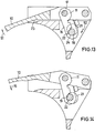
- Fig. 13 in einer vergrößerten ausschnittsweisen Darstellung der Fig. 3 die Halteklammer in einer durch den Öffnungs- und Schließmechanismus verriegelten Halteposition;FIG. 13 shows an enlarged, fragmentary illustration of FIG. 3, the holding clip in a holding position locked by the opening and closing mechanism;
- Fig. 14 entsprechend Fig. 13 die Halteklammer in einer durch den Öffnungs- und Schließmechanismus geöffneten Be- und Entladeposition;FIG. 14 corresponding to FIG. 13 the holding clip in a loading and unloading position opened by the opening and closing mechanism;
- Fig. 15 in einer Schnittdarstellung die Seitenansicht miteinander verbundener Munitionsbehälter als Teile eines Bandmagazins.Fig. 15 in a sectional view the side view of interconnected ammunition containers as parts of a tape magazine.
In den Figuren 1 und 2 ist der gesamte Munitionsbehälter 1 als Teil eines in Fig. 15 dargestellten Bandmagazins 35 einer nicht näher dargestellten automatischen Ladeeinrichtung für Rohrwaffen dargestellt. Der Munitionsbehälter 1 enthält nach den Figuren 3 bis 8 eine im Querschnitt halbkreisbogenförmig ausgebildete Schale 2, deren Innendurchmesser zur gleichmäßigen Aufnahme dünnwandiger patronierter Munition 3, vorzugsweise Kampfpanzermunition mit verbrennbarer Hülse, mehrfach abgesetzt ist. Die Abstützung der patronierten Munition 3 erfolgt einmal im Bereich 4 des Geschoßkopfes 5 und im Bereich 6 des Hülsenbodens 7. Entsprechend den unterschiedlichen Durchmessern des Geschoßkopfes 5 und des Hülsenbodens 7 ist der Innendurchmesser d1 der Förderschale 2 im Bereich 4 kleiner als der Innendurchmesser d2 im Bereich 6 ausgeführt. Zur Gewährleistung einer hohen Stabilität ist der Munitionsbehälter 1 im Aufnahmebereich 4 des vergleichsweise schweren Geschoßkopfes 5 im Außenbereich mit Verstärkungsrippen 42 versehen. Damit die Auflage der Munition 3 in den Bereichen des stabilen Hülsenbodens 7 und des Geschoßkopfes 5 erfolgen kann, ist in einer nicht dargestellten Weise der Munitionsbehälter 1 im Bereich einer verbrennbaren Treibladungshülse 41 hinterdreht ausgeführt. Auf beiden Stirnseiten 43, 44 enthält der Munitions behälter 1, als axiale Begrenzung der Munition 3, Stirnwände 45, 46, wobei die Stirnwand 45 als Losflansch über Schraubverbindungen nach der Lochbildanordnung-der Figur 10 und die Stirnwand 46 einstückig mit dem Munitionsbehälter 1 verbunden sind.In Figures 1 and 2, the entire ammunition container 1 is shown as part of a
Der Munitionsbehälter 1 ist in den Bereichen 4, 6 auf der gleichen Längsseite 8 mit zwei die patronierte Munition 3 in Umfangsrichtung teilweise umschließenden schwenkbaren Halteklammern 9, 10 ausgestattet. Die Halteklammer 9 ist dabei durch einen Öffnungs- und Schließmechanismus 12 um eine am Behälter 1 befestigte starre Achse 47 schwenkbar angeordnet, während die Halteklammer 10 durch einen Öffnungs- und Schließmechanismus 11 um eine am Behälter 1 befestigte starre Achse 48 schwenkbar angeordnet ist.In the
Der Öffnungs- und Schließmechanismus 11, 12 besteht im wesentlichen aus einem Hubhebel 16, der an einem Ende 17 drehbeweglich mit der Halteklammer 9, 10 verbunden ist und an dem anderen Ende 18 eine Bohrung 19 zur Aufnahme eines an einer Antriebswelle 20, 21 angeordneten Exzenters 22 enthält. Die Antriebswellen 20, 21 sind versetzt zueinander angeordnet und in den Bereichen der Halteklammern 9, 10 am Munitionsbehälter 1 gelagert, wobei die Welle 21 zusätzlich in einem Lager 50 im Bereich 4 gelagert ist.The opening and
Zum Ausüben einer jeweils individuellen und in den Bereichen 4, 6 voneinander unabhängigen radialen und spielfreien Haltefunktion, enthalten die Antriebswellen 20, 21 jeweils in Schließrichtung 15 drehmomenterzeugende mechanische Vorspannmittel 13, 14, die aus um die Antriebswellen 20, 21 gewundenen Biegefedern 37, 38 bestehen, deren Enden einerseits an einem Stift 39 der Antriebswellen 20, 21 und andererseits an einem am Munitionsbehälter 1 angeordneten Stift 40 befestigt sind.In order to perform an individual radial and play-free holding function that is independent of one another in the
Die einander zugekehrten Enden der Antriebswellen 20, 21 enthalten, gemäß Fig..5, 12, ankoppelbare Formschlußmittel 25, wobei das auf der Antriebswelle 20 angeordnete Formschlußmittel 25 als automatisch antreibbarer Öffnerhebel 26 ausgebildet ist und das auf der Antriebswelle 21 befindliche Formschlußmittel 25 als Mitnehmer 28 einen Ansatz 27 aufweist. Der Ansatz 27 des Mitnehmers 28 und der Öfffnerhebel 26 sind derartig zueinander angeordnet, daß nur während des Öffnungsvorganges der Halteklammern 9, 10 der Mitnehmer 28 in Schleppstellung 29 mit dem Öffnerhebel 26 verbunden ist. Dadurch sind beide Halteklammern 9, 10 über nur einen nicht dargestellten Öffnungsantrieb durch den Öffnerhebel 26 und die jeweiligen Öffnungs- und Schließmechanismen 11, 12 gleichmäßig aus einer die patronierte Munition 3 umschließenden Haltestellung 23 in Öffnungsrichtung 51 (Fig. 13) aufschwenkbar.The mutually facing ends of the
Nach Ausrasten des Öffnerhebels 26 aus dem externen Öffnungsantrieb gewährleistet der Ansatz 27 des Mitnehmers 28 einen separaten Rückhub der Halteklammern 9, 10 in Schließrichtung 15 (Fig. 14), so daß sich die Halteklammern 9, 10 den jeweilig vorhandenen Munitionsdurchmessern in den Bereichen 4, 6 anpassen können.After the
Wie Fig. 13 verdeutlicht, besteht in geschlossener Stellung 23 der Halteklammer 9, 10 zwischen dem Exzenter 22 und dem Hubhebel 16 eine in Schließrichtung 15 durch die Vorspannmittel 13, 14 unter Vorspannung stehende selbsthemmende Sicherstellung 24. Diese Sicherstellung 24 wird beim Öffnen der Halteklammern durch Drehen der Antriebswellen 20, 21 durch den Öffnerhebel 26 (Fig. 5) in Richtung 52 aufgehoben.As illustrated in FIG. 13, in the closed
Zur Grundeinstellung des Öffnerhebels 26 und des Mitnehmers 28 ist der Hubhebel 16, entsprechend Fig. 11, jeweils über eine Feineinstelleinrichtung 30 mit der Halteklammer 9, 10 verbunden. Die Feineinstelleinrichtung 30 besteht im wesentlichen aus einem in der Halteklammer 9, 10 geführten und im Führungsbereich des Hubhebels 16 als Exzenter 31 ausgebildeten Bolzen 49. Die Feineinstellung kann für jede Halteklammer 9, 10 stirnseitig von außen, auch im eingebauten Zustand des Munitionsbehälters 1,durchgeführt werden.For the basic setting of the
Damit die patronierte Munition schonend und gleichmäßig aus dem Behälter ausgestoßen werden kann, enthält jede Antriebswelle 20, 21 im Funktionsbereich der Halteklammern 9, 10 einen mit dem Hebel 33 ausgestatteten Munitionsauswerfer 32, wie er in Fig. 6 dargestellt ist.So that the ammunition can be ejected gently and evenly from the container, each
Wie Fig. 15 erkennen läßt, bilden die Munitionsbehälter 1 eine endlose Förderkette. Zur Bildung einer besonders flexiblen raumsparenden Kette ist jeder Munitionsbehälter 1 auf beiden Stirnseiten 43, 44 (Fig. 2) an den Tragbolzen 53 der Stirnwände 45, 46 (Fig. 2) mit dem nachfolgenden Munitionsbehälter 1 über Laschen 54 verbunden. Die Hüllenform 34 (Fig. 3) des Munitionsbehälters 1 ist im Bereich 6 (Fig. 2) des Hülsenbodens derartig ausgebildet, daß bei diesem waagerecht umlaufenden und in bekannter Weise angetriebenen sowie geführten Bandmagazin 35 die Halteklammer 9, 10 stets außenseitig entweder oberseitig oder unterseitig an dem Munitionsbehälter 1 angeordnet ist, wodurch waagerecht gelagerte und dünnwandig patronierte Munition 3 an dem hinteren nicht dargestellten Wendepunkt des Bandmagazins 35 bei geöffneter Halteklammer 9, 10 schräg von oben her aufnehmbar und an dem vorderen Wendepunkt 36 ebenfalls bei geöffneter Halteklammer 9, 10 schräg nach unten in eine Ladeschale 55 ausstoßbar ist.As can be seen in FIG. 15, the ammunition containers 1 form an endless conveyor chain. Each ammunition container is 1 to form a particularly flexible, space-saving chain on both
- 1 Munitionsbehälter1 ammunition container
- 2 Schale2 bowl
- 3 Munition3 ammunition
- 4 Bereich4 area
- 5 Geschoßkopf5 projectile head
- 6 Bereich6 area
- 7 Hülsenboden7 sleeve base
- 8 Längsseite8 long side
- 9 Halteklammer9 retaining clip
- 10 Halteklammer10 retaining clip
- 11 Öffnungs- und Schließmechanismus11 opening and closing mechanism
- 12 Öffnungs- und Schließmechanismus12 opening and closing mechanism
- 13 Vorspannmittel13 preloading means
- 14 Vorspannmittel14 preloading means
- 15 Schließrichtung15 closing direction
- 16 Hubhebel16 lifting lever
- 17 Ende17 end
- 18 Ende18 end
- 19 Aufnahmebohrung19 location hole
- 20 Antriebswelle20 drive shaft
- 21 Antriebswelle21 drive shaft
- 22 Exzenter22 eccentrics
- 23 Stellung23 position
- 24 Sicherstellung24 Freezing
- 25 Formschlußmittel25 positive locking means
- 26 Öffnerhebel26 opening lever
- 27 Ansatz27 approach
- 28 Mitnehmer28 drivers
- 29 Schleppstellung29 Drag position
- 30 Feineinstelleinrichtung30 fine adjustment device
- 31 Exzenter31 eccentrics
- 32 Munitionsauswerfer32 ammunition ejectors
- 33 Hebel33 levers
- 34 Hüllenform34 envelope shape
- 35 Bandmagazin35 tape magazine
- 36 Wendepunkt36 turning point
- 37 Biegefeder37 spiral spring
- 38 Biegefeder38 spiral spring
- 39 Stift39 pen
- 40 Stift40 pen
- 41 Hülse41 sleeve
- 42 Verstärkungsrippen42 reinforcing ribs
- 43 Stirnseite43 end face
- 44 Stirnseite44 end face
- 45 Stirnwand45 end wall
- 46 Stirnwand46 end wall
- 47 Achse47 axis
- 48 Achse48 axis
- 49 Bolzen49 bolts
- 50 Lager50 bearings
- 51 Öffnungsrichtung51 Opening direction
- 52 Richtung52 direction
- 53 Tragbolzen53 support bolts
- 54 Lasche54 tab
- 55 Ladeschale55 charging cradle
- d1 Innendurchmesserd 1 inner diameter
- d2 Innendurchmesserd 2 inner diameter
Claims (9)
Applications Claiming Priority (2)
| Application Number | Priority Date | Filing Date | Title |
|---|---|---|---|
| DE3409018 | 1984-03-13 | ||
| DE19843409018 DE3409018A1 (en) | 1984-03-13 | 1984-03-13 | AMMUNITION CONTAINER OF AN AUTOMATIC LOADING DEVICE |
Publications (2)
| Publication Number | Publication Date |
|---|---|
| EP0157111A1 true EP0157111A1 (en) | 1985-10-09 |
| EP0157111B1 EP0157111B1 (en) | 1987-05-13 |
Family
ID=6230242
Family Applications (1)
| Application Number | Title | Priority Date | Filing Date |
|---|---|---|---|
| EP85101124A Expired EP0157111B1 (en) | 1984-03-13 | 1985-02-04 | Ammunition container for an automatic loading mechanism |
Country Status (5)
| Country | Link |
|---|---|
| US (1) | US4619181A (en) |
| EP (1) | EP0157111B1 (en) |
| JP (1) | JPS60205200A (en) |
| DE (2) | DE3409018A1 (en) |
| ES (1) | ES8607528A1 (en) |
Cited By (3)
| Publication number | Priority date | Publication date | Assignee | Title |
|---|---|---|---|---|
| FR2619207A1 (en) * | 1987-08-03 | 1989-02-10 | Rheinmetall Gmbh | SHOP CHAIN FOR AMMUNITION RECEPTION |
| EP0783094A1 (en) * | 1996-01-05 | 1997-07-09 | Giat Industries | Device for the transfer of propulsive charges for a magazine to a loading device |
| FR2743413A1 (en) * | 1996-01-05 | 1997-07-11 | Giat Ind Sa | Storage and delivery system for artillery barrel charge modules |
Families Citing this family (17)
| Publication number | Priority date | Publication date | Assignee | Title |
|---|---|---|---|---|
| DE3612208C2 (en) * | 1986-04-11 | 1998-02-05 | Kuka Wehrtechnik Gmbh | Device for loading an armored weapon |
| JPH0663718B2 (en) * | 1986-04-25 | 1994-08-22 | 防衛庁技術研究本部長 | Ammo holder |
| US5227366A (en) * | 1987-08-07 | 1993-07-13 | The Clorox Company | Mitigation of stress-cracking in fragranced bleach-containing bottles |
| US4876940A (en) * | 1988-04-14 | 1989-10-31 | General Electric Company | Magazine ammunition conveying system |
| US4882972A (en) * | 1988-08-15 | 1989-11-28 | General Electric Company | Dual caliber ammunition handling system |
| US5131315A (en) * | 1990-12-24 | 1992-07-21 | General Electric Company | Magazine conveyor for large caliber ammunition |
| DE4126199C2 (en) * | 1991-08-08 | 1994-06-23 | Rheinmetall Gmbh | Ammunition container |
| US5175388A (en) * | 1991-12-23 | 1992-12-29 | General Electric Company | Ammunition bucket carriers for magazine conveyors |
| DE19529914C2 (en) * | 1994-11-29 | 2002-07-11 | Rheinmetall Landsysteme Gmbh | ammunition magazine |
| FR2765958B1 (en) * | 1997-07-11 | 1999-09-24 | Tda Armements Sas | MORTAR LOADING SYSTEM AND MORTAR EQUIPPED WITH SUCH A SYSTEM |
| US6073534A (en) * | 1998-01-14 | 2000-06-13 | General Dynamics Armament Systems, Inc. | Transfer mechanism and method for uploading and downloading propellant charges and projectiles |
| US6065385A (en) * | 1998-01-14 | 2000-05-23 | General Dynamics Armament Systems, Inc. | Bucket carrier for molded solid propellant storage magazine |
| JP6418862B2 (en) * | 2014-07-23 | 2018-11-07 | 有限会社マルゼン | Air gun cartridge |
| SE541259C2 (en) | 2016-06-21 | 2019-05-21 | Bae Systems Bofors Ab | System and method for loading ammunition to a primary magazine in an automatic gun |
| DE102020103813A1 (en) | 2020-02-13 | 2021-08-19 | Rheinmetall Air Defence Ag | Magazine of a cannon |
| SE545540C2 (en) * | 2020-08-18 | 2023-10-17 | Saab Ab | Spring arrangement for countermeasure magazine comprising it |
| DE102021117951A1 (en) * | 2021-07-12 | 2023-01-12 | Rheinmetall Air Defence Ag | Feeding device for loading and unloading a radially opening ammunition cup for an automatic gun loading system |
Citations (8)
| Publication number | Priority date | Publication date | Assignee | Title |
|---|---|---|---|---|
| FR727047A (en) * | 1931-01-29 | 1932-06-11 | Anciens Ets Sautter Harle | Improvements to norias for hoisting ammunition and other objects |
| US2460384A (en) * | 1944-05-25 | 1949-02-01 | United Shoe Machinery Corp | Gun-loading mechanism |
| US2933020A (en) * | 1957-11-20 | 1960-04-19 | Jr Edmond W Hammer | Tilt tray |
| US2972934A (en) * | 1951-05-11 | 1961-02-28 | Haviland H Platt | Continuous hoist for ammunition |
| DE2153327A1 (en) * | 1971-01-28 | 1972-08-03 | General Motors Corp., Detroit, Mich. (V.StA.) | Ammunition carriers |
| DE2501426A1 (en) * | 1974-01-15 | 1975-07-17 | Bofors Ab | LOADING DEVICE FOR A LARGE-CALIBER FIRE ARM |
| EP0083288A1 (en) * | 1981-12-24 | 1983-07-06 | Creusot-Loire | Ammunition feeding system for a gun |
| NL8103878A (en) * | 1980-08-19 | 1984-03-01 | Kuka Wehrtechnik Gmbh | HOLDER FOR RECORDING AND FEEDING A CARTRIDGE. |
Family Cites Families (2)
| Publication number | Priority date | Publication date | Assignee | Title |
|---|---|---|---|---|
| US2788713A (en) * | 1954-02-16 | 1957-04-16 | Even Georges | Armored vehicle |
| DE1301742B (en) * | 1966-01-26 | 1969-08-21 | Rheinmetall Gmbh | Magazine for guns built into armored domes |
-
1984
- 1984-03-13 DE DE19843409018 patent/DE3409018A1/en not_active Withdrawn
-
1985
- 1985-02-04 EP EP85101124A patent/EP0157111B1/en not_active Expired
- 1985-02-04 DE DE8585101124T patent/DE3560174D1/en not_active Expired
- 1985-02-13 ES ES540368A patent/ES8607528A1/en not_active Expired
- 1985-03-11 JP JP60046692A patent/JPS60205200A/en active Pending
- 1985-03-13 US US06/711,394 patent/US4619181A/en not_active Expired - Lifetime
Patent Citations (8)
| Publication number | Priority date | Publication date | Assignee | Title |
|---|---|---|---|---|
| FR727047A (en) * | 1931-01-29 | 1932-06-11 | Anciens Ets Sautter Harle | Improvements to norias for hoisting ammunition and other objects |
| US2460384A (en) * | 1944-05-25 | 1949-02-01 | United Shoe Machinery Corp | Gun-loading mechanism |
| US2972934A (en) * | 1951-05-11 | 1961-02-28 | Haviland H Platt | Continuous hoist for ammunition |
| US2933020A (en) * | 1957-11-20 | 1960-04-19 | Jr Edmond W Hammer | Tilt tray |
| DE2153327A1 (en) * | 1971-01-28 | 1972-08-03 | General Motors Corp., Detroit, Mich. (V.StA.) | Ammunition carriers |
| DE2501426A1 (en) * | 1974-01-15 | 1975-07-17 | Bofors Ab | LOADING DEVICE FOR A LARGE-CALIBER FIRE ARM |
| NL8103878A (en) * | 1980-08-19 | 1984-03-01 | Kuka Wehrtechnik Gmbh | HOLDER FOR RECORDING AND FEEDING A CARTRIDGE. |
| EP0083288A1 (en) * | 1981-12-24 | 1983-07-06 | Creusot-Loire | Ammunition feeding system for a gun |
Cited By (5)
| Publication number | Priority date | Publication date | Assignee | Title |
|---|---|---|---|---|
| FR2619207A1 (en) * | 1987-08-03 | 1989-02-10 | Rheinmetall Gmbh | SHOP CHAIN FOR AMMUNITION RECEPTION |
| EP0783094A1 (en) * | 1996-01-05 | 1997-07-09 | Giat Industries | Device for the transfer of propulsive charges for a magazine to a loading device |
| FR2743411A1 (en) * | 1996-01-05 | 1997-07-11 | Giat Ind Sa | DEVICE FOR TRANSFERRING MODULES CONSTITUTING PROPULSIVE LOADS BETWEEN A STORAGE STORE AND A SYSTEM FOR LOADING THESE MODULES IN THE CHAMBER OF AN ARTILLERY GUN |
| FR2743413A1 (en) * | 1996-01-05 | 1997-07-11 | Giat Ind Sa | Storage and delivery system for artillery barrel charge modules |
| US5837923A (en) * | 1996-01-05 | 1998-11-17 | Giat Industries | Transfer device for transferring modules constituting propellant charges between a storage magazine and a system for loading the modules into the chamber of a large-caliber gun barrel |
Also Published As
| Publication number | Publication date |
|---|---|
| JPS60205200A (en) | 1985-10-16 |
| ES540368A0 (en) | 1986-06-01 |
| DE3409018A1 (en) | 1985-09-26 |
| ES8607528A1 (en) | 1986-06-01 |
| EP0157111B1 (en) | 1987-05-13 |
| DE3560174D1 (en) | 1987-06-19 |
| US4619181A (en) | 1986-10-28 |
Similar Documents
| Publication | Publication Date | Title |
|---|---|---|
| EP0157111B1 (en) | Ammunition container for an automatic loading mechanism | |
| EP0178484B1 (en) | Loading device for ordnances | |
| DE1938681C3 (en) | Magazine for guns built into armored turrets, especially armored vehicles | |
| EP0303761B1 (en) | Arrangement in a rapid fire weapon with an external motor for ejecting cartridge cases forwards | |
| DE2414332C3 (en) | Loading device, in particular for a nail gun | |
| DE3041866C2 (en) | Device for transporting ammunition from an ammunition container for locking a weapon | |
| DE2501424C2 (en) | Ammunition receiving and loading device for a large-caliber firearm | |
| EP0557751B1 (en) | Howitzer with pivotable loading arm and ammunition magazine of the endless-chain type | |
| DE3642920C2 (en) | Loading device for a combat vehicle, in particular a self-propelled howitzer | |
| DE3702603A1 (en) | CHARGING SYSTEM FOR CARTRIDGED AMMUNITION CONTAINERS | |
| EP1098159B1 (en) | Device for connecting a cartridge magazine to a magazine support in an automatic gun | |
| EP1736726B1 (en) | Loading system for propellant charges | |
| DE19913283C2 (en) | Loading device for a large caliber weapon | |
| DE3701713C2 (en) | ||
| DE3702426C2 (en) | ||
| EP0754926A2 (en) | Turret for a wheeled or tracked vehicle | |
| EP0356616B1 (en) | Turret magazine | |
| DE3219800C2 (en) | Device for feeding ammunition to a machine gun | |
| EP3865811A1 (en) | Magazine of a gun | |
| DE4126199C2 (en) | Ammunition container | |
| DE1728134A1 (en) | Device for the delivery of objects, especially for automatic weapons | |
| CH626162A5 (en) | Loading device, which is intended for loading a projectile or a propulsion charge, on a gun | |
| DE3733214A1 (en) | Combat equipment | |
| DE3343843C2 (en) | ||
| DE102020104465B3 (en) | magazine |
Legal Events
| Date | Code | Title | Description |
|---|---|---|---|
| PUAI | Public reference made under article 153(3) epc to a published international application that has entered the european phase |
Free format text: ORIGINAL CODE: 0009012 |
|
| AK | Designated contracting states |
Designated state(s): CH DE FR GB LI SE |
|
| 17P | Request for examination filed |
Effective date: 19850816 |
|
| 17Q | First examination report despatched |
Effective date: 19860806 |
|
| GRAA | (expected) grant |
Free format text: ORIGINAL CODE: 0009210 |
|
| AK | Designated contracting states |
Kind code of ref document: B1 Designated state(s): CH DE FR GB LI SE |
|
| REF | Corresponds to: |
Ref document number: 3560174 Country of ref document: DE Date of ref document: 19870619 |
|
| ET | Fr: translation filed | ||
| PLBE | No opposition filed within time limit |
Free format text: ORIGINAL CODE: 0009261 |
|
| STAA | Information on the status of an ep patent application or granted ep patent |
Free format text: STATUS: NO OPPOSITION FILED WITHIN TIME LIMIT |
|
| 26N | No opposition filed | ||
| PGFP | Annual fee paid to national office [announced via postgrant information from national office to epo] |
Ref country code: CH Payment date: 19890125 Year of fee payment: 5 |
|
| PG25 | Lapsed in a contracting state [announced via postgrant information from national office to epo] |
Ref country code: CH Effective date: 19900228 Ref country code: LI Effective date: 19900228 |
|
| REG | Reference to a national code |
Ref country code: CH Ref legal event code: PL |
|
| PGFP | Annual fee paid to national office [announced via postgrant information from national office to epo] |
Ref country code: SE Payment date: 19930118 Year of fee payment: 9 |
|
| PG25 | Lapsed in a contracting state [announced via postgrant information from national office to epo] |
Ref country code: SE Effective date: 19940205 |
|
| EUG | Se: european patent has lapsed |
Ref document number: 85101124.7 Effective date: 19940910 |
|
| PGFP | Annual fee paid to national office [announced via postgrant information from national office to epo] |
Ref country code: GB Payment date: 20010112 Year of fee payment: 17 |
|
| PGFP | Annual fee paid to national office [announced via postgrant information from national office to epo] |
Ref country code: FR Payment date: 20010205 Year of fee payment: 17 Ref country code: DE Payment date: 20010205 Year of fee payment: 17 |
|
| REG | Reference to a national code |
Ref country code: GB Ref legal event code: IF02 |
|
| PG25 | Lapsed in a contracting state [announced via postgrant information from national office to epo] |
Ref country code: GB Free format text: LAPSE BECAUSE OF NON-PAYMENT OF DUE FEES Effective date: 20020204 |
|
| PG25 | Lapsed in a contracting state [announced via postgrant information from national office to epo] |
Ref country code: DE Free format text: LAPSE BECAUSE OF NON-PAYMENT OF DUE FEES Effective date: 20020903 |
|
| GBPC | Gb: european patent ceased through non-payment of renewal fee |
Effective date: 20020204 |
|
| PG25 | Lapsed in a contracting state [announced via postgrant information from national office to epo] |
Ref country code: FR Free format text: LAPSE BECAUSE OF NON-PAYMENT OF DUE FEES Effective date: 20021031 |
|
| REG | Reference to a national code |
Ref country code: FR Ref legal event code: ST |