EP0135639A1 - Apparatus for improving the operational characteristics of a heating appliance with submerged combustion - Google Patents
Apparatus for improving the operational characteristics of a heating appliance with submerged combustion Download PDFInfo
- Publication number
- EP0135639A1 EP0135639A1 EP83401863A EP83401863A EP0135639A1 EP 0135639 A1 EP0135639 A1 EP 0135639A1 EP 83401863 A EP83401863 A EP 83401863A EP 83401863 A EP83401863 A EP 83401863A EP 0135639 A1 EP0135639 A1 EP 0135639A1
- Authority
- EP
- European Patent Office
- Prior art keywords
- installation
- air
- plant
- programmer
- ignition
- Prior art date
- Legal status (The legal status is an assumption and is not a legal conclusion. Google has not performed a legal analysis and makes no representation as to the accuracy of the status listed.)
- Granted
Links
Images
Classifications
-
- F—MECHANICAL ENGINEERING; LIGHTING; HEATING; WEAPONS; BLASTING
- F23—COMBUSTION APPARATUS; COMBUSTION PROCESSES
- F23C—METHODS OR APPARATUS FOR COMBUSTION USING FLUID FUEL OR SOLID FUEL SUSPENDED IN A CARRIER GAS OR AIR
- F23C3/00—Combustion apparatus characterised by the shape of the combustion chamber
- F23C3/004—Combustion apparatus characterised by the shape of the combustion chamber the chamber being arranged for submerged combustion
-
- F—MECHANICAL ENGINEERING; LIGHTING; HEATING; WEAPONS; BLASTING
- F23—COMBUSTION APPARATUS; COMBUSTION PROCESSES
- F23M—CASINGS, LININGS, WALLS OR DOORS SPECIALLY ADAPTED FOR COMBUSTION CHAMBERS, e.g. FIREBRIDGES; DEVICES FOR DEFLECTING AIR, FLAMES OR COMBUSTION PRODUCTS IN COMBUSTION CHAMBERS; SAFETY ARRANGEMENTS SPECIALLY ADAPTED FOR COMBUSTION APPARATUS; DETAILS OF COMBUSTION CHAMBERS, NOT OTHERWISE PROVIDED FOR
- F23M11/00—Safety arrangements
-
- F—MECHANICAL ENGINEERING; LIGHTING; HEATING; WEAPONS; BLASTING
- F24—HEATING; RANGES; VENTILATING
- F24H—FLUID HEATERS, e.g. WATER OR AIR HEATERS, HAVING HEAT-GENERATING MEANS, e.g. HEAT PUMPS, IN GENERAL
- F24H1/00—Water heaters, e.g. boilers, continuous-flow heaters or water-storage heaters
- F24H1/10—Continuous-flow heaters, i.e. heaters in which heat is generated only while the water is flowing, e.g. with direct contact of the water with the heating medium
- F24H1/107—Continuous-flow heaters, i.e. heaters in which heat is generated only while the water is flowing, e.g. with direct contact of the water with the heating medium using fluid fuel
Definitions
- the present invention relates to a method and an installation making it possible to improve the operating characteristics of a heating installation of the submerged combustion type.
- the combustion chamber having a relatively high thermal inertia, and being able to be brought during combustion to temperatures close to 1000 ° C., difficulties appear between each operating cycle as a result of rising water in the combustion chamber still hot after post-sweeping, leading to significant thermal constraints of the chamber, which can cause cracks and rising steam and humid air throughout the installation, which can disturb the proper functioning of the electrical components, in particular the ignition .
- the object of the invention is to avoid the abovementioned drawbacks.
- the process according to the invention is characterized in that, after controlled burner shutdown, the air ventilation of the installation is maintained at least for a sufficiently long time, for example of the order several minutes, to cool down to a temperature close to or below 100 ° C of the walls of the combustion chamber.
- the method is simply implemented by controlling the supply of pressurized combustion air independently of the programmer, as soon as the installation is energized, by means of a timed opening relay supplied by the system energizing circuit and which closes as soon as the system is started up.
- a timed opening relay supplied by the system energizing circuit and which closes as soon as the system is started up.
- the installation further comprises, on the air blowing circuit for combustion, a bypass circuit which blows air on the spark plugs or the like and which is controlled by a solenoid valve. from a time-delayed relay energized by the programmer at the start of each ignition cycle. In this way, at the start of each ignition cycle, and before ignition is controlled by switching on the spark plugs, dry combustion air is blown on the spark plug electrodes, eliminating of these electrodes any trace of humidity, thus ensuring a trouble-free start of the cycle.
- the installation comprises a burner 1, of the jet or other type which develops a vertical flame 2 directed downwards in a hearth 3 constituting the combustion chamber whose wall is usually metallic made up of one or more layers.
- the products or gases of combustion escape in the form of bubbles 4 through holes 5 formed at the bottom of the chamber 3 directly in the bath to be heated 30, usually consisting of water contained in a suitable container or enclosure 31 and below level 15 of the bath.
- the operating cycle (ignition and extinction) of the burner is controlled by an approved programmer 6 which must meet precise specifications defined by the Public authorities.
- This programmer 6 gives orders to the motor 7 of a combustion air fan, checks the presence of the suitable air pressure measured in 8 and the suitable gas pressure measured in 9 and sends an ignition order by l 'through a high voltage transformer 10 to a spark plug 11; the programmer also gives orders to the air 12 and gas 13 solenoid valves and checks the presence of the flame by a detection member 14.
- the programmer pre-scans the installation, i.e. scans the entire combustion chamber 3 with air only, with the air pressure in front be greater than the hydrostatic pressure of the liquid contained in the bath 30. This pre-sweep time is of the order of a minute. Then, if the air and gas pressures are suitable, the programmer 6 controls the supply of the ignition transformer 10 and the burner ignites.
- the programmer 6 closes the solenoid valve 13 of the fuel and performs a post-scan, that is to say a post ventilation of the equipment while continuing to send air through the fan 7 throughout the installation for a time of the order of 30 seconds.
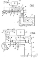
- FIG. 2 showing the modified installation in accordance with the invention and in which the same references have been used to identify identical parts.
- the starting of the fan motor 7 is no longer controlled by the junction 27 coming from the programmer 6, but directly by a junction 21 connected to the current supply line of the installation, it even controlled by a relay 19, the contact 18 of which is timed on opening, the relay 19 being itself supplied through the on / off button 20 of the installation.
- the motor 7 will remain supplied by the line 21 for the time of the time delay of the contact 18 and will ensure the necessary cooling of the wall of the combustion chamber 3.
- the time delay will be sufficient to ensure that the temperature of the internal wall of the chamber 3 will not be substantially greater than 100 ° C; with conventional power installations, this time delay may be of the order of approximately 8 to 10 minutes.
- the electrodes 17 of the spark plug 11 will be blown into the air through a tube 22 supplied by means of a bypass solenoid valve 23 on the main air supply circuit 29 of the fan.
- the solenoid valve 23 is supplied from the programmer junction 27 which was initially used to control the start-up of the fan in pre and post-sweeps.
- the supply of the solenoid valve 23 is also done through the contact 24 of a relay 25 supplied by the junction 27 and delayed on closing.
- the time delay may be approximately 30 seconds, corresponding to the pre-sweep time.
Abstract
Description
La présente invention concerne un procédé et une installation permettant d'améliorer les caractéristiques de fonctionnement d'une installation de chauffage du type à combustion submergée.The present invention relates to a method and an installation making it possible to improve the operating characteristics of a heating installation of the submerged combustion type.
Pour diverses applications, notamment de chauffage industriel, de chauffage de piscines et autres, on utilise parfois des installations utilisant des brûleurs à combustion submergée.For various applications, in particular industrial heating, swimming pool heating and others, installations using submerged combustion burners are sometimes used.
L'intérêt de telles installations est que l'on récupère, du fait du barbotage des gaz de combustion dans l'eau à chauffer, la plus grande partie de la chaleur latente de condensation des fumées. Ceci permet d'obtenir des rendements calculés sur le pouvoir calorifique inférieur (PCI) supérieur à 100% et fréquemment de l'ordre de 105%.The advantage of such installations is that, due to the bubbling of the combustion gases in the water to be heated, most of the latent heat of condensation of the fumes is recovered. This makes it possible to obtain yields calculated on the lower calorific value (PCI) greater than 100% and frequently of the order of 105%.
Cette technique séduisante présente cependant un certain nombre de difficultés inhérentes au principe même de la combustion qui s'effectue en milieu submergé. L'installation doit utiliser une arrivée de combustible (gaz ou fuel par exemple), une arrivée d'air comburant pressurisé par un ventilateur ou analogue, un dispositif d'allumage automatique à bougie ou analogue et un programmateur qui commandera successivement et automatiquement aux moments opportuns l'arrivée de combustible, l'allumage des brûleurs et l'arrêt d'alimentation de combustible lorsque la température de fonctionnement désirée aura été atteinte. Les brûleurs fonctionnant dans une chambre de combustion close, submergée,il est nécessaire pour des questions de sécurité et afin d'éviter tout risque d'explosion de réaliser avant allumage et après extinction des brûleurs respectivement un pré-balayage et un post-balayage à l'air de la chambre. Ces cycles sont pris en charge par le programmateur.This attractive technique however presents a certain number of difficulties inherent in the very principle of combustion which takes place in a submerged environment. The installation must use a fuel supply (gas or fuel for example), a supply of combustion air pressurized by a fan or the like, an automatic spark-ignition device or the like and a programmer which will control successively and automatically at times the fuel supply, the ignition of the burners and the fuel supply stop when the desired operating temperature has been reached. The burners operating in a closed, submerged combustion chamber, it is necessary for safety reasons and in order to avoid any risk of explosion to carry out before ignition and after extinction of the burners respectively a pre-sweep and a post-sweep with the air of the room. These cycles are taken care of by the programmer.
Cependant, la chambre de combustion ayant une inertie thermique relativement importante, et pouvant être portée lors de la combustion à des températures voisines de 1000°C, il apparaît des difficultés entre chaque cycle de fonctionnement par suite de remontées de l'eau dans la chambre de combustion encore chaude après post-balayage, conduisant a aes contraintes thermiques importantes de la chambre pouvant engendrer des fissures et des remontées de vapeur et d'air humide dans toute l'installation pouvant perturber le bon fonctionnement des organes électriques notamment d'allumage.However, the combustion chamber having a relatively high thermal inertia, and being able to be brought during combustion to temperatures close to 1000 ° C., difficulties appear between each operating cycle as a result of rising water in the combustion chamber still hot after post-sweeping, leading to significant thermal constraints of the chamber, which can cause cracks and rising steam and humid air throughout the installation, which can disturb the proper functioning of the electrical components, in particular the ignition .
L'invention a pour objet d'éviter les inconvénients susmentionnés.The object of the invention is to avoid the abovementioned drawbacks.
A cet effet le procédé conforme à l'invention se carac- caractérise en ce qu'on maintient après arrêt commandé des brûleurs, la ventilation à l'air de l'installation au moins pendant un temps suffisamment long,par exemple de l'ordre de plusieurs minutes, pour assurer le refroidissement jusqu'à une température voisine ou inférieure à 100°.C des parois de la chambre de combustion. Ainsi, on évite radicalement le problème des contraintes dues à un refroidissement brutal par remontée d'eau dans la chambre de combustion et la production simultanée de vapeur d'eau néfaste au bon fonctionnement.To this end, the process according to the invention is characterized in that, after controlled burner shutdown, the air ventilation of the installation is maintained at least for a sufficiently long time, for example of the order several minutes, to cool down to a temperature close to or below 100 ° C of the walls of the combustion chamber. Thus, the problem of stresses due to sudden cooling by rising water in the combustion chamber and the simultaneous production of water vapor detrimental to proper operation is radically avoided.
Selon un mode de réalisation préféré, le procédé est simplement mis en oeuvre en commandant l'arrivée d'air comburant pressurisé indépendamment du programmateur, dès que l'installation est mise sous tension, par l'intermédiaire d'un relais à ouverture temporisée alimenté par le circuit de mise sous tension de l'installation et qui se ferme dès la mise en route de l'installation. Ainsi,la circulation d'air comburant sera maintenu en permanence dans l'installation, et lorsqu'on arrêtera l'installation, par exemple en fin de journée si le cycle d'utilisation est diurne, le relais à ouverture temporisé maintiendra dans l'installation la circulation d'air comburant suffisamment longtemps pour assurer le bon refroidissement de la chambre.According to a preferred embodiment, the method is simply implemented by controlling the supply of pressurized combustion air independently of the programmer, as soon as the installation is energized, by means of a timed opening relay supplied by the system energizing circuit and which closes as soon as the system is started up. Thus, the combustion air circulation will be maintained permanently in the installation, and when the installation is stopped, for example at the end of the day if the duty cycle is daytime, the time-delayed relay will maintain in the installation the combustion air circulation long enough to ensure proper cooling of the chamber.
Selon une autre caractéristique avantageuse de l'invention, l'installation comprend en outre sur le circuit de soufflage d'air comburant un circuit de dérivation qui souffle de l'air sur les bougies d'allumage ou analogues et qui est commandé par une électrovanne à partir d'un relais à fermeture temporisée mis sous tension par le programmateur à chaque début d'un cycle d'allumage. De cette façon, à la mise en route de chaque cycle d'allumage, et avant que l'allumage soit commandé par mise sous tension des bougies, de l'air sec comburant est soufflé sur les électrodes de la bougie, éliminant de ces électrodes toute trace d'humidité, assurant ainsi un démarrage sans problème du cycle.According to another advantageous characteristic of the invention, the installation further comprises, on the air blowing circuit for combustion, a bypass circuit which blows air on the spark plugs or the like and which is controlled by a solenoid valve. from a time-delayed relay energized by the programmer at the start of each ignition cycle. In this way, at the start of each ignition cycle, and before ignition is controlled by switching on the spark plugs, dry combustion air is blown on the spark plug electrodes, eliminating of these electrodes any trace of humidity, thus ensuring a trouble-free start of the cycle.
L'invention apparaîtra plus clairement à l'aide de description qui va suivre faite en référence aux dessins annexés dans lesquels :
- - la figure 1 montre un schéma d'une installation classique à combustion submergée;
- - la figure 2 montre un schéma de la même installation mais comportant les modifications objets de perfectionnements de l'invention.
- - Figure 1 shows a diagram of a conventional submerged combustion installation;
- - Figure 2 shows a diagram of the same installation but comprising the modifications subject to improvements of the invention.
On décrira tout d'abord une installation classique telle qu'elle se présente comme illustrée à la figure 1.Firstly, a conventional installation will be described as it appears as illustrated in FIG. 1.
L'installation comprend un brûleur 1, du type jet ou autre qui développe une flamme 2 verticale dirigée vers le bas dans un foyer 3 constituant la chambre de combustion dont la paroi est habituellement métallique constituée d'une ou plusieurs couches. Les produits ou gaz de la combustion s'échappent sous forme de bulles 4 par des trous 5 formés en bas de la chambre 3 directement dans le bain à chauffer 30, habituellement constitué par de l'eau contenue dans un récipient ou une enceinte convenable 31 et en dessous du niveau 15 du bain.The installation comprises a
Le cycle de fonctionnement (allumage et extinction) du brûleur est commandé par un programmateur 6 agréé devant répondre à des spécifications précises définies par les Pouvoirs Publics. Ce programmateur 6 donne des ordres au moteur 7 d'un ventilateur d'air comburant, vérifie la présence de la pression d'air convenable mesurée en 8 et de la pression de gaz convenable mesurée en 9 et envoie un ordre d'allumage par l'intermédiaire d'un transformateur haute tension 10 à une bougie d'allumage 11; le programmateur donne également des ordres aux électrovannes d'air 12 et de gaz 13 et vérifie la présence de la flamme par un organe de détection 14.The operating cycle (ignition and extinction) of the burner is controlled by an approved
Au début du cycle, le programmateur procède à un pré-balayage de l'installation, c'est-à-dire au balayage par l'air uniquement de l'ensemble de la chambre de combustion 3, la pression de l'air devant être supérieure à la pression hydrostatique du liquide contenu dans le bain 30. Ce temps de pré-balayage est de l'ordre de la minute. Ensuite, si les pressions d'air et de gaz sont convenables, le programmateur 6 commande l'alimentation du transformateur d'allumage 10 et le brûleur s'allume.At the start of the cycle, the programmer pre-scans the installation, i.e. scans the
En fin de cycle, c'est-à-dire lorsque le bain 30 a atteint la température désirée, le programmateur 6 ferme l'électrovanne 13 du combustible et procède à un post-balayage, c'est-à-dire à une post-ventilation de l'équipement en continuant à envoyer de l'air par le ventilateur 7 dans l'ensemble de l'installation pendant un temps de l'ordre de 30 secondes.At the end of the cycle, that is to say when the
Cette façon de faire, si elle est conforme aux spécifications en vigueur dans la plupart des pays et valable pour des chaudières, présente pour l'utilisation spécifique du chauffage en direct par des produits de combustion les inconvénients suivants :
- - lors de l'arrêt de l'installation, le liquide du
bain 30 remonte trop rapidement à l'intérieur de lachambre 3. Le métal porté sur sa face interne à une température de l'ordre de 1000°C est brutalement refroidi, ce qui crée des contraintes thermiques importantes et détériore ses qualités pouvant entraîner des fissures.De plus, cela provoque une vaporisation du liquide créant une tension de vapeur qui chemine jusqu'aux électrovannes d'air 12 et degaz 13 et aux membranes de prise depression 8 et 9. Cette pression de vapeur risque également d'atteindre leventilateur 7. La vapeur qui est à une température supérieure à 100°C détériore ainsi les organes précédemment cités qui sont la plupart du temps conçus pour des températures de fonctionnement ne dépassant pas 50°C et qui s'accommodent mal d'une humidité importante. - - lors de la régulation de l'installation, c'est-à-dire lors de l'arrêt momentané entre deux cycles de fonctionnement de l'installation lorsque le bain n'a pas besoin de chaleur (l'installation fonctionnant par tout ou rien) les problèmes sont identiques, puisque le programmateur procède au post-balayage comme indiqué ci-dessus et attend un ordre deIa sonde de température pour commander un autre démarrage. Autrement dit, entre deux cycles de fonctionnement successifs, on retrouve les inconvénients susmentionnés existant à la suite de la mise à l'arrêt de l'installation.
- - l'allumage est incertain, car l'installation étant à l'arrêt définitif en fin de travail, une atmosphère humide règne dans l'enceinte 16 de la partie supérieure de la
chambre 3, et lesélectrodes 17 de labougie 11 sont humides. L'installation risque de ne pas s'allumer, créant ainsi une gêne auprès de l'utilisateur. Cet inconvénient existe également lors du fonctionnement normal entre deux cycles.
- when the installation is stopped, the liquid from the
bath 30 rises too quickly inside thechamber 3. The metal brought to its internal face at a temperature of the order of 1000 ° C. is suddenly cooled, This creates significant thermal stresses and deteriorates its qualities which can cause cracks. In addition, this causes vaporization of the liquid creating a vapor pressure which travels to theair 12 andgas 13 solenoid valves and the intake membranes.pressure fan 7. The vapor which is at a temperature above 100 ° C. thus deteriorates the above-mentioned members which are most of the time designed for operating temperatures not exceeding not 50 ° C and which do not adapt well to high humidity. - - during the regulation of the installation, that is to say during the temporary stop between two operating cycles of the installation when the bath does not need heat (the installation functioning by all or nothing) the problems are identical, since the programmer carries out the post-scan as indicated above and waits for an order from the temperature probe to order another start. In other words, between two successive operating cycles, there are the aforementioned drawbacks existing at the following the shutdown of the installation.
- - the ignition is uncertain, because the installation being at the final stop at the end of work, a humid atmosphere prevails in the
enclosure 16 of the upper part of thechamber 3, and theelectrodes 17 of thespark plug 11 are wet . The installation may not light up, creating discomfort for the user. This drawback also exists during normal operation between two cycles.
On se reportera maintenant à la figure 2 montrant l'installation modifiée conforme à l'invention et dans laquelle les mêmes repères ont été utilisés pour repérer les pièces identiques.Reference will now be made to FIG. 2 showing the modified installation in accordance with the invention and in which the same references have been used to identify identical parts.
Conformément à l'invention, la mise en route du moteur 7 du ventilateur n'est plus commandée par la jonction 27 provenant du programmateur 6, mais directement par une jonction 21 reliée à la ligne d'alimentation en courant de l'installation, elle-même commandée par un relais 19 dont le contact 18 est temporisé à l'ouverture, le relais 19 étant lui-même alimenté à travers le bouton marche/arrêt 20 de l'installation.According to the invention, the starting of the
Il apparaît ainsi que tant que le bouton marche/ arrêt 20 sera fermé, le moteur 7 du ventilateur sera alimenté assurant la mise sous pression d'air de l'installation, et évitant par conséquent radicalement toute remontée de liquide du bain 30 dans la chambre de combustion 3.It thus appears that as long as the on / off
En outre, lors de l'arrêt de l'installation, par exemple en fin de journée, c'est-à-dire à l'ouverture du bouton marche/arrêt 20, le moteur 7 restera alimenté par la ligne 21 le temps de la temporisation du contact 18 et assurera le refroidissement nécessaire de la paroi de la chambre de combustion 3. La durée de temporisation sera suffisante pour assurer que la température de la paroi interne de la chambre 3 ne sera pas sensiblement supérieure à 100°C; avec des installations de puissance classique, cette durée de temporisation pourra être de l'ordre de 8 à 10 mn environ. Ainsi, on assure la marche permanente du ventilateur 7 lorsque l'installation est sous tension, et le post-balayage en fin de travail pendant un temps suffisant, tout en utilisant un programmateur agréé assurant des temps de sécurité imposés par les spécifications et ne nécessitant aucune modification importante de l'installation..In addition, when the installation is stopped, for example at the end of the day, that is to say when the on / off
En ce qui concerne la sûreté de l'allumage, et selon une autre caractéristique de l'invention, on soufflera les électrodes 17 de la bougie 11 à l'air à travers un tube 22alimenté par l'intermédiaire d'une électrovanne 23 en dérivation sur le circuit de soufflage d'air principal 29 du ventilateur.With regard to ignition safety, and according to another characteristic of the invention, the
Dans l'exemple illustré de commande, l'électrovanne 23 est alimentée à partir de la jonction 27 di programmateur qui servait initialement à commander la mise en route du ventilateur en pré et post-balayages. L'alimentation de l'électrovanne 23 se fait en outre à travers le contact 24 d'un relais 25 alimenté par la jonction 27 et temporisé à la fermeture. La temporisation pourra être de 30 secondes environ, correspondant au temps de pré-balayage. Par cette disposition, les électrodes 17 de la bougie 11 sont soufflées et débarrassées de leur humidité avant l'alimentation du transformateur 10, et ce à chaque cycle d'allumage. De cette manière, on évite non seulement à l'origine la production de vapeur d'eau dans la partie supérieure 16 de la chambre de combustion, mais on débarrasse également efficacement les électrodes 17 de toute trace d'humidité au début de chaque cycle d'allumage.In the illustrated control example, the
Claims (5)
Priority Applications (2)
| Application Number | Priority Date | Filing Date | Title |
|---|---|---|---|
| DE8383401863T DE3379592D1 (en) | 1983-09-23 | 1983-09-23 | Apparatus for improving the operational characteristics of a heating appliance with submerged combustion |
| EP19830401863 EP0135639B1 (en) | 1983-09-23 | 1983-09-23 | Apparatus for improving the operational characteristics of a heating appliance with submerged combustion |
Applications Claiming Priority (1)
| Application Number | Priority Date | Filing Date | Title |
|---|---|---|---|
| EP19830401863 EP0135639B1 (en) | 1983-09-23 | 1983-09-23 | Apparatus for improving the operational characteristics of a heating appliance with submerged combustion |
Publications (2)
| Publication Number | Publication Date |
|---|---|
| EP0135639A1 true EP0135639A1 (en) | 1985-04-03 |
| EP0135639B1 EP0135639B1 (en) | 1989-04-12 |
Family
ID=8191444
Family Applications (1)
| Application Number | Title | Priority Date | Filing Date |
|---|---|---|---|
| EP19830401863 Expired EP0135639B1 (en) | 1983-09-23 | 1983-09-23 | Apparatus for improving the operational characteristics of a heating appliance with submerged combustion |
Country Status (2)
| Country | Link |
|---|---|
| EP (1) | EP0135639B1 (en) |
| DE (1) | DE3379592D1 (en) |
Cited By (2)
| Publication number | Priority date | Publication date | Assignee | Title |
|---|---|---|---|---|
| CN109990273A (en) * | 2019-04-30 | 2019-07-09 | 无锡特莱姆气体设备有限公司 | Submerged combustion gasifier burner and its combustion control system |
| CN111189230A (en) * | 2018-11-15 | 2020-05-22 | 青岛经济技术开发区海尔热水器有限公司 | Automatic control method of gas water heater and gas water heater |
Citations (7)
| Publication number | Priority date | Publication date | Assignee | Title |
|---|---|---|---|---|
| US2118479A (en) * | 1938-03-24 | 1938-05-24 | Submerged Comb Company Of Amer | Submerged combustion burner |
| US2375840A (en) * | 1941-12-23 | 1945-05-15 | Elematic Corp | Liquid heating apparatus |
| US2767784A (en) * | 1951-03-22 | 1956-10-23 | Ind Systems Inc | Fuel burner |
| FR1439336A (en) * | 1965-05-03 | 1966-05-20 | Mere Ind | Heating or combustion devices |
| FR1503119A (en) * | 1965-12-02 | 1967-11-24 | Hanrez Sa J Atel | Submerged combustion heater |
| FR2195326A5 (en) * | 1972-08-04 | 1974-03-01 | Aquitaine Petrole | |
| US4122557A (en) * | 1977-07-29 | 1978-10-31 | Harris Frank N | Incinerator |
-
1983
- 1983-09-23 EP EP19830401863 patent/EP0135639B1/en not_active Expired
- 1983-09-23 DE DE8383401863T patent/DE3379592D1/en not_active Expired
Patent Citations (7)
| Publication number | Priority date | Publication date | Assignee | Title |
|---|---|---|---|---|
| US2118479A (en) * | 1938-03-24 | 1938-05-24 | Submerged Comb Company Of Amer | Submerged combustion burner |
| US2375840A (en) * | 1941-12-23 | 1945-05-15 | Elematic Corp | Liquid heating apparatus |
| US2767784A (en) * | 1951-03-22 | 1956-10-23 | Ind Systems Inc | Fuel burner |
| FR1439336A (en) * | 1965-05-03 | 1966-05-20 | Mere Ind | Heating or combustion devices |
| FR1503119A (en) * | 1965-12-02 | 1967-11-24 | Hanrez Sa J Atel | Submerged combustion heater |
| FR2195326A5 (en) * | 1972-08-04 | 1974-03-01 | Aquitaine Petrole | |
| US4122557A (en) * | 1977-07-29 | 1978-10-31 | Harris Frank N | Incinerator |
Cited By (2)
| Publication number | Priority date | Publication date | Assignee | Title |
|---|---|---|---|---|
| CN111189230A (en) * | 2018-11-15 | 2020-05-22 | 青岛经济技术开发区海尔热水器有限公司 | Automatic control method of gas water heater and gas water heater |
| CN109990273A (en) * | 2019-04-30 | 2019-07-09 | 无锡特莱姆气体设备有限公司 | Submerged combustion gasifier burner and its combustion control system |
Also Published As
| Publication number | Publication date |
|---|---|
| DE3379592D1 (en) | 1989-05-18 |
| EP0135639B1 (en) | 1989-04-12 |
Similar Documents
| Publication | Publication Date | Title |
|---|---|---|
| FR2524969A1 (en) | METHOD AND INSTALLATION FOR IMPROVING THE OPERATING CHARACTERISTICS OF A SUBMERGED COMBUSTION HEATING SYSTEM | |
| EP0277888A1 (en) | Gas oven with a steam generator | |
| FR2536507A1 (en) | METHOD FOR OPERATING A GASIFICATION BURNER FOR LIQUID FUEL, GASIFICATION BURNER AND CONTROL DEVICE FOR CARRYING OUT SAID METHOD | |
| FR2512928A1 (en) | METHOD AND DEVICE FOR STARTING AND OPERATING A HEAT BURNER, ESPECIALLY A VEHICLE HEATER | |
| FR2482702A1 (en) | SOLID FUEL STOVE HAVING TWO THERMALLY INSULATED COMBUSTION CHAMBERS | |
| EP0135639B1 (en) | Apparatus for improving the operational characteristics of a heating appliance with submerged combustion | |
| EP0998650B1 (en) | Device for producing hot water | |
| US3136353A (en) | Burner means including flame rod detector with internal electric heating | |
| CA1233082A (en) | Method and installation intended to enhance the performance of a submerged combustion heating apparatus | |
| FR2536505A1 (en) | GASIFICATION BURNER FOR LIQUID FUELS | |
| FR2551187A1 (en) | Method and installation for the production of domestic hot water from a heat-generating installation with a burner. | |
| EP0024231A1 (en) | Control devices for gas valves | |
| EP0432020A1 (en) | Air-tight heater with forced draft using an anti-condensation thermocontact | |
| FR2852670A1 (en) | Oil burner igniting process for heating fixture, involves activating ignition device on one segment of inflammation period, with lower electric power than on other segment of inflammation period | |
| RU83598U1 (en) | WATER BOILER | |
| JPH07324742A (en) | Gas combustor | |
| EP0409738B1 (en) | Back draught security device for flue breaker in a boiler with atmospheric burner | |
| RU89208U1 (en) | WATER BOILER | |
| KR200192769Y1 (en) | An apparatus for igniting a gas burner in an automatic cooking pot rice machine having several fire holes | |
| FR2465953A1 (en) | Solid fuel fired grate - has incandescent component with thermostatically controlled circuit with time switch | |
| FR2532722A1 (en) | Improvements to gas heating appliances such as water heaters, allowing the pilot flame to be dispensed with. | |
| US591071A (en) | Adrian livingston bogaet | |
| CH281679A (en) | Gas heater. | |
| BE564947A (en) | ||
| JPH0921538A (en) | Safety apparatus for gas combustion unit |
Legal Events
| Date | Code | Title | Description |
|---|---|---|---|
| PUAI | Public reference made under article 153(3) epc to a published international application that has entered the european phase |
Free format text: ORIGINAL CODE: 0009012 |
|
| AK | Designated contracting states |
Designated state(s): BE CH DE GB IT LI LU NL SE |
|
| 17P | Request for examination filed |
Effective date: 19851002 |
|
| 17Q | First examination report despatched |
Effective date: 19860730 |
|
| R17C | First examination report despatched (corrected) |
Effective date: 19870416 |
|
| GRAA | (expected) grant |
Free format text: ORIGINAL CODE: 0009210 |
|
| AK | Designated contracting states |
Kind code of ref document: B1 Designated state(s): BE CH DE GB IT LI LU NL SE |
|
| REF | Corresponds to: |
Ref document number: 3379592 Country of ref document: DE Date of ref document: 19890518 |
|
| GBT | Gb: translation of ep patent filed (gb section 77(6)(a)/1977) | ||
| ITF | It: translation for a ep patent filed |
Owner name: ING. C. CORRADINI & C. S.R.L. |
|
| PLBE | No opposition filed within time limit |
Free format text: ORIGINAL CODE: 0009261 |
|
| STAA | Information on the status of an ep patent application or granted ep patent |
Free format text: STATUS: NO OPPOSITION FILED WITHIN TIME LIMIT |
|
| 26N | No opposition filed | ||
| ITTA | It: last paid annual fee | ||
| EPTA | Lu: last paid annual fee | ||
| EAL | Se: european patent in force in sweden |
Ref document number: 83401863.2 |
|
| PGFP | Annual fee paid to national office [announced via postgrant information from national office to epo] |
Ref country code: SE Payment date: 20000828 Year of fee payment: 18 |
|
| PGFP | Annual fee paid to national office [announced via postgrant information from national office to epo] |
Ref country code: NL Payment date: 20000829 Year of fee payment: 18 |
|
| PGFP | Annual fee paid to national office [announced via postgrant information from national office to epo] |
Ref country code: DE Payment date: 20000830 Year of fee payment: 18 Ref country code: CH Payment date: 20000830 Year of fee payment: 18 |
|
| PGFP | Annual fee paid to national office [announced via postgrant information from national office to epo] |
Ref country code: GB Payment date: 20000831 Year of fee payment: 18 |
|
| PGFP | Annual fee paid to national office [announced via postgrant information from national office to epo] |
Ref country code: LU Payment date: 20000901 Year of fee payment: 18 |
|
| PGFP | Annual fee paid to national office [announced via postgrant information from national office to epo] |
Ref country code: BE Payment date: 20001017 Year of fee payment: 18 |
|
| PG25 | Lapsed in a contracting state [announced via postgrant information from national office to epo] |
Ref country code: LU Free format text: LAPSE BECAUSE OF NON-PAYMENT OF DUE FEES Effective date: 20010923 Ref country code: GB Free format text: LAPSE BECAUSE OF NON-PAYMENT OF DUE FEES Effective date: 20010923 |
|
| PG25 | Lapsed in a contracting state [announced via postgrant information from national office to epo] |
Ref country code: SE Free format text: LAPSE BECAUSE OF NON-PAYMENT OF DUE FEES Effective date: 20010924 |
|
| PG25 | Lapsed in a contracting state [announced via postgrant information from national office to epo] |
Ref country code: LI Free format text: LAPSE BECAUSE OF NON-PAYMENT OF DUE FEES Effective date: 20010930 Ref country code: CH Free format text: LAPSE BECAUSE OF NON-PAYMENT OF DUE FEES Effective date: 20010930 Ref country code: BE Free format text: LAPSE BECAUSE OF NON-PAYMENT OF DUE FEES Effective date: 20010930 |
|
| REG | Reference to a national code |
Ref country code: GB Ref legal event code: IF02 |
|
| BERE | Be: lapsed |
Owner name: LAURENT FRANCOIS Effective date: 20010930 |
|
| PG25 | Lapsed in a contracting state [announced via postgrant information from national office to epo] |
Ref country code: NL Free format text: LAPSE BECAUSE OF NON-PAYMENT OF DUE FEES Effective date: 20020401 |
|
| PG25 | Lapsed in a contracting state [announced via postgrant information from national office to epo] |
Ref country code: DE Free format text: LAPSE BECAUSE OF NON-PAYMENT OF DUE FEES Effective date: 20020501 |
|
| EUG | Se: european patent has lapsed |
Ref document number: 83401863.2 |
|
| GBPC | Gb: european patent ceased through non-payment of renewal fee |
Effective date: 20010923 |
|
| REG | Reference to a national code |
Ref country code: CH Ref legal event code: PL |
|
| NLV4 | Nl: lapsed or anulled due to non-payment of the annual fee |
Effective date: 20020401 |
|
| NLV4 | Nl: lapsed or anulled due to non-payment of the annual fee |
Effective date: 20020401 |