EP0111275A2 - Device for separating fine powder at a fluidzed-bed reactor - Google Patents
Device for separating fine powder at a fluidzed-bed reactor Download PDFInfo
- Publication number
- EP0111275A2 EP0111275A2 EP83112143A EP83112143A EP0111275A2 EP 0111275 A2 EP0111275 A2 EP 0111275A2 EP 83112143 A EP83112143 A EP 83112143A EP 83112143 A EP83112143 A EP 83112143A EP 0111275 A2 EP0111275 A2 EP 0111275A2
- Authority
- EP
- European Patent Office
- Prior art keywords
- cyclone
- fluidized bed
- bed reactor
- gas
- venturi tube
- Prior art date
- Legal status (The legal status is an assumption and is not a legal conclusion. Google has not performed a legal analysis and makes no representation as to the accuracy of the status listed.)
- Granted
Links
Images

Classifications
-
- B—PERFORMING OPERATIONS; TRANSPORTING
- B01—PHYSICAL OR CHEMICAL PROCESSES OR APPARATUS IN GENERAL
- B01J—CHEMICAL OR PHYSICAL PROCESSES, e.g. CATALYSIS OR COLLOID CHEMISTRY; THEIR RELEVANT APPARATUS
- B01J8/00—Chemical or physical processes in general, conducted in the presence of fluids and solid particles; Apparatus for such processes
- B01J8/005—Separating solid material from the gas/liquid stream
- B01J8/0055—Separating solid material from the gas/liquid stream using cyclones
-
- B—PERFORMING OPERATIONS; TRANSPORTING
- B04—CENTRIFUGAL APPARATUS OR MACHINES FOR CARRYING-OUT PHYSICAL OR CHEMICAL PROCESSES
- B04C—APPARATUS USING FREE VORTEX FLOW, e.g. CYCLONES
- B04C5/00—Apparatus in which the axial direction of the vortex is reversed
- B04C5/14—Construction of the underflow ducting; Apex constructions; Discharge arrangements ; discharge through sidewall provided with a few slits or perforations
- B04C5/18—Construction of the underflow ducting; Apex constructions; Discharge arrangements ; discharge through sidewall provided with a few slits or perforations with auxiliary fluid assisting discharge
-
- F—MECHANICAL ENGINEERING; LIGHTING; HEATING; WEAPONS; BLASTING
- F23—COMBUSTION APPARATUS; COMBUSTION PROCESSES
- F23C—METHODS OR APPARATUS FOR COMBUSTION USING FLUID FUEL OR SOLID FUEL SUSPENDED IN A CARRIER GAS OR AIR
- F23C10/00—Fluidised bed combustion apparatus
- F23C10/02—Fluidised bed combustion apparatus with means specially adapted for achieving or promoting a circulating movement of particles within the bed or for a recirculation of particles entrained from the bed
- F23C10/04—Fluidised bed combustion apparatus with means specially adapted for achieving or promoting a circulating movement of particles within the bed or for a recirculation of particles entrained from the bed the particles being circulated to a section, e.g. a heat-exchange section or a return duct, at least partially shielded from the combustion zone, before being reintroduced into the combustion zone
- F23C10/08—Fluidised bed combustion apparatus with means specially adapted for achieving or promoting a circulating movement of particles within the bed or for a recirculation of particles entrained from the bed the particles being circulated to a section, e.g. a heat-exchange section or a return duct, at least partially shielded from the combustion zone, before being reintroduced into the combustion zone characterised by the arrangement of separation apparatus, e.g. cyclones, for separating particles from the flue gases
-
- F—MECHANICAL ENGINEERING; LIGHTING; HEATING; WEAPONS; BLASTING
- F23—COMBUSTION APPARATUS; COMBUSTION PROCESSES
- F23J—REMOVAL OR TREATMENT OF COMBUSTION PRODUCTS OR COMBUSTION RESIDUES; FLUES
- F23J15/00—Arrangements of devices for treating smoke or fumes
- F23J15/02—Arrangements of devices for treating smoke or fumes of purifiers, e.g. for removing noxious material
- F23J15/022—Arrangements of devices for treating smoke or fumes of purifiers, e.g. for removing noxious material for removing solid particulate material from the gasflow
- F23J15/027—Arrangements of devices for treating smoke or fumes of purifiers, e.g. for removing noxious material for removing solid particulate material from the gasflow using cyclone separators
Definitions
- the invention relates to a device for fine dust separation in a fluidized bed reactor with a cyclone with a dust delivery pipe.
- the aim of the invention is to remedy this with the aid of a system which enables surprisingly trouble-free recycling of fine dust without great technical effort and which can easily be incorporated into the fluidized bed reactor.
- the device of the type mentioned at the outset which was developed for this purpose, is characterized by a venturi tube, which extends the solids outlet of the cyclone, between the cyclone and delivery tube and a gas injector at the entrance of the venturi tube.
- the fine dust coming from the fluidized bed is separated from the exhaust gas with a cyclone, the dust extraction of which, contrary to the usual concept, is not completed, but is extended by a venturi tube, and in which there is also an injector system at the entrance of the venturi tube with the help of which the material separated in the cyclone can be blown into the lower region of the fluidized bed.
- the injector system serves on the one hand as a sluice between the pressure level of the cyclone and the pressure level of the delivery line, and on the other hand the driving jet conveys the poorly flowing fine dust through the delivery line designed as a venturi tube.
- the effect of the cyclone can be switched on or off by switching the driving jet on or off.
- annular gap is preferably provided at the inlet of the outlet cone of the cyclone, through which additional gas can be supplied along the cone wall, which forms a gas flow along the cone and prevents dust from sticking to the wall.
- the outgoing gas together with fine grain carried at the upper end of the fluidized bed reactor tangentially enters the cyclone 4, which ensures extensive separation of the grain material.
- the gas freed from the grain leaves the plant via 5, while the separated fine grain, driven by the injector 7, reaches the conveyor line 8 via the venturi tube 6 and thus returns to the fluidized bed.
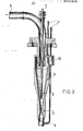
- FIG. 2 the cyclone 4 with subsequent Venturi tube 6 and delivery line 8 is shown in more detail: as can be seen, the cyclone at the lower end merges seamlessly into the Venturi tube 6, at the entrance of which the nozzle 9 of the injector 7 is arranged with the help of which the separated fine grain reaches the delivery line 8.
- the exhaust gas entering the cyclone via the inlet opening 10 passes through the system in a purified manner via 5. Finally, the operation of the arrangement can be checked via a differential pressure measurement 11.
- FIGS. 1 and 2 An laboratory-tested embodiment of the invention in the manner schematically illustrated by FIGS. 1 and 2 had the following dimensions: the cyclone with an inner diameter of 65 mm was extended at the narrowest point by a venturi tube with a diameter of 8 mm connected a conveyor tube with a diameter of 20 mm. The nozzle opening had a diameter of 1.5 mm and was arranged at a distance of 25 mm from the narrowest cross section of the Venturi tube.
- the amount of fine dust discharged from the furnace was reduced with the aid of the invention from about 5 kg / h to less than 200 g / h, although the gas velocity in the fluidized bed was increased by the propellant gas blown in, namely the total amount of exhaust gas was about 20 Nm 3 / h; the gas quantity for the driving jet was 1.2 Nm 3 / h.
- a differential pressure of 20 mbar was measured.
- the gas supply to the injector 7 is expediently passed through the furnace itself for appropriate temperature control.
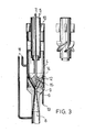
- annular gap 12 directed towards the cone wall is provided at the entrance of the discharge cone of the cyclone, which is supplied with additional gas via a connection 13.
- a guide cone 14 provided at the end of the nozzle 9 ensures a smooth entry of the dust particle into the discharge cone and its shape is adapted to the flow behavior of the cyclone in this discharge area.
- Centering pins 15 ensure an exact alignment of the nozzle 9.
- the cyclone had an inner diameter of 80 mm.
- the diameter of the narrowest point 6 of the Venturi tube was 8 mm in diameter and the nozzle 9 was 2.2 mm.
- the diameter of the immersion or delivery pipe 8 was 32 mm and that of the exhaust pipe 5 was 45 mm.
- the amount of exhaust gas totaled 4 0 Nm 3 / h. 2.2 Nm 3 / h were supplied through the propellant gas line 7.
- the annular gap had a clear width of 0.15 mm and was supplied with 1 Nm 3 / h of additional gas.
- the system according to the invention with a venturi tube at the cyclone outlet with an upstream injector nozzle 9 ensures that even poorly flowing dust is re-introduced into a fluidized bed under differential pressures of up to 1500 to 2000 mbar. Quantities range from about 5% as propellant, based on the gas throughput of the cyclone.
- the advantages of the system are the elimination of mechanically moving components as well as a cooling of the fine dust and any risk of clogging in the delivery line. Furthermore, the amount of dust to be handled outside the vortex reactor can be greatly reduced.
- the separation device according to the invention does not have to be included in the fluidized bed reactor in the manner shown, but, if necessary, must also be arranged outside the fluidized bed reactor. It may also be expedient to convey the separated grain to other process stages or, if necessary, to a bunker.
Abstract
Die Weiterbeförderung des in einem Zyklon aus dem Abgas einer Wirbelschicht abgeschiedenen Feinstaubs, d.h. insbesondere die Rezyklierung des Staubes in den unteren Bereich der Wirbelschicht, wird gemäß der Erfindung dadurch erheblich verbessert, daß in Verlängerung des Zyklons ein Venturi-Rohr sowie ein Gasinjektor am Eingang des Venturi-Rohres vorgesehen wird. Auf diese Weise lassen sich insbesondere schlecht fließende Feinstäube mit einem in den Wirbelschichtreaktor einbezogenen Zyklon effektiv aus dem Abgas abscheiden und in die Wirbelschicht zurückgeben. Das in den Injektor geführte Gas wird insbesondere zur Vorheizung durch den Wirbelschichtreaktor geleitet. Der Anteil des durch den Injektor in den Wirbelschichtreaktor gelangenden Zusatzgases kann größenordnungsmäßig bei etwa 10 % liegen. Zusätzlich kann durch einen Ringspalt am Eingang des Auslaufkonus des Zyklons ein fortwährender Gasstrom über die Konusfläche geleitet werden, der ein Anbacken von Staubpartikeln verhindert.The onward transport of the fine dust separated from the exhaust gas of a fluidized bed in a cyclone, i.e. in particular the recycling of the dust in the lower region of the fluidized bed is considerably improved according to the invention in that a venturi tube and a gas injector are provided at the entrance of the venturi tube in the extension of the cyclone. In this way, particularly poorly flowing fine dusts can be effectively separated from the exhaust gas with a cyclone incorporated in the fluidized bed reactor and returned to the fluidized bed. The gas fed into the injector is passed through the fluidized bed reactor in particular for preheating. The proportion of the additional gas entering the fluidized bed reactor through the injector can be of the order of magnitude around 10%. In addition, a continuous gas flow can be passed over the cone surface through an annular gap at the entrance of the outlet cone of the cyclone, which prevents dust particles from caking.
Description
Die Erfindung bezieht sich auf eine Vorrichtung zur Feinstaubabscheidung bei einem Wirbelschichtreaktor mit einem Zyklon mit Staubförderrohr.The invention relates to a device for fine dust separation in a fluidized bed reactor with a cyclone with a dust delivery pipe.
Bei Prozessen in der Wirbelschicht mit sich ändernder Teilchengröße, wie insbesondere bei der Wirbelschichtverbrennung, etwa von Graphit, wird mit dem Abgasstrom Feingut ausgetragen, das abgetrennt und rückgeführt oder weiterbefördert (z.B. eingebunkert) werden muß. Dabei treten Schwierigkeiten auf, wenn der Feinstaub schlechte Fließeigenschaften besitzt.In processes in the fluidized bed with changing particle size, such as in particular in the case of fluidized bed combustion, for example of graphite, fines are discharged with the exhaust gas stream, which must be separated and recycled or conveyed on (e.g., bunkered). Difficulties arise when the fine dust has poor flow properties.
So konnten bislang Abtrennung und Rückführung des Feinstaubes bei einer Graphitverbrennung in der Wirbelschicht nicht - wie seit langem bekannt - mit einem innerhalb des Ofens liegenden System aus Zyklon mit anschließendem zum unteren Bereich der Wirbelschicht reichenden Förderrohr erreicht werden. Vielmehr wurden bislang externe Abscheidungssysteme verwendet, bei denen der Staub entweder mit Hilfe einer Schieberschleuse oder eines nachgeschalteten Injektionssystems rezykliert wird.So far, it has not been possible to separate and recirculate the fine dust during graphite combustion in the fluidized bed - as has long been known - with a cyclone system inside the furnace with a subsequent delivery pipe reaching to the lower region of the fluidized bed. Rather, external separation systems have been used so far, in which the dust is recycled either with the aid of a slide gate or a downstream injection system.
Nachteile dieser Systeme sind der hohe Aufwand an mechanisch bewegten Teilen, die Abkühlung des Materials vor dem Wiedereintritt in das Wirbelbett und vor allem Fließ- und Verstopfungsprobleme im Bunker und Fördersystem.Disadvantages of these systems are the high cost of mechanically moving parts, the cooling of the material before it re-enters the fluidized bed and, above all, flow and blockage problems in the bunker and conveyor system.
Ziel der Erfindung ist es, hier Abhilfe zu schaffen mit Hilfe eines Systems, das ohne großen technischen Aufwand eine überraschend störungsfreie Feinstaubrezyklierung ermöglicht und ohne weiteres in den Wirbelschichtreaktor mit einbezogen werden kann.The aim of the invention is to remedy this with the aid of a system which enables surprisingly trouble-free recycling of fine dust without great technical effort and which can easily be incorporated into the fluidized bed reactor.
Die zu diesem Zweck entwickelte Vorrichtung der eingangs genannten Art ist gekennzeichnet durch ein-den Feststoffauslaß des Zyklons verlängerndes Venturi-Rohr zwischen Zyklon und Förderrohr und einen Gasinjektor am Eingang des Venturi-Rohres.The device of the type mentioned at the outset, which was developed for this purpose, is characterized by a venturi tube, which extends the solids outlet of the cyclone, between the cyclone and delivery tube and a gas injector at the entrance of the venturi tube.
Bei dieser Vorrichtung wird der vom Wirbelbett abgehende Feinstaub mit einem Zyklon aus dem Abgas abgeschieden, dessen Staubabzug abweichend vom sonst üblichen Konzept nicht abgeschlossen ist, sondern durch ein Venturi-Rohr verlängert wird, und in dem ferner ein Injektorsystem am Eingang des Venturi-Rohres vorhanden ist, mit dessen Hilfe das im Zyklon abgeschiedene Material in den unteren Bereich des Wirbelbetts eingeblasen werden kann.In this device, the fine dust coming from the fluidized bed is separated from the exhaust gas with a cyclone, the dust extraction of which, contrary to the usual concept, is not completed, but is extended by a venturi tube, and in which there is also an injector system at the entrance of the venturi tube with the help of which the material separated in the cyclone can be blown into the lower region of the fluidized bed.
Das Injektorsystem dient hierbei einerseits als Schleuse zwischen dem Druckniveau des Zyklons und dem Druckniveau der Förderleitung, und andererseits fördert der Treibstrahl den schlecht fließenden Feinstaub durch die als Venturi-Rohr ausgeführte Förderleitung. Dabei kann die Wirkung des Zyklons durch Ein- oder Ausschalten des Treibstrahls ein- bzw. ausgeschaltet werden.The injector system serves on the one hand as a sluice between the pressure level of the cyclone and the pressure level of the delivery line, and on the other hand the driving jet conveys the poorly flowing fine dust through the delivery line designed as a venturi tube. The effect of the cyclone can be switched on or off by switching the driving jet on or off.
Insbesondere für die Förderung bzw. den Austrag extrem schlecht fließender Staube (wie etwa Mischungen aus Uranoxid und Graphit) ist vorzugsweise ein Ringspalt am Eingang des Auslaßkonus des Zyklons vorgesehen, durch den Zusatzgas längs der Konuswand zugeführt werden kann, das einen Gasstrom längs des Konus bildet und so ein Anbacken von Staub an der Wand verhindert.Particularly for the conveyance or discharge of extremely poorly flowing dust (such as mixtures of uranium oxide and graphite), an annular gap is preferably provided at the inlet of the outlet cone of the cyclone, through which additional gas can be supplied along the cone wall, which forms a gas flow along the cone and prevents dust from sticking to the wall.
Aufbau und Arbeitsweise der erfindungsgemäßen Vorrichtung werden anhand der nachfolgend unter Bezugnahme auf die angefügten Zeichnungen beschriebenen Anwendungen in einem Wirbelschichtreaktor zur Graphitverbrennung besser verständlich werden; es zeigen:
- Figur 1 ein Schema für einen Wirbelschichtreaktor mit einbezogenem Zyklon gemäß der Erfindung;
Figur 2 den in Figur 1 ersichtlichen Zyklon in vergrößertem Maßstab undFigur 3 einen Zyklon mit Ringspalt am Auslaßkonus.
- Figure 1 is a diagram for a fluidized bed reactor with cyclone involved according to the invention;
- Figure 2 shows the cyclone shown in Figure 1 on an enlarged scale and
- Figure 3 shows a cyclone with an annular gap at the outlet cone.
Bei dem in Figur 1 gezeigten Wirbelschichtreaktor 1 mit Wirbelschicht 2, die durch ein Fluidisierungsmittel 3 im Schwebezustand gehalten wird, gelangt das abgehende Gas zusammen mit mitgeführtem Feinkorn am oberen Ende des Wirbelschichtreaktors tangential in den Zyklon 4, der für eine weitgehende Abscheidung des Kornmateriäls sorgt. Das vom Korn befreite Gas verläßt über 5 die Anlage, während das abgeschiedene Feinkorn über das Venturi-Rohr 6 angetrieben vom Injektor 7 in die Förderleitung 8 gelangt und so in die Wirbelschicht zurückkehrt.In the fluidized bed reactor 1 with fluidized
In Figur 2 ist der Zyklon 4 mit anschließendem Venturi-Rohr 6 und Förderleitung 8 mehr im einzelnen dargestellt: wie man sieht, geht der Zyklon am unteren Ende absatzlos in das Venturi-Rohr 6 über, an dessen Eingang die Düse 9 des Injektors 7 angeordnet ist, mit deren Hilfe das abgeschiedene Feinkorn in die Förderleitung 8 gelangt. Das über die Eintrittsöffnung 10 in den Zyklon gelangende Abgas gelangt gereinigt über 5 aus der Anlage. Über eine Differenzdruckmessung 11 kann schließlich die Arbeitsweise der Anordnung kontrolliert werden.In Figure 2 the
Eine im Labormaßstab erprobte Ausführungsform der Erfindung in der durch Figur 1 und 2 schematisch veranschaulichten Art hatte folgende Abmessungen: der Zyklon mit einem Innendurchmesser von 65 mm wurde durch ein Venturi-Rohr mit einem Durchmesser von 8 mm an der engsten Stelle verlängert, an das sich ein Förderrohr mit einem Durchmesser von 20 mm anschloß. Die Düsenöffnung hatte einen Durchmesser von 1,5 mm und war in einem Abstand von 25 mm vom engsten Querschnitt des Venturi-Rohres entfernt angeordnet.An laboratory-tested embodiment of the invention in the manner schematically illustrated by FIGS. 1 and 2 had the following dimensions: the cyclone with an inner diameter of 65 mm was extended at the narrowest point by a venturi tube with a diameter of 8 mm connected a conveyor tube with a diameter of 20 mm. The nozzle opening had a diameter of 1.5 mm and was arranged at a distance of 25 mm from the narrowest cross section of the Venturi tube.
Mit dieser Laborausführung wurde die aus dem Ofen ausgetragene Feinstaubmenge mit Hilfe der Erfindung von etwa 5 kg/h auf weniger als 200 g/h gesenkt, obwohl die Gasgeschwindigkeit im Wirbelbett durch das eingeblasene Treibgas erhöht wurde, und zwar betrug die Abgasmenge insgesamt etwa 20 Nm3/h; die Gasmenge für den Treibstrahl lag bei 1,2 Nm3/h. Bei 11 wurde ein Differenzdruck von 20 mbar gemessen.With this laboratory design, the amount of fine dust discharged from the furnace was reduced with the aid of the invention from about 5 kg / h to less than 200 g / h, although the gas velocity in the fluidized bed was increased by the propellant gas blown in, namely the total amount of exhaust gas was about 20 Nm 3 / h; the gas quantity for the driving jet was 1.2 Nm 3 / h. At 11 a differential pressure of 20 mbar was measured.
Bei Verwendung eines mehrstufigen Zyklonsystems könnte hier noch eine Verbesserung erreicht werden.If a multi-stage cyclone system is used, an improvement could still be achieved here.
Die Gaszufuhr zum Injektor 7 wird zweckmäßigerweise für eine entsprechende Temperierung durch den Ofen selbst geleitet.The gas supply to the
Beim Austrag extrem schlecht fließender Stäube aus dem Zyklon kann es zweckmäßig sein, wenn zusätzlich durch Einführung von Gas über einen entsprechenden Ringspalt dafür gesorgt wird, daß die Konusfläche am Zyklonausgang ständig von einem Gasstrom überstrichen wird, der das Anhaften von Staubpartikeln an einer solchen, eine gewisse Horizontalkomponente aufweisenden Wandfläche verhindert. Figur 3 zeigt eine solche Ringspaltanordnung am Ende eines Axialzyklons.When discharging extremely poorly flowing dusts from the cyclone, it may be expedient if, in addition, by introducing gas through an appropriate annular gap, it is ensured that the conical surface at the cyclone outlet is continuously swept by a gas stream that adheres the dust particles to such a prevents certain horizontal component wall surface. Figure 3 shows such an annular gap arrangement at the end of an axial cyclone.
Die der Anordnung gemäß Figur 2 entsprechenden Teile tragen gleiche Bezugszeichen. Zusätzlich ist jedoch ein zur Konuswand hin gerichteter Ringspalt 12 am Eingang des Austragkonus' des Zyklons vorgesehen, der über einen Anschluß 13 mit Zusatzgas versorgt wird. Ein am Ende der Düse 9 vorgesehener Leitkonus 14 sorgt für einen glatten Einlauf des Staubkorns in den Austragkonus und ist in seiner Gestalt dem Strömungsverhalten des Zyklons in diesem Austragbereich angepaßt. Zentrierstifte 15 sorgen für eine exakte Ausrichtung der Düse 9.The parts corresponding to the arrangement according to FIG. 2 have the same reference symbols. In addition, however, an
Bei der gezeigten Anordnung hatte der Zyklon einen Innendurchmesser von 80 mm. Der Durchmesser der engsten Stelle 6 des Venturi-Rohres hatte einen Durchmesser von 8 mm und die Düse 9 einen solchen von 2,2 mm. Der Durchmessesr des Tauch- bzw. Förderrohres 8 lag bei 32 mm und derjenige der Abgasleitung 5 bei 45 mm. Die Abgasmenge betrug insgesamt 40 Nm3/h. Durch die Treibgasleitung 7 wurden 2,2 Nm3/h zugeführt. Der Ringspalt hatte eine lichte Weite von 0,15 mm und wurde mit 1 Nm3/h Zusatzgas versorgt.In the arrangement shown, the cyclone had an inner diameter of 80 mm. The diameter of the
Durch das erfindungsgemäße System mit Venturi-Rohr am Zyklonausgang mit vorgeschalteter Injektordüse 9 wird ein Wiedereintrag auch schlecht fließenden Staubes in eine Wirbelschicht unter Differenzdrucken von bis zu 1500 bis 2000 mbar erreicht. Als Treibgas reichen Mengen ab etwa.5 %, bezogen auf den Gasdurchsatz des Zyklons.The system according to the invention with a venturi tube at the cyclone outlet with an
Durch den Ringspalt werden zusätzlich Gasmengen ab etwa 2,5 %, bezogen auf den Gasdurchsatz des Zyklons, zugeführt.Through the annular gap, additional gas quantities of approximately 2.5% or more, based on the gas throughput of the cyclone, are supplied.
Als Vorteile des Systems ergibt sich der Fortfall mechanisch bewegter Bauteile sowie eine Abkühlung des Feinstaubes und jeder Verstopfungsgefahr in der Förderleitung. Ferner kann die außerhalb des Wirbelreaktors zu handhabende Staubmenge stark vermindert werden.The advantages of the system are the elimination of mechanically moving components as well as a cooling of the fine dust and any risk of clogging in the delivery line. Furthermore, the amount of dust to be handled outside the vortex reactor can be greatly reduced.
Selbstverständlich muß die erfindungsgemäße Abscheidungsvorrichtung nicht in den Wirbelschichtreaktor in der gezeigten Art mit einbezogen, sondern bei Bedarf auch außerhalb des Wirbelschichtreaktors angeordnet werden. Ferner kann auch die Förderung des abgeschiedenen Korn zu anderen Verfahrensstufen oder gegebenenfalls in einen Bunker zweckmäßig sein.Of course, the separation device according to the invention does not have to be included in the fluidized bed reactor in the manner shown, but, if necessary, must also be arranged outside the fluidized bed reactor. It may also be expedient to convey the separated grain to other process stages or, if necessary, to a bunker.
Claims (6)
Applications Claiming Priority (2)
| Application Number | Priority Date | Filing Date | Title |
|---|---|---|---|
| DE3244769 | 1982-12-03 | ||
| DE19823244769 DE3244769A1 (en) | 1982-12-03 | 1982-12-03 | DEVICE FOR FINE DUST SEPARATION IN A FLUIDIZED LAYER REACTOR |
Publications (3)
| Publication Number | Publication Date |
|---|---|
| EP0111275A2 true EP0111275A2 (en) | 1984-06-20 |
| EP0111275A3 EP0111275A3 (en) | 1986-08-20 |
| EP0111275B1 EP0111275B1 (en) | 1989-07-05 |
Family
ID=6179728
Family Applications (1)
| Application Number | Title | Priority Date | Filing Date |
|---|---|---|---|
| EP83112143A Expired EP0111275B1 (en) | 1982-12-03 | 1983-12-02 | Device for separating fine powder at a fluidzed-bed reactor |
Country Status (5)
| Country | Link |
|---|---|
| US (1) | US4725409A (en) |
| EP (1) | EP0111275B1 (en) |
| JP (1) | JPS59150562A (en) |
| DE (2) | DE3244769A1 (en) |
| ZA (1) | ZA838979B (en) |
Cited By (6)
| Publication number | Priority date | Publication date | Assignee | Title |
|---|---|---|---|---|
| GB2180465A (en) * | 1985-09-18 | 1987-04-01 | British Gas Corp | Gas solid phase reactions & apparatus therefor |
| GB2180464A (en) * | 1985-09-18 | 1987-04-01 | British Gas Corp | Gas-solid phase reactions and apparatus therefor |
| EP0376912A2 (en) * | 1988-12-29 | 1990-07-04 | Monsanto Company | Fluid bed processes |
| DE3922764A1 (en) * | 1989-07-11 | 1991-01-17 | Babcock Werke Ag | METHOD AND DEVICE FOR SEPARATING SOLID FROM A GAS |
| EP0416238A1 (en) * | 1989-09-02 | 1991-03-13 | Balcke-Dürr AG | Fluidized bed reactor and method of operating same |
| EP1397521A2 (en) * | 2001-06-19 | 2004-03-17 | Voest-Alpine Industrieanlagenbau GmbH & Co. | Method and device for treating particulate material |
Families Citing this family (15)
| Publication number | Priority date | Publication date | Assignee | Title |
|---|---|---|---|---|
| US4968325A (en) * | 1987-08-24 | 1990-11-06 | Centre Quebecois De Valorisation De La Biomasse | Fluidized bed gasifier |
| US4940007A (en) * | 1988-08-16 | 1990-07-10 | A. Ahlstrom Corporation | Fast fluidized bed reactor |
| US5079379A (en) * | 1988-12-29 | 1992-01-07 | Monsanto Company | Fluid bed process |
| FI91971C (en) * | 1992-04-10 | 1994-09-12 | Borealis Holding As | Fluidized bed reactor |
| US5529591A (en) * | 1994-12-21 | 1996-06-25 | Shell Oil Company | Reverse flow separator |
| US5612003A (en) * | 1995-10-18 | 1997-03-18 | Fisher-Klosterman, Inc. | Fluidized bed wtih cyclone |
| DE19841586A1 (en) * | 1998-09-11 | 2000-03-16 | Metallgesellschaft Ag | Stationary bed fuel gasification reactor, for gasification of coal, comprises centrifugal separator for solids removal from the product gas |
| AT410802B (en) * | 2001-11-09 | 2003-08-25 | Voest Alpine Ind Anlagen | METHOD AND DEVICE FOR TREATING A FINE PARTICLE-SHAPED, IN PARTICULAR METAL-CONTAINING, INSERT MATERIAL |
| US7718139B2 (en) * | 2006-07-20 | 2010-05-18 | Westlake Longview Corporation | Process and apparatus for olefin polymerization in a fluidized bed reactor |
| US20100162625A1 (en) * | 2008-12-31 | 2010-07-01 | Innovative Energy Global Limited | Biomass fast pyrolysis system utilizing non-circulating riser reactor |
| EP2348056A1 (en) | 2010-01-26 | 2011-07-27 | Ineos Europe Limited | Process for the gas phase polymerisation of olefins |
| US8198384B1 (en) | 2011-01-10 | 2012-06-12 | Westlake Longview Corporation | Method for preventing or reducing clogging of a fines ejector |
| ITBS20130143A1 (en) * | 2013-10-11 | 2015-04-12 | Turboden Srl | OIL SEPARATOR FROM A WORK FLUID FOR ORC PLANT |
| US10035964B2 (en) * | 2014-07-04 | 2018-07-31 | Tubitak | Circulating fluidized bed gasification or combustion system |
| RU169536U1 (en) * | 2016-08-08 | 2017-03-22 | Федеральное государственное бюджетное образовательное учреждение высшего образования "Казанский национальный исследовательский технический университет им. А.Н. Туполева-КАИ" | CENTRIFUGAL THIN LAYER SEPARATOR |
Citations (12)
| Publication number | Priority date | Publication date | Assignee | Title |
|---|---|---|---|---|
| GB700511A (en) * | 1950-12-22 | 1953-12-02 | Ici Ltd | Improvements in and relating to the separation of particles entrained in a gas or vapour |
| GB769750A (en) * | 1954-05-27 | 1957-03-13 | Exxon Research Engineering Co | Apparatus for the burning and heating of finely-divided carbon-containing particles |
| FR68617E (en) * | 1952-09-24 | 1958-05-05 | Method and apparatus for treating pulp suspensions and other fluids to remove unwanted gases and particles therefrom | |
| DE973927C (en) * | 1954-02-25 | 1960-07-21 | Sulzer Ag | Cyclone air classifier for pneumatically conveyed dust-like material |
| FR1292307A (en) * | 1961-03-21 | 1962-05-04 | Perfected Cyclone | |
| US3139726A (en) * | 1959-06-01 | 1964-07-07 | Shell Oil Co | Combustion with fluidization and after-burning |
| FR1529336A (en) * | 1966-07-21 | 1968-06-14 | Standard Oil Co | Method and apparatus for preventing accumulation and agglomeration of catalyst in a fluidized solid catalyst reactor |
| DE1442501A1 (en) * | 1963-02-14 | 1968-12-19 | Voith Gmbh J M | Process for separating foreign bodies from a fluid medium by means of a cyclone and a cyclone for carrying out the process |
| GB1291343A (en) * | 1970-04-24 | 1972-10-04 | Coal Industry Patents Ltd | Particulate solid fuel combustion systems |
| FR2403378A1 (en) * | 1977-09-20 | 1979-04-13 | Projektierung Chem Verfahrenst | METHOD AND DEVICE FOR THE PRODUCTION OF GAS FROM SOLID FUELS |
| US4251484A (en) * | 1979-10-30 | 1981-02-17 | Mobil Oil Corporation | Method and apparatus for converting alcohols to hydrocarbons |
| US4279622A (en) * | 1979-07-13 | 1981-07-21 | Texaco Inc. | Gas-gas quench cooling and solids separation process |
Family Cites Families (24)
| Publication number | Priority date | Publication date | Assignee | Title |
|---|---|---|---|---|
| DD66243A (en) * | ||||
| US1463416A (en) * | 1917-11-12 | 1923-07-31 | Stromberg Motor Devices Co | Air cleaning and heating attachment for internal-combustion engines |
| US1496908A (en) * | 1921-09-09 | 1924-06-10 | Assigkno r | |
| US2414641A (en) * | 1945-06-09 | 1947-01-21 | Arnold Dryer Co | Collector |
| NL75972C (en) * | 1950-10-13 | 1900-01-01 | ||
| US2759511A (en) * | 1952-02-07 | 1956-08-21 | Jacobson Sven | Apparatus for hulling grain |
| US2848381A (en) * | 1953-12-16 | 1958-08-19 | Exxon Research Engineering Co | Gas-solids separation in high temperature coking |
| US2958420A (en) * | 1957-05-27 | 1960-11-01 | Phillips Petroleum Co | Hydrocyclone and process |
| US3136705A (en) * | 1959-01-09 | 1964-06-09 | Metallgesellschaft Ag | Method and apparatus for carrying out physical and chemical processes between finelydivided solids and gases in a fluidized bed |
| US3034647A (en) * | 1959-06-25 | 1962-05-15 | Ametek Inc | Cyclone separator |
| CH385605A (en) * | 1960-08-03 | 1964-12-15 | Leuna Werke Veb | Device on cyclones for the continuous discharge of separated solids |
| FR1377356A (en) * | 1963-08-12 | 1964-11-06 | Neyrpic Ateliers Neyret Beylie | Separator device |
| US3546891A (en) * | 1969-07-18 | 1970-12-15 | Lancelot A Fekete | Vortex tube process and apparatus |
| SE346705B (en) * | 1970-04-01 | 1972-07-17 | N Wikdahl | |
| US3764005A (en) * | 1971-02-22 | 1973-10-09 | Boise Cascade Corp | Hydrocyclone pulp cleaner |
| DE2124776A1 (en) * | 1971-05-19 | 1972-12-07 | Metallgesellschaft Ag | |
| SE364756B (en) * | 1972-07-07 | 1974-03-04 | Stal Laval Turbin Ab | |
| US3893914A (en) * | 1973-04-05 | 1975-07-08 | Roy A Bobo | Cyclone centrifuge apparatus |
| US4092130A (en) * | 1976-02-04 | 1978-05-30 | Wikdahl Nils Anders Lennart | Process for the separation of gas mixtures into component fractions according to their molecular or atomic weight |
| GB1561237A (en) * | 1976-09-22 | 1980-02-13 | Ahlstroem Oy | Method of treating materials in a fluidized bed reactor |
| US4235828A (en) * | 1979-06-20 | 1980-11-25 | Howes Leslie D | Fuel economizer employing improved turbulent mixing of fuel and air |
| US4259911A (en) * | 1979-06-21 | 1981-04-07 | Combustion Engineering, Inc. | Fluidized bed boiler feed system |
| US4394349A (en) * | 1981-07-06 | 1983-07-19 | Standard Oil Company (Indiana) | Apparatus for the fluidized catalytic cracking of hydrocarbon feedstock |
| US4474119A (en) * | 1982-12-27 | 1984-10-02 | Combustion Engineering, Inc. | Fine particulate feed system for fluidized bed furnace |
-
1982
- 1982-12-03 DE DE19823244769 patent/DE3244769A1/en active Granted
-
1983
- 1983-12-02 JP JP58227081A patent/JPS59150562A/en active Pending
- 1983-12-02 EP EP83112143A patent/EP0111275B1/en not_active Expired
- 1983-12-02 ZA ZA838979A patent/ZA838979B/en unknown
- 1983-12-02 DE DE8383112143T patent/DE3380143D1/en not_active Expired
-
1985
- 1985-10-21 US US06/788,696 patent/US4725409A/en not_active Expired - Fee Related
Patent Citations (13)
| Publication number | Priority date | Publication date | Assignee | Title |
|---|---|---|---|---|
| GB700511A (en) * | 1950-12-22 | 1953-12-02 | Ici Ltd | Improvements in and relating to the separation of particles entrained in a gas or vapour |
| FR1046485A (en) * | 1950-12-22 | 1953-12-07 | Ici Ltd | Recovery of particles entrained by gases or vapors |
| FR68617E (en) * | 1952-09-24 | 1958-05-05 | Method and apparatus for treating pulp suspensions and other fluids to remove unwanted gases and particles therefrom | |
| DE973927C (en) * | 1954-02-25 | 1960-07-21 | Sulzer Ag | Cyclone air classifier for pneumatically conveyed dust-like material |
| GB769750A (en) * | 1954-05-27 | 1957-03-13 | Exxon Research Engineering Co | Apparatus for the burning and heating of finely-divided carbon-containing particles |
| US3139726A (en) * | 1959-06-01 | 1964-07-07 | Shell Oil Co | Combustion with fluidization and after-burning |
| FR1292307A (en) * | 1961-03-21 | 1962-05-04 | Perfected Cyclone | |
| DE1442501A1 (en) * | 1963-02-14 | 1968-12-19 | Voith Gmbh J M | Process for separating foreign bodies from a fluid medium by means of a cyclone and a cyclone for carrying out the process |
| FR1529336A (en) * | 1966-07-21 | 1968-06-14 | Standard Oil Co | Method and apparatus for preventing accumulation and agglomeration of catalyst in a fluidized solid catalyst reactor |
| GB1291343A (en) * | 1970-04-24 | 1972-10-04 | Coal Industry Patents Ltd | Particulate solid fuel combustion systems |
| FR2403378A1 (en) * | 1977-09-20 | 1979-04-13 | Projektierung Chem Verfahrenst | METHOD AND DEVICE FOR THE PRODUCTION OF GAS FROM SOLID FUELS |
| US4279622A (en) * | 1979-07-13 | 1981-07-21 | Texaco Inc. | Gas-gas quench cooling and solids separation process |
| US4251484A (en) * | 1979-10-30 | 1981-02-17 | Mobil Oil Corporation | Method and apparatus for converting alcohols to hydrocarbons |
Non-Patent Citations (2)
| Title |
|---|
| CHEMICAL ABSTRACTS, Band 93, Nr. 6, August 1980, Seite 143, Zusammenfassung Nr. 49152k, Columbus, Ohio, US; & PL - A - 104 586 (ZAKLADY AZOTOWE "KEDZIERZYN") 31.01.1980 * |
| J.H.Perry "Chemical Engineer's Handbook", 4.Aufl., McGraw-Hill 1963, 20-48 * |
Cited By (7)
| Publication number | Priority date | Publication date | Assignee | Title |
|---|---|---|---|---|
| GB2180465A (en) * | 1985-09-18 | 1987-04-01 | British Gas Corp | Gas solid phase reactions & apparatus therefor |
| GB2180464A (en) * | 1985-09-18 | 1987-04-01 | British Gas Corp | Gas-solid phase reactions and apparatus therefor |
| EP0376912A2 (en) * | 1988-12-29 | 1990-07-04 | Monsanto Company | Fluid bed processes |
| EP0376912A3 (en) * | 1988-12-29 | 1990-09-19 | Monsanto Company | Fluid bed processes |
| DE3922764A1 (en) * | 1989-07-11 | 1991-01-17 | Babcock Werke Ag | METHOD AND DEVICE FOR SEPARATING SOLID FROM A GAS |
| EP0416238A1 (en) * | 1989-09-02 | 1991-03-13 | Balcke-Dürr AG | Fluidized bed reactor and method of operating same |
| EP1397521A2 (en) * | 2001-06-19 | 2004-03-17 | Voest-Alpine Industrieanlagenbau GmbH & Co. | Method and device for treating particulate material |
Also Published As
| Publication number | Publication date |
|---|---|
| DE3244769C2 (en) | 1987-03-05 |
| DE3244769A1 (en) | 1984-06-07 |
| DE3380143D1 (en) | 1989-08-10 |
| EP0111275A3 (en) | 1986-08-20 |
| US4725409A (en) | 1988-02-16 |
| JPS59150562A (en) | 1984-08-28 |
| ZA838979B (en) | 1984-08-29 |
| EP0111275B1 (en) | 1989-07-05 |
Similar Documents
| Publication | Publication Date | Title |
|---|---|---|
| EP0111275B1 (en) | Device for separating fine powder at a fluidzed-bed reactor | |
| EP2456561B1 (en) | Cyclone with a conduit for clean gas | |
| DE2546920C3 (en) | Electrostatic powder coating system | |
| DE2500601C2 (en) | System for the controllable discharge and compression of particulate material from a fluidized bed reactor | |
| DE1274560B (en) | Device for dedusting industrial gases | |
| DE3901859C2 (en) | Stabilized swirl flow | |
| DE3320719C2 (en) | ||
| DE2934589C2 (en) | Cyclone separator | |
| DE2401735C2 (en) | Apparatus for classifying solid particles dispersed in a carrier fluid | |
| DE19957993B4 (en) | Cone sifter and method for sifting restricted or non-pourable bulk material and support strut | |
| AT402904B (en) | OBJECT AND SYSTEM FOR SORTING BULK MATERIAL | |
| DE2932046A1 (en) | PNEUMATIC TRANSPORT DEVICE | |
| DE2819726A1 (en) | Gravity blender for powdered and particulate materials - having vessel with draw off from various locations down into pot underneath with pneumatic conveying up centre of vessel | |
| DD283834A5 (en) | DEVICE FOR GASIFICATION OF FINE-CORNIC TO DUST-FUEL FUELS | |
| EP0193976A1 (en) | Apparatus for the pyrometallurgical treatment of fine-granular solid materials to obtain fused products | |
| EP1105544B1 (en) | Method for producing zinc using the is process in an is shaft furnace | |
| DE2742099A1 (en) | DEVICE FOR HEAT TREATMENT OF FINE-GRAIN SOLIDS | |
| CH637845A5 (en) | METHOD AND DEVICE FOR INTERMITTENT, REGENERATIVE CLEANING OF A FILTER BED. | |
| DE3244742A1 (en) | Device for the discharge of solid particles from a vessel, in particular a fluidised-bed reactor, and process for operating such a device | |
| EP0563556B1 (en) | Device for mixing of fine-grained materials and/or liquids | |
| DE19507425C1 (en) | Device for increasing flow energy of solid particles such as coal dust, grain etc. by air current | |
| DD154599A1 (en) | DUESE FOR THE REGISTRATION OF DUST-SOUND GOOD IN A HORIZONTAL FOEDER LINE OF SUCTION AIR FILLING PLANTS | |
| DD154599B1 (en) | Nozzle for introducing dusty material into a horizontal conveying line of suction air conveying systems | |
| DD203237A1 (en) | DEVICE AND METHOD FOR PURIFYING DEBITORS, IN PARTICULAR GRANULES OF SYNTHETIC HIGH POLYMERS | |
| WO1982003844A1 (en) | Pneumatic powder supply installation |
Legal Events
| Date | Code | Title | Description |
|---|---|---|---|
| PUAI | Public reference made under article 153(3) epc to a published international application that has entered the european phase |
Free format text: ORIGINAL CODE: 0009012 |
|
| AK | Designated contracting states |
Designated state(s): BE CH DE FR GB LI |
|
| PUAL | Search report despatched |
Free format text: ORIGINAL CODE: 0009013 |
|
| AK | Designated contracting states |
Kind code of ref document: A3 Designated state(s): BE CH DE FR GB LI |
|
| 17P | Request for examination filed |
Effective date: 19861231 |
|
| 17Q | First examination report despatched |
Effective date: 19880211 |
|
| GRAA | (expected) grant |
Free format text: ORIGINAL CODE: 0009210 |
|
| AK | Designated contracting states |
Kind code of ref document: B1 Designated state(s): BE CH DE FR GB LI |
|
| REF | Corresponds to: |
Ref document number: 3380143 Country of ref document: DE Date of ref document: 19890810 |
|
| GBT | Gb: translation of ep patent filed (gb section 77(6)(a)/1977) | ||
| ET | Fr: translation filed | ||
| RAP4 | Party data changed (patent owner data changed or rights of a patent transferred) |
Owner name: FORSCHUNGSZENTRUM JUELICH GMBH |
|
| PLBI | Opposition filed |
Free format text: ORIGINAL CODE: 0009260 |
|
| 26 | Opposition filed |
Opponent name: EVT ENERGIE UND VERFAHRENSTECHNIK GMBH Effective date: 19900327 |
|
| PLBN | Opposition rejected |
Free format text: ORIGINAL CODE: 0009273 |
|
| STAA | Information on the status of an ep patent application or granted ep patent |
Free format text: STATUS: OPPOSITION REJECTED |
|
| 27O | Opposition rejected |
Effective date: 19910502 |
|
| PGFP | Annual fee paid to national office [announced via postgrant information from national office to epo] |
Ref country code: GB Payment date: 19941114 Year of fee payment: 12 |
|
| PGFP | Annual fee paid to national office [announced via postgrant information from national office to epo] |
Ref country code: FR Payment date: 19941215 Year of fee payment: 12 |
|
| PGFP | Annual fee paid to national office [announced via postgrant information from national office to epo] |
Ref country code: DE Payment date: 19941223 Year of fee payment: 12 |
|
| PGFP | Annual fee paid to national office [announced via postgrant information from national office to epo] |
Ref country code: BE Payment date: 19950104 Year of fee payment: 12 |
|
| PGFP | Annual fee paid to national office [announced via postgrant information from national office to epo] |
Ref country code: CH Payment date: 19950118 Year of fee payment: 12 |
|
| PG25 | Lapsed in a contracting state [announced via postgrant information from national office to epo] |
Ref country code: GB Effective date: 19951202 |
|
| PG25 | Lapsed in a contracting state [announced via postgrant information from national office to epo] |
Ref country code: LI Effective date: 19951231 Ref country code: CH Effective date: 19951231 Ref country code: BE Effective date: 19951231 |
|
| BERE | Be: lapsed |
Owner name: KERNFORSCHUNGSANLAGE JULICH G.M.B.H. Effective date: 19951231 |
|
| GBPC | Gb: european patent ceased through non-payment of renewal fee |
Effective date: 19951202 |
|
| REG | Reference to a national code |
Ref country code: CH Ref legal event code: PL |
|
| PG25 | Lapsed in a contracting state [announced via postgrant information from national office to epo] |
Ref country code: FR Effective date: 19960830 |
|
| PG25 | Lapsed in a contracting state [announced via postgrant information from national office to epo] |
Ref country code: DE Effective date: 19960903 |
|
| REG | Reference to a national code |
Ref country code: FR Ref legal event code: ST |