EP0077132A1 - Improvements in and relating to a torsion link - Google Patents
Improvements in and relating to a torsion link Download PDFInfo
- Publication number
- EP0077132A1 EP0077132A1 EP82304865A EP82304865A EP0077132A1 EP 0077132 A1 EP0077132 A1 EP 0077132A1 EP 82304865 A EP82304865 A EP 82304865A EP 82304865 A EP82304865 A EP 82304865A EP 0077132 A1 EP0077132 A1 EP 0077132A1
- Authority
- EP
- European Patent Office
- Prior art keywords
- open section
- element according
- members
- open
- section member
- Prior art date
- Legal status (The legal status is an assumption and is not a legal conclusion. Google has not performed a legal analysis and makes no representation as to the accuracy of the status listed.)
- Granted
Links
Images


Classifications
-
- B—PERFORMING OPERATIONS; TRANSPORTING
- B60—VEHICLES IN GENERAL
- B60G—VEHICLE SUSPENSION ARRANGEMENTS
- B60G11/00—Resilient suspensions characterised by arrangement, location or kind of springs
- B60G11/18—Resilient suspensions characterised by arrangement, location or kind of springs having torsion-bar springs only
-
- B—PERFORMING OPERATIONS; TRANSPORTING
- B64—AIRCRAFT; AVIATION; COSMONAUTICS
- B64C—AEROPLANES; HELICOPTERS
- B64C27/00—Rotorcraft; Rotors peculiar thereto
- B64C27/32—Rotors
- B64C27/35—Rotors having elastomeric joints
-
- F—MECHANICAL ENGINEERING; LIGHTING; HEATING; WEAPONS; BLASTING
- F16—ENGINEERING ELEMENTS AND UNITS; GENERAL MEASURES FOR PRODUCING AND MAINTAINING EFFECTIVE FUNCTIONING OF MACHINES OR INSTALLATIONS; THERMAL INSULATION IN GENERAL
- F16D—COUPLINGS FOR TRANSMITTING ROTATION; CLUTCHES; BRAKES
- F16D3/00—Yielding couplings, i.e. with means permitting movement between the connected parts during the drive
- F16D3/50—Yielding couplings, i.e. with means permitting movement between the connected parts during the drive with the coupling parts connected by one or more intermediate members
- F16D3/72—Yielding couplings, i.e. with means permitting movement between the connected parts during the drive with the coupling parts connected by one or more intermediate members with axially-spaced attachments to the coupling parts
-
- F—MECHANICAL ENGINEERING; LIGHTING; HEATING; WEAPONS; BLASTING
- F16—ENGINEERING ELEMENTS AND UNITS; GENERAL MEASURES FOR PRODUCING AND MAINTAINING EFFECTIVE FUNCTIONING OF MACHINES OR INSTALLATIONS; THERMAL INSULATION IN GENERAL
- F16F—SPRINGS; SHOCK-ABSORBERS; MEANS FOR DAMPING VIBRATION
- F16F1/00—Springs
- F16F1/02—Springs made of steel or other material having low internal friction; Wound, torsion, leaf, cup, ring or the like springs, the material of the spring not being relevant
- F16F1/14—Torsion springs consisting of bars or tubes
-
- Y—GENERAL TAGGING OF NEW TECHNOLOGICAL DEVELOPMENTS; GENERAL TAGGING OF CROSS-SECTIONAL TECHNOLOGIES SPANNING OVER SEVERAL SECTIONS OF THE IPC; TECHNICAL SUBJECTS COVERED BY FORMER USPC CROSS-REFERENCE ART COLLECTIONS [XRACs] AND DIGESTS
- Y10—TECHNICAL SUBJECTS COVERED BY FORMER USPC
- Y10T—TECHNICAL SUBJECTS COVERED BY FORMER US CLASSIFICATION
- Y10T403/00—Joints and connections
- Y10T403/45—Flexibly connected rigid members
- Y10T403/455—Elastomer interposed between radially spaced members
- Y10T403/458—Composite bushing with elastomeric component
Definitions
- This invention relates to mechanical torsion link structures and in particular to torsion links which comprise a composite of elastomeric_materials in combination with other materials such as metal.
- a structural element in accordance with the present invention is suitable for a wide variety of design applications. Furthermore the mechanical or structural element is resilient to twisting moments about one of three mutually perpendicular axes while being relatively resistant to deformations or displacements due to other forces or moments acting along or about other axes.
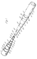
- Fig. 1 the embodiment of the elastomeric torsion link 1 of the present invention is shown with cylindrical end caps 2 and 3 shown with fasteners 4, 5 and 6 in place.
- the concentric open sections 10, 11, 12, 13, 14, 15 and 16 are shown with the outermost sections broken so as to disclose the successive adjacent inner sections and the locations respectively of the openings or slits in open sections 10, 12, 14 and 16 designated as 10', 12', 14' and 16'.
- the darker shading in the spaces between concentric open sections is elastomer 20, which is shown filling the open space and the slits 10', 12, 14' and 16'.
- the respective relative locations of the slits on the open sections 11, 13 and 15 will be more clearly shown hereinafter.
- the center of open section 16, designated as 18 is empty space.
- elastomer 20 between the open sections need not be continuous as long as its function as described hereinafter is maintained in a given application.
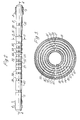
- I FI G. 2 shows a side elevational view of the complete torsion link of FIG. 1.
- concentric tubular elements 30, 31, 32, 33, 34, 25, 36, 37, 38, 39 and 40 are received on outermost open section 10 and spaced from each other so as to be independantly displaced angularly during any twisting of the link where one end is fixed or otherwise angularly displaced in an opposite direction to the angular displacement imparted to the opposite end or to a lesser or greater angular displacement in the same direction.
- the size, position and relative spacing of the tubular elements can of course be varied depending on the,particular design criteria, however, as will be more fully explained hereinafter the device shown in FIG. 2 demonstrates adherence to the principles applicable to this torsion link.
- FIG. 3 is a cross-sectional view of the torsion link of FIG. 2 with the orientation of the slits 10', 12', 14', 16', 11', 13' and 15' shown where the even numbered slits are 180° from the odd numbered slits.
- the open areas within outer tube 31 in FIG. 2 show where the elastomer 20 is located in this section.
- the outer tube 31 is also indicated. While again the elastomer torsion link of the present invention is shown in this embodiment with a specific slit orientation it is possible to pick almost any orientation as long as the function of the device is not impaired.
- FIG. 4 shows a cross-sectional view of another embodiment of the present invention where the space inside the innermost open section of the array contains a tube 60 similar to the tube 30 on the outside. As indicated previously there can be a multiplicity of these tubes spaced typically as shown or even smaller numbers than shown and even ultimately only one tube not fastened at either end to the end caps 2 or_ 3. It is preferred, also, to compliment the inside of the array at the end caps 2 and 3 with tubular members 61 and 72 for positive mechanical attachment of the fasteners 4, 5 and 6 and 7 for reasons more fully described hereinafter.
- FIGS. 5 and 6 are graphical representations of the forces which ideally will act upon the torsion link of the present invention and will be related herein to the mathematical analysis required for understanding the suitability of a particular structure for the novel design applications it is capable of undertaking.
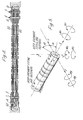
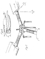
- FIGS. 7 and 8 schematically represent applications where the torsion link of the present invention can be advantageously employed.
- the torsion link of the present invention can be advantageously employed in the helicopter application shown in FIG. 7 .
- the ability of the link to withstand substantial tension as well as transverse forces or two plane bending moments at the end affixed to a rotor blade makes this application particularly attractive and would greatly simplify existing structural designs for such equipment.
- FIG. 8 several torsion links are employed at various well known points to take advantage of the unique properties of this novel structural and mechanical element with the overall result that a simple, more reliable and extremely light structure could be provided.
- the embodiments described for the new mechanical/of the present invention show broadly how open section metal tubes i.e. having a longitudinal slit, can be assembled in a concentric array to achieve the objectives of the present invention as a flexible torsion link capable of flexure, to resist bending moments,tension, compression and transverse forces. These are properties normally not associated with open sections. Functionally this is achieved in a variety of ways depending on the particular application.
- the elastomeric filling between the tubes helps resist the deformation normally associated with torsion and flexing an open section.
- further resistance to deformation can be provided with spaced sleeves encircling the torsion link which are mounted to be inde- pendant and unaffected by the twisting torques applied to the ends of the link.
- the mounts for the ends of the link are designed to prevent lateral displacement of the tube ends which structure of necessity must cooperate with the elastomer and sleeves to achieve the novel effect of this element.
- the metal selected the wall thickness of the open section, the width of the slit, the location of the slit for each adjacent concentric open section with respect to the location of the slit of the next adjacent open sections, the thickness of the space between concentric open sections to be completely or partially filled with elastomeric material, the properties of the elastomeric material itself in terms of manufacturing constraints, adhesion to the metal components, internal shear strength and the like must all be evaluated.
- the overall outside dimensions of the link, the number of concentric open sections needed and the manner of mounting must also be considered.
- Table II is a bibliography of the references whose theoretical analysis provide the foundations for the basic calculations required when approaching a given design problem utilizing the assumptions required herein.
- the critical stress G crit ' of a thin-walled section is inversely proportional to the higher power of its aspect ratio (t).
- the flexural modulus of a slit tube is proportional to the square of its aspect ratio:
- the optimum wall thickness expression is derived from a condition for minimum strain energy of a system subjected to simultaneous bending and torsion.
- the optimum wall thickness may also be determined by the expression for principal stress: in terms of the aspect ratio G p becomes:
- the best value of the wall thickness is interpolated between the ultimate principal and fatigue optima.
- Rotational displacement of one end through a given angular displacement requires a given twisting torque and together they define the torsional stiffness of the array by :
- an open section as defined herein is statically determinate, it has much lower torsional stiffness than a section with a continuous perimeter.
- Standard metals such as titanum, spring steel, aluminum alloys and the like can be employed in such an array of open sections, however, in using open sections alone, simply increasing wall thickness to prevent elastic instabilities is not feasible since the torsional stiffness is proportional to the third power of thickness.
- the onset of instabilities of an open section under stress can be expressed and solved by known differential In the elastomeric torsion link of the present invention lateral deflections is also provided by the layers of elastomeric material between the tubes of the array.
- the layers will transmit compressive stress caused by radial amplitude advance at the initial stages of buckling, from one lamination to another until it reaches the outer and inner boundary segments.
- the boundary segments will balance this compressive stress by hoop tension, or, by the tensile stress due to radial precompression.
- the most preferred embodiments of the present invention would be provided with continuous elastomeric filler between the open sections of the link, in most applications. Some applications could use less than complete filling of the interstitial space between the open section.
- transverse deflections during bending, shearing, compressive or tensile loading can be completely suppresses by interactions between the layers and boundary segments.
- the torsional stiffness of the elastomeric torsion link of the present invention is proportional to the first power of its diameter.
- Conventional elastomeric bearings exhibit torsional stiffnesses proportional to higher powers of their outer diameters.
- relatively large angular displacements in conventional bearings are difficult to obtain, but can be obtained by the use of the torsion link of the present invention without hinderance from the normally low • allowed shear strains of the materials currently available.
- This phenomenon suggests yet another embodiment of the present invention utilizing a yoke fixed to the restrained end of the present torsion .
- the elastomer filler while primarily acting as a transverse stabilizer for the open section array can also, by the judicious selection of its hardness with or without the addition of non-rubber-like- materials, be useful for dampening induced oscillations where desirable.
- Any slit tube mean radius 'r' may be expressed in terms of the number of pitches from center so where 'X' is a whole number.
- the third term may be regarded as an infinitesimal of the second order and neglected during the design stress and stress analysis.
Abstract
Description
- This invention relates to mechanical torsion link structures and in particular to torsion links which comprise a composite of elastomeric_materials in combination with other materials such as metal.
- In the past many structures have been devised which incorporate elastomeric materials in combination with various metal configurations to provide useful bearing or coupling structures for a wide variety of applications.
- Of particular interest have been the structures proposed for use in helicopter rotor root designs due to the severe requirements of such use. In particular patents such as U.S. No. 4,142,833; 3,690,639; 3,750,249; 4,037,988 and 3,787,102. The patents disclosed and discussed therein provide an excellent review of some of the efforts to provide mechanical elements to function as bearings or linkages in helicopter applications. Further structures disclosed in this art include the use of laminated metal straps, plates, rubber or rubber and metal composite belts and the like as well as filaments and filament bundles embedded in a wide variety of elastomeric materials.
- As described further in the hereinbefore identified patent literature and others, the initial experiences with elastomeric bearing designs have been somewhat disappointing. The thorough and well reasoned analysis of these early results and the extensive study of the applied forces and their resultant effect were applied almost exclusively to designs which employed metal reinforcing in the form of longitudinal or helically wound strips embedded in elastomer, or cylindrical structures-in various configurations which seemed to address the problems encountered only from the point of view of reinforcement of the elastomer.
- The prior devices utilizing as they did reinforced elastomeric materials encountered many drawbacks, some of which are detailed in the aforementioned patents. The prior reliance on the properties of the elastomer as modified by the incorporation of reinforcing materials is believed to be one of the principal reasons for the results obtained.
- It is an object of the present invention to overcome or mitigate one or more of these previously encountered problems.
- The prior problems have been eliminated by providing a plurality of differing cross-sectional sizes of open sections of metal nested or arrayed together in a manner which provides interstitial space between the sections. Elastomeric material is then incorporated into these spaces. When constructed according to this invention with retaining rings as further described hereinafter the novel mechanical element of this invention will, when properly mounted, meet all of the function requirements encountered by torsion links for an extremely wide variety of applications including helicopter rotor root assemblies.
- Advantageously a structural element in accordance with the present invention is suitable for a wide variety of design applications. Furthermore the mechanical or structural element is resilient to twisting moments about one of three mutually perpendicular axes while being relatively resistant to deformations or displacements due to other forces or moments acting along or about other axes.
- The invention will now be described, by way of example, with reference to the accompanying drawings, in which:
- Fig. 1 is a partially broken perspective view of one embodiment of the elastomeric torsion link of the present invention,
- Fig. 2 is a side elevational view of the elastomeric torsion link of Fig. 1,
- Fig. 3 is a cross-sectional view of the torsion link of Fig. 2 taken along the lines and arrows 3-3,
- Fig. 4 is a cross-sectional view of the torsion link of Fig. 2 taken along the lines and arrows 4-4,
- Fig. 5 is a pictorial perspective view graphically showing the forces and displacements that the torsion link of the present invention can encounter in use,
- Fig. 6 is a pictorial perspective view of the distribution of distortion forces in a plane tangent to the surface of a circular open section,
- Fig. 7 is a pictorial representation of the torsion link of the present invention utilized in a helicopter rotor root design embodiment,
- Fig. 8 is a pictorial representation of the torsion link of the present invention utilized in several motor car design embodiments, and
- Figs. 9 to 15 are graphs relating to characteristics of the torsion link.
- In Fig. 1, the embodiment of the
elastomeric torsion link 1 of the present invention is shown withcylindrical end caps fasteners - The concentric
open sections open sections elastomer 20, which is shown filling the open space and theslits 10', 12, 14' and 16'. The respective relative locations of the slits on theopen sections open section 16, designated as 18 is empty space. It can be filled with elastomer if necessary due to fabrication techniques or desirable for a particular application but is shown here as empty since it normally does not need to be filled. Further theelastomer 20 between the open sections need not be continuous as long as its function as described hereinafter is maintained in a given application. - I FIG. 2 shows a side elevational view of the complete torsion link of FIG. 1. Here it can be seen that concentric
tubular elements open section 10 and spaced from each other so as to be independantly displaced angularly during any twisting of the link where one end is fixed or otherwise angularly displaced in an opposite direction to the angular displacement imparted to the opposite end or to a lesser or greater angular displacement in the same direction. The size, position and relative spacing of the tubular elements can of course be varied depending on the,particular design criteria, however, as will be more fully explained hereinafter the device shown in FIG. 2 demonstrates adherence to the principles applicable to this torsion link. - FIG. 3 is a cross-sectional view of the torsion link of FIG. 2 with the orientation of the slits 10', 12', 14', 16', 11', 13' and 15' shown where the even numbered slits are 180° from the odd numbered slits. The open areas within
outer tube 31 in FIG. 2 show where theelastomer 20 is located in this section. Theouter tube 31 is also indicated. While again the elastomer torsion link of the present invention is shown in this embodiment with a specific slit orientation it is possible to pick almost any orientation as long as the function of the device is not impaired. For some applications with certain open section materials and wall thicknesses, when combined with specific elastomers, it can even be possible to have the slits of adjacent open sections aligned. Typically, it will be preferable to have some regular or random displacement of the slits of adjacent tubes so that they are not all aligned. The optimum locations will vary, however, the best locations can be obtained without undue experimentation for any given application. - FIG. 4 shows a cross-sectional view of another embodiment of the present invention where the space inside the innermost open section of the array contains a
tube 60 similar to thetube 30 on the outside. As indicated previously there can be a multiplicity of these tubes spaced typically as shown or even smaller numbers than shown and even ultimately only one tube not fastened at either end to theend caps 2 or_ 3. It is preferred, also, to compliment the inside of the array at theend caps tubular members 61 and 72 for positive mechanical attachment of thefasteners - FIGS. 5 and 6 are graphical representations of the forces which ideally will act upon the torsion link of the present invention and will be related herein to the mathematical analysis required for understanding the suitability of a particular structure for the novel design applications it is capable of undertaking.
- FIGS. 7 and 8 schematically represent applications where the torsion link of the present invention can be advantageously employed. For example, in the helicopter application shown in FIG. 7 the ability of the link to withstand substantial tension as well as transverse forces or two plane bending moments at the end affixed to a rotor blade makes this application particularly attractive and would greatly simplify existing structural designs for such equipment. Likewise, in the conceptual drawing of a motor car in FIG. 8 several torsion links are employed at various well known points to take advantage of the unique properties of this novel structural and mechanical element with the overall result that a simple, more reliable and extremely light structure could be provided.
- structure The embodiments described for the new mechanical/of the present invention show broadly how open section metal tubes i.e. having a longitudinal slit, can be assembled in a concentric array to achieve the objectives of the present invention as a flexible torsion link capable of flexure, to resist bending moments,tension, compression and transverse forces. These are properties normally not associated with open sections. Functionally this is achieved in a variety of ways depending on the particular application. For example, the elastomeric filling between the tubes helps resist the deformation normally associated with torsion and flexing an open section. Optionally further resistance to deformation can be provided with spaced sleeves encircling the torsion link which are mounted to be inde- pendant and unaffected by the twisting torques applied to the ends of the link. Further, in the embodiments shown, the mounts for the ends of the link are designed to prevent lateral displacement of the tube ends which structure of necessity must cooperate with the elastomer and sleeves to achieve the novel effect of this element.
- Many variables are present in the structure of the current device which must be considered when evaluating any particular design application. For example, the metal selected, the wall thickness of the open section, the width of the slit, the location of the slit for each adjacent concentric open section with respect to the location of the slit of the next adjacent open sections, the thickness of the space between concentric open sections to be completely or partially filled with elastomeric material, the properties of the elastomeric material itself in terms of manufacturing constraints, adhesion to the metal components, internal shear strength and the like must all be evaluated. Of course the overall outside dimensions of the link, the number of concentric open sections needed and the manner of mounting must also be considered.
- The following theoretical analysis of the interaction of all these and other variables will give guidance to a designer in establishing how a specific structure must be made to satisfy specific design criteria for any given application problem.
- The following Table I of symbols and units will be applicable to the calculations shown.


- Table II is a bibliography of the references whose theoretical analysis provide the foundations for the basic calculations required when approaching a given design problem utilizing the assumptions required herein.

- In theory, if a thin walled open section is subjected to torsion,an induced tensile - compressive stress is generated. This stress can be calculated according to the following formula,where:
- G1 is the induced axial stress (14m-2) ; G is the shear modulus of slit tubes in (Kg m-2); is the angular displacement (radians); t is the wall thickness (m); L is the length of the link or the distance between the innermost fasteners (m) and ν is Poisson's Ratio:


- This relationship shows that the induced axial stress is proportional to Saint Venant's shearing stress. Additionally even though the amplified shearing stresses are orthogonal to Gi both increase with increases in the wall thickness (t).
- However, the second component of axial stresses, generated by external bending moments, decreases with wall thickness 't', since in general, the flexural modulus is proportional to 't'.
- For example, in the case of a thin-walled slit tube


- By this condition an optimum wall thickness 'topt' follows for which Rankine's theory of failure

- The critical stress Gcrit' of a thin-walled section is inversely proportional to the higher power of its aspect ratio (t).
- However, the highest possible aspect ratios (


- Since "total strain energy" and "shear strain energy" theories of failure are more restrictive than Rankine's, the optimum wall thickness expression is derived from a condition for minimum strain energy of a system subjected to simultaneous bending and torsion.


- Taking the fatigue limit or number of cycles till failure as a criterion the second optimum thickness becomes:

- The optimum wall thickness may also be determined by the expression for principal stress:


- If (


- The best value of the wall thickness is interpolated between the ultimate principal and fatigue optima.
- Rotational displacement of one end through a given angular displacement requires a given twisting torque and together they define the torsional stiffness of the array by :

- Since an open section as defined herein is statically determinate, it has much lower torsional stiffness than a section with a continuous perimeter. Standard metals such as titanum, spring steel, aluminum alloys and the like can be employed in such an array of open sections, however, in using open sections alone, simply increasing wall thickness to prevent elastic instabilities is not feasible since the torsional stiffness is proportional to the third power of thickness. The onset of instabilities of an open section under stress can be expressed and solved by known differentialIn the elastomeric torsion link of the present invention
 lateral deflections is also provided by the layers of elastomeric material between the tubes of the array. The layers will transmit compressive stress caused by radial amplitude advance at the initial stages of buckling, from one lamination to another until it reaches the outer and inner boundary segments. The boundary segments will balance this compressive stress by hoop tension, or, by the tensile stress due to radial precompression. Clearly then, the most preferred embodiments of the present invention would be provided with continuous elastomeric filler between the open sections of the link, in most applications. Some applications could use less than complete filling of the interstitial space between the open section. In addition, transverse deflections during bending, shearing, compressive or tensile loading can be completely suppresses by interactions between the layers and boundary segments. Also, bending moments applied to attachments are transmitted through the fasteners to the thin-walled tubes as shown in the drawings. While this design is capable of deconcentrating high local stress, the end boundary segments should typically be designed to have sufficient bearing area for adequate, gradual diffusion of externally applied bending moments to the tube sides relieving the stress at the fastener.
- The torsional stiffness of the elastomeric torsion link of the present invention is proportional to the first power of its diameter. Conventional elastomeric bearings exhibit torsional stiffnesses proportional to higher powers of their outer diameters. Thus, relatively large angular displacements in conventional bearings are difficult to obtain, but can be obtained by the use of the torsion link of the present invention without hinderance from the normally low • allowed shear strains of the materials currently available. This phenomenon suggests yet another embodiment of the present invention utilizing a yoke fixed to the restrained end of the present torsion.link-and extending around the link to a predetermined position along its length where a conventional elastomeric bearing engages the yoke and a sleeve around the torsion link of the present invention.. Such a hybrid, while capable of exhibiting the greater angular displacement of the present invention could withstand a greater bending moment so the load carrying capacity utilizing the hybrid would be increased.
- Further to the foregoing the elastomer filler while primarily acting as a transverse stabilizer for the open section array can also, by the judicious selection of its hardness with or without the addition of non-rubber-like- materials, be useful for dampening induced oscillations where desirable. This of course suggests that a wide variety of available materials can be employed with particular materials being selected depending on their performance in the array for the particular design application.
- Likewise calculations for compression loading comparing an open section and the element of the present invention and test observations confirm that the elastomeric torsion link is more resistant to the onset of local instability under compressive load. Indeed the critical fatigue values for the onset of buckling or other failure modes under twisting torque; compression during shear; and tension during shear are all improved by the elastomeric torsion link of the present invention when compared theoretically with the same
- For an array it must be assumed that there are 'n' slit tubes whose section constants are analyzed. The pitch 'or' and a uniform slit tube wall thickness 'topt' are known quantities from prior calcualtions.
- Since the outer radius γom is divided into 'n' uniform pitches:

- Any slit tube mean radius 'r' may be expressed in terms of the number of pitches from center so

- Raising both sides of this relation to the power of 3:

δ 3x3


- The second and third terms within parentheses are much smaller than the first.
- If γom/δ = 10, then the third term may be regarded as an infinitesimal of the second order and neglected during the design stress and stress analysis.
- In case of the total cross-sectional area


- In the case of an array the torsional stiffness is given by:


- Total torsional stiffness, taking into account various secondary effects, by function

- When various secondary effects are compared within the "γ" function it is obvious that the "torsion-flexion" interaction is greatest. This interaction was first investigated by Timoshenko and Wagner.
- Its hyperbolic form can be reduced by Taylor's polinomial to read:

- It has been found experimentally that the torsional stiffness of the slit tube array without elastomeric interface will be increased by 15% or by the coefficient 1.15, when elastomeric material is injected:
γ ELASTOMERIC TORSION LINK = 1.15 x γ - Referring now to Figures 9 to 15 these are graphs showing various characteristics of the torsion link for varying thickness and aspect ratio (

- Figure 9 Cross-sectional area - A (m2)
- Figure 10 Flexural modulii - Z (m3)
- Figure 11 Moment of Inertia - I (m4)
- Figure 12 Outermost radii ro (m )
- Figure 13 Number of laminated slit tubes - N
- Figure 14 Weight - W (KG)
- Figure 15 Torsional stiffness - Mx
- A thorough analysis of the shear strain in the elastomeric material for any given angular displacement of concentric open sections must be made to determine the optimum spacing and govern material selection.
- The analysis must of course be undertaken for any given set of design requirements, for any application, however, it has straight forwardly been determined that the empirical results follow and exceed conventional open section evaluations to an extent that enables the use of the elastomeric torsion link of this invention in applications which hitherto would' not have been considered acceptable for open sections alone.
- Further analysis following accepted theory demonstrates that the induced by torsion tensile and compressive stresses, for example in the vicinity of the fasteners, are proportional to the shearing stress of a St. Venant's torsion.
- The foregoing analysis does of course assume devices constructed with uniform wall thickness. It is contemplated that variations in wall thickness can be employed which will require further analysis to determine suitability of specific structures for specific design applications. Likewise the elastomeric material would vary in thickness in such a situation and this would have to be taken into consideration. For some applications it would even be possible to have discontinuous elastomer filling between the open sections using longitudinal beams or webs of elastomer or even spaced annular rings and it is even further possible to use foamed elastomer or filled elastomer. The selection of the particular elastomer composition or physical shape or form will be straightforwardly achieved by workers in that art given specific design criteria for a given application and the physical data for the elastomer.
Claims (11)
Applications Claiming Priority (2)
| Application Number | Priority Date | Filing Date | Title |
|---|---|---|---|
| GB08127751A GB2105818B (en) | 1981-09-15 | 1981-09-15 | Torsion link |
| GB8127751 | 1981-09-15 |
Publications (2)
| Publication Number | Publication Date |
|---|---|
| EP0077132A1 true EP0077132A1 (en) | 1983-04-20 |
| EP0077132B1 EP0077132B1 (en) | 1986-09-10 |
Family
ID=10524501
Family Applications (1)
| Application Number | Title | Priority Date | Filing Date |
|---|---|---|---|
| EP82304865A Expired EP0077132B1 (en) | 1981-09-15 | 1982-09-15 | Improvements in and relating to a torsion link |
Country Status (6)
| Country | Link |
|---|---|
| US (1) | US4521003A (en) |
| EP (1) | EP0077132B1 (en) |
| BR (1) | BR8205381A (en) |
| CA (1) | CA1192767A (en) |
| DE (1) | DE3273202D1 (en) |
| GB (1) | GB2105818B (en) |
Cited By (3)
| Publication number | Priority date | Publication date | Assignee | Title |
|---|---|---|---|---|
| EP0125761A2 (en) * | 1983-03-18 | 1984-11-21 | Steven L. Odobasic | Laminated tubular link |
| WO1992010375A1 (en) * | 1990-12-12 | 1992-06-25 | Aragonesa De Equipamientos Para Automoviles, S.A. Adepasa | Suspension for vehicles |
| EP0549455A1 (en) * | 1991-12-26 | 1993-06-30 | AEROSPATIALE Société Nationale Industrielle | Cylindric elastomeric bearing system with large angular deflection |
Families Citing this family (5)
| Publication number | Priority date | Publication date | Assignee | Title |
|---|---|---|---|---|
| GB2105818B (en) * | 1981-09-15 | 1985-09-04 | Steven Odobasic | Torsion link |
| GB8322114D0 (en) * | 1983-08-17 | 1983-09-21 | Atomic Energy Authority Uk | Twist beam |
| GB2165333A (en) * | 1984-09-26 | 1986-04-09 | Steven Odobasic | Laminated torsion elements |
| GB2165026A (en) * | 1984-09-26 | 1986-04-03 | Jose A Avila | Composite torsion link |
| US6585445B1 (en) * | 1998-04-21 | 2003-07-01 | Vanderbilt University | Split tube flexure |
Citations (10)
| Publication number | Priority date | Publication date | Assignee | Title |
|---|---|---|---|---|
| US2151216A (en) * | 1938-04-30 | 1939-03-21 | Autogiro Co Of America | Construction of aircraft sustaining rotors |
| DE838841C (en) * | 1949-10-14 | 1952-05-15 | Leon Thiry | Elastic connection |
| FR1168281A (en) * | 1956-12-28 | 1958-12-05 | Fritz Menze | Process for the production of articulation pins with limited rotational movement |
| US2873110A (en) * | 1954-10-25 | 1959-02-10 | Jonsson Einar | Torsion spring |
| US2910843A (en) * | 1956-04-14 | 1959-11-03 | Happ Hermann | Resilient rotary connections for drive shafts |
| US3330362A (en) * | 1966-05-31 | 1967-07-11 | Lockheed Aircraft Corp | Helicopter rotor |
| US3669566A (en) * | 1969-05-20 | 1972-06-13 | Aerospatiale | Rotor construction |
| US3690639A (en) * | 1970-10-05 | 1972-09-12 | Caterpillar Tractor Co | Helically wound laminated bearings and method of manufacture |
| US3764230A (en) * | 1972-07-05 | 1973-10-09 | United Aircraft Corp | Articulated helicopter rotor utilizing plural elastomeric bearings for articulated support of the blade from the rotor hub |
| US3787102A (en) * | 1973-02-05 | 1974-01-22 | Lord Corp | Stabilized tubular compressive load carrying laminated bearing |
Family Cites Families (30)
| Publication number | Priority date | Publication date | Assignee | Title |
|---|---|---|---|---|
| US1720545A (en) * | 1927-03-05 | 1929-07-09 | Rodic Rubber Company | Resilient shackle |
| US2225966A (en) * | 1934-01-19 | 1940-12-24 | Chrysler Corp | Wheel suspension |
| US2216455A (en) * | 1938-01-27 | 1940-10-01 | Transit Res Corp | Torsion suspension |
| US2251698A (en) * | 1939-04-06 | 1941-08-05 | Corwin D Willson | Road vehicle construction |
| US2267312A (en) * | 1940-02-08 | 1941-12-23 | Budd Edward G Mfg Co | Rubber spring and method for making same |
| US2378099A (en) * | 1943-10-05 | 1945-06-12 | Transit Res Corp | Coupling |
| US2531059A (en) * | 1944-02-12 | 1950-11-21 | Goodrich Co B F | Means and method for treating rubber springs |
| US2448769A (en) * | 1945-09-07 | 1948-09-07 | James M W Chamberlain | Fluid-coupling assembly |
| US2575533A (en) * | 1947-04-16 | 1951-11-20 | Charles M Seibel | Rotor blade mounting and control |
| GB748587A (en) * | 1953-12-19 | 1956-05-02 | Austin Motor Co Ltd | Torsion bars |
| GB851377A (en) * | 1957-11-01 | 1960-10-19 | Cav Ltd | Engine starting apparatus |
| US3020036A (en) * | 1958-02-21 | 1962-02-06 | Gelenkwellenbau Gmbh | Rubber spring |
| US3052305A (en) * | 1958-03-14 | 1962-09-04 | Williams Res Corp | Pressure jet type helicopter |
| US2940785A (en) * | 1959-01-26 | 1960-06-14 | Fred L Haushalter | Bushing structure |
| US3261407A (en) * | 1964-08-05 | 1966-07-19 | Lockheed Aircraft Corp | Helicopter rotor system |
| US3342041A (en) * | 1965-10-19 | 1967-09-19 | Collins Radio Co | High stress insulated coupling |
| US3765267A (en) * | 1969-05-20 | 1973-10-16 | Aerospatiale | Connecting element between two members enabling them to rotate in relation to one another in three axes |
| DE1955308C3 (en) * | 1969-11-04 | 1978-05-24 | Raoul Dipl.-Ing. 8992 Hengnau Joern | Rubber-metal articulated bush |
| US3791234A (en) * | 1970-05-18 | 1974-02-12 | Lockheed Aircraft Corp | A retention member |
| US3797964A (en) * | 1971-06-24 | 1974-03-19 | T Hanson | Rotary wing apparatus |
| US3855817A (en) * | 1972-04-19 | 1974-12-24 | Gates Rubber Co | Flexible shaft |
| FR2214067B1 (en) * | 1973-01-12 | 1976-05-14 | Paulstra Sa | |
| JPS5246582B2 (en) * | 1973-02-09 | 1977-11-25 | ||
| US4007924A (en) * | 1975-06-27 | 1977-02-15 | Raoul Jorn | Elastic support mount |
| US4111605A (en) * | 1976-12-16 | 1978-09-05 | The Boeing Company | Composite hingeless rotor hub for rotary wing aircraft |
| FR2397327A1 (en) * | 1977-07-13 | 1979-02-09 | Aerospatiale | VARIABLE STEP ROTOR, ESPECIALLY FOR A GIRAVION |
| US4171920A (en) * | 1977-11-10 | 1979-10-23 | The B. F. Goodrich Company | Torsion spring means |
| US4349184A (en) * | 1978-04-03 | 1982-09-14 | Barry Wright Corporation | Laminated bearings having elastomer layers of varying dimensions |
| DE2917301C3 (en) * | 1979-04-28 | 1981-12-17 | Messerschmitt-Bölkow-Blohm GmbH, 8000 München | Flapping, swiveling and blade adjustment jointless rotor |
| GB2105818B (en) * | 1981-09-15 | 1985-09-04 | Steven Odobasic | Torsion link |
-
1981
- 1981-09-15 GB GB08127751A patent/GB2105818B/en not_active Expired
-
1982
- 1982-08-20 CA CA000409883A patent/CA1192767A/en not_active Expired
- 1982-08-27 US US06/412,095 patent/US4521003A/en not_active Expired - Fee Related
- 1982-09-14 BR BR8205381A patent/BR8205381A/en unknown
- 1982-09-15 EP EP82304865A patent/EP0077132B1/en not_active Expired
- 1982-09-15 DE DE8282304865T patent/DE3273202D1/en not_active Expired
Patent Citations (10)
| Publication number | Priority date | Publication date | Assignee | Title |
|---|---|---|---|---|
| US2151216A (en) * | 1938-04-30 | 1939-03-21 | Autogiro Co Of America | Construction of aircraft sustaining rotors |
| DE838841C (en) * | 1949-10-14 | 1952-05-15 | Leon Thiry | Elastic connection |
| US2873110A (en) * | 1954-10-25 | 1959-02-10 | Jonsson Einar | Torsion spring |
| US2910843A (en) * | 1956-04-14 | 1959-11-03 | Happ Hermann | Resilient rotary connections for drive shafts |
| FR1168281A (en) * | 1956-12-28 | 1958-12-05 | Fritz Menze | Process for the production of articulation pins with limited rotational movement |
| US3330362A (en) * | 1966-05-31 | 1967-07-11 | Lockheed Aircraft Corp | Helicopter rotor |
| US3669566A (en) * | 1969-05-20 | 1972-06-13 | Aerospatiale | Rotor construction |
| US3690639A (en) * | 1970-10-05 | 1972-09-12 | Caterpillar Tractor Co | Helically wound laminated bearings and method of manufacture |
| US3764230A (en) * | 1972-07-05 | 1973-10-09 | United Aircraft Corp | Articulated helicopter rotor utilizing plural elastomeric bearings for articulated support of the blade from the rotor hub |
| US3787102A (en) * | 1973-02-05 | 1974-01-22 | Lord Corp | Stabilized tubular compressive load carrying laminated bearing |
Cited By (6)
| Publication number | Priority date | Publication date | Assignee | Title |
|---|---|---|---|---|
| EP0125761A2 (en) * | 1983-03-18 | 1984-11-21 | Steven L. Odobasic | Laminated tubular link |
| EP0125761A3 (en) * | 1983-03-18 | 1986-02-26 | Steven L. Odobasic | Laminated tubular link |
| WO1992010375A1 (en) * | 1990-12-12 | 1992-06-25 | Aragonesa De Equipamientos Para Automoviles, S.A. Adepasa | Suspension for vehicles |
| EP0549455A1 (en) * | 1991-12-26 | 1993-06-30 | AEROSPATIALE Société Nationale Industrielle | Cylindric elastomeric bearing system with large angular deflection |
| FR2685675A1 (en) * | 1991-12-26 | 1993-07-02 | Aerospatiale | CYLINDRICAL ELASTOMERIC BEARING DEVICE HAVING HIGH ANGULAR DISCHARGE. |
| US5330322A (en) * | 1991-12-26 | 1994-07-19 | Aerospatiale Societe National Industrielle | Cylindrical elastomeric bearing with large angular deflection |
Also Published As
| Publication number | Publication date |
|---|---|
| BR8205381A (en) | 1983-08-23 |
| CA1192767A (en) | 1985-09-03 |
| DE3273202D1 (en) | 1986-10-16 |
| GB2105818A (en) | 1983-03-30 |
| GB2105818B (en) | 1985-09-04 |
| US4521003A (en) | 1985-06-04 |
| EP0077132B1 (en) | 1986-09-10 |
Similar Documents
| Publication | Publication Date | Title |
|---|---|---|
| DE3428820C2 (en) | Vibration isolator | |
| US4183261A (en) | Shackle | |
| US7707788B2 (en) | Buckling restrained brace for structural reinforcement and seismic energy dissipation and method of producing same | |
| US4898515A (en) | External wrap of composite flexbeam | |
| EP0077132A1 (en) | Improvements in and relating to a torsion link | |
| US20020095879A1 (en) | Low cost, light weight, energy-absorbing earthquake brace | |
| US20180363316A1 (en) | Composite sleeve rod axial dampener for buildings and structures | |
| US6500071B1 (en) | Flexible coupling | |
| IL109854A (en) | Flexbeam for a helicopter bearingless main rotor assembly | |
| EP0187265A2 (en) | Laminated compound support element | |
| US4593889A (en) | Laminated tubular link | |
| US4577736A (en) | Tubular member, especially for a safety steering column for motor vehicles | |
| GB2088793A (en) | Improvements in and relating to load transmission members | |
| US4634399A (en) | Structural component for transmitting torque | |
| WO2008124674A1 (en) | High torque density flexible composite driveshaft | |
| US4666372A (en) | Composite torsion link | |
| Yildirim | Free vibration of uniaxial composite cylindrical helical springs with circular section | |
| US5976662A (en) | Joint disc made of a fiber composite material | |
| US6318527B1 (en) | Inertial vibration isolator spring for helicopter | |
| US4194372A (en) | Flexible drive coupling | |
| EP0213816B1 (en) | Composite member wound at optimized angles | |
| EP3901484A1 (en) | Yielding couplings with wires as intermediate members | |
| US3184928A (en) | Bearing | |
| JPS5877911A (en) | Element of torsion link structure | |
| DE3432602C2 (en) |
Legal Events
| Date | Code | Title | Description |
|---|---|---|---|
| PUAI | Public reference made under article 153(3) epc to a published international application that has entered the european phase |
Free format text: ORIGINAL CODE: 0009012 |
|
| AK | Designated contracting states |
Designated state(s): DE FR IT |
|
| 17P | Request for examination filed |
Effective date: 19831003 |
|
| GRAA | (expected) grant |
Free format text: ORIGINAL CODE: 0009210 |
|
| ITF | It: translation for a ep patent filed |
Owner name: BARZANO' E ZANARDO ROMA S.P.A. |
|
| AK | Designated contracting states |
Kind code of ref document: B1 Designated state(s): DE FR IT |
|
| REF | Corresponds to: |
Ref document number: 3273202 Country of ref document: DE Date of ref document: 19861016 |
|
| ET | Fr: translation filed | ||
| PLBE | No opposition filed within time limit |
Free format text: ORIGINAL CODE: 0009261 |
|
| STAA | Information on the status of an ep patent application or granted ep patent |
Free format text: STATUS: NO OPPOSITION FILED WITHIN TIME LIMIT |
|
| 26N | No opposition filed | ||
| PGFP | Annual fee paid to national office [announced via postgrant information from national office to epo] |
Ref country code: FR Payment date: 19890914 Year of fee payment: 8 |
|
| PGFP | Annual fee paid to national office [announced via postgrant information from national office to epo] |
Ref country code: DE Payment date: 19890915 Year of fee payment: 8 |
|
| ITTA | It: last paid annual fee | ||
| PG25 | Lapsed in a contracting state [announced via postgrant information from national office to epo] |
Ref country code: FR Effective date: 19910530 |
|
| PG25 | Lapsed in a contracting state [announced via postgrant information from national office to epo] |
Ref country code: DE Effective date: 19910601 |
|
| REG | Reference to a national code |
Ref country code: FR Ref legal event code: ST |