EP0034079B1 - Method and device for stabilizing the flow of a two-phase fluid - Google Patents
Method and device for stabilizing the flow of a two-phase fluid Download PDFInfo
- Publication number
- EP0034079B1 EP0034079B1 EP81400105A EP81400105A EP0034079B1 EP 0034079 B1 EP0034079 B1 EP 0034079B1 EP 81400105 A EP81400105 A EP 81400105A EP 81400105 A EP81400105 A EP 81400105A EP 0034079 B1 EP0034079 B1 EP 0034079B1
- Authority
- EP
- European Patent Office
- Prior art keywords
- flow
- phase
- conduit
- gas
- location
- Prior art date
- Legal status (The legal status is an assumption and is not a legal conclusion. Google has not performed a legal analysis and makes no representation as to the accuracy of the status listed.)
- Expired
Links
Images
Classifications
-
- F—MECHANICAL ENGINEERING; LIGHTING; HEATING; WEAPONS; BLASTING
- F16—ENGINEERING ELEMENTS AND UNITS; GENERAL MEASURES FOR PRODUCING AND MAINTAINING EFFECTIVE FUNCTIONING OF MACHINES OR INSTALLATIONS; THERMAL INSULATION IN GENERAL
- F16L—PIPES; JOINTS OR FITTINGS FOR PIPES; SUPPORTS FOR PIPES, CABLES OR PROTECTIVE TUBING; MEANS FOR THERMAL INSULATION IN GENERAL
- F16L55/00—Devices or appurtenances for use in, or in connection with, pipes or pipe systems
-
- F—MECHANICAL ENGINEERING; LIGHTING; HEATING; WEAPONS; BLASTING
- F15—FLUID-PRESSURE ACTUATORS; HYDRAULICS OR PNEUMATICS IN GENERAL
- F15D—FLUID DYNAMICS, i.e. METHODS OR MEANS FOR INFLUENCING THE FLOW OF GASES OR LIQUIDS
- F15D1/00—Influencing flow of fluids
- F15D1/02—Influencing flow of fluids in pipes or conduits
-
- F—MECHANICAL ENGINEERING; LIGHTING; HEATING; WEAPONS; BLASTING
- F16—ENGINEERING ELEMENTS AND UNITS; GENERAL MEASURES FOR PRODUCING AND MAINTAINING EFFECTIVE FUNCTIONING OF MACHINES OR INSTALLATIONS; THERMAL INSULATION IN GENERAL
- F16L—PIPES; JOINTS OR FITTINGS FOR PIPES; SUPPORTS FOR PIPES, CABLES OR PROTECTIVE TUBING; MEANS FOR THERMAL INSULATION IN GENERAL
- F16L2101/00—Uses or applications of pigs or moles
- F16L2101/40—Separating transported fluids
Definitions
- the present invention relates to a method and a device for stabilizing the flow of a two-phase fluid and more particularly for making the mixture of gas and liquid making up this fluid more homogeneous.
- the problem to be solved is linked to two-phase flows, that is to say to the flow of a fluid of which a fraction is in the liquid state and the remaining fraction in the gaseous state.
- the pumping of two-phase fluids is ensured by conventional pumping equipment as long as the volumetric ratio of gas to liquid does not exceed a limit value close to 0.1 to 0, 2, or by specially designed equipment when the volumetric ratio is greater than this limit.
- the present invention provides a method for stabilizing the flow of a two-phase gas-liquid mixture in a pipe and thus reducing, in particular the formation of gas plugs in this flow, while at least one member is introduced into the pipe. adapted to split the two-phase flow into a plurality of separate flows and to recombine them by forming a substantially homogeneous flow downstream of said member, characterized in that this member is moved in the pipe to the location of the latter ci for which the best possible stabilization of the flow is observed, and in that it is immobilized at said location.
- the invention provides a device for stabilizing the flow of a two-phase gas-liquid mixture in a pipe and thus reducing, in particular the formation of gas plugs in this flow, this device comprising at least one member adapted to fractionate the two-phase flow in a plurality of separate flows which recombine forming a substantially homogeneous flow downstream of said organ, characterized in that said organ is removable inside the pipe and includes means allowing its immobilization at a location of the conduct chosen in advance.
- This method and this device making it possible to ensure good homogenization of the gas-liquid mixture thus preventing the formation of gas plugs and / or ensuring their disappearance when there is one in the flow of a two-phase fluid.
- Figure 1 schematically shows the principle of the invention which consists in positioning, in a conduit 1, traversed by a two-phase fluid, a member 2 adapted to make the mixture of gas and liquid more homogeneous.
- This member 2 is held in the duct 1 by immobilization means shown diagrammatically at 3.
- the member 2 is movable in the conduit 1, to be located in the most suitable place of the two-phase flow.
- the movement of the member 2 can be ensured by any known means such as an operating rod, a drive device circulating in a conduit under the action of a pressurized fluid.
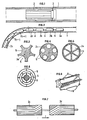
- FIG. 2 schematically shows a member 2 composed of n elements 2a, 2b, ... 2n fixed end to end by articulated connection means 4 allowing relative rotation of the successive elements with respect to each other. In this way, the member 2 can be moved in the pipe 1 even if the latter has bent portions.
- connection means may consist of ball joints, cardan joints, or any other device known to the technician. For this reason, it is not necessary to illustrate in detail the embodiments of these connection means.
- each element making up the member 2 is chosen as a function of the smallest radius of curvature of the pipe 1.
- Each element 2a, 2b, ... 2n is adapted to split the two-phase flow into a plurality of separate flows and to combine them downstream, considering the direction of flow of the fluid.
- the conduits 5 of two consecutive elements can be paired: by considering the direction of flow of the fluids represented by the arrow f, the conduits 5 of the first element are first of all axial on a first portion then helical on a second portion, while the channels of the next element are first helical then axial.
- the helical parts will have a length close to half a pitch of the propeller.
- the elements 2a, 2b, ... 2n are made of a material compatible with the flow of fluid in which they are placed. The choice of material will therefore be made by the technician among metals, reinforced or unarmed plastics, etc.
- each element in the pipe is provided in a manner known per se by centralizers such as bosses 6 carried by each element (FIG. 8).
- centralizers such as bosses 6 carried by each element (FIG. 8).
- the dimensions and the spacing between the centering bosses are determined as a function of the internal diameter and the minimum radius of curvature of the pipe to ensure easy circulation of these elements in all the portions of the pipe.
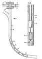
- the introduction of the device into a conduit where a pressurized fluid circulates can be carried out by means of an introductory airlock, as shown diagrammatically in FIG. 9.
- This airlock is provided with obturation blocks 8 and 9, of purge lines 10 and 11 and a pressurization line 12.
- the device 2 is fixed to the end of an operating rod 13 which is used for its establishment and its maintenance in the desired portion of the pipe 1, which is for example here a pipeline for the transport of petroleum effluents.
- the place where the device according to the invention must be positioned can be determined by taking into account changes in pumping conditions and / or pressure fluctuations upstream and downstream of the device when the position of the device is varied. this. The device is then kept in the position where these conditions are optimal, that is to say for which the flow is most stable.
- the device according to the invention is introduced upstream of the pumping member. and it is moved in the pipeline until it reaches a position for which the maximum pumping rate is obtained substantially under stable conditions. The device is then kept in this position.
- the device 2 is maintained in a production well 14 by being fixed at the end of a motor-pump unit 16 suspended from a production casing 15.
- the immobilization means can also be composed of devices marketed for example by the company OTIS and generally comprising one or more retaining sleeves preferably integrated in rectilinear portions of the pipe 1 cooperating with a latching mandrel provided with suitable retractable fingers. to enter grooves in the retaining sleeve.
- This mandrel which is integral with the device 2, makes it possible to immobilize the latter at the desired location of the pipe.
- suitable recovery means make it possible to separate the attachment mandrel from the retaining sleeve.
- organs are well known to the technician and will therefore not be described in detail.
- Such devices are, for example, described in the 1976 OTIS catalog, page 19 for the retaining sleeves designated under the name of "Landing neeple” and page 43 for the mandrel designated under the name of "Pumpdown Lock Mandrel”.
- conduits we know enough at the present time the behavior of two-phase flows in conduits to determine with a good approximation the endoits of the conduit where the instabilities of the flow will appear, according to the hydro-dynamic parameters of the flow and the geometric characteristics. conduits. In this way, during the manufacture of the conduits, it is possible to provide for the implantation of several sleeves of different internal geometries, adapted to allow the attachment only of a particular type of mandrel whose geometry is complementary to that of a sleeve so that each mandrel can only be hung on the single sleeve of the corresponding type.
- the device can be used for pipes where condensate gases circulate. Indeed, it is known that condensate accumulations such as water appear at the lowest points of the pipes increasing the risk of corrosion in these places of the pipes.
- the device according to the invention maintained in these accumulation zones promotes the dispersion in the form of a mist of the accumulated liquids and reduces the risk of corrosion.
Description
La présente invention concerne une méthode et un dispositif pour stabiliser l'écoulement d'un fluide diphasique et plus particulièrement pour rendre plus homogène le mélange de gaz et de liquide composant ce fluide.The present invention relates to a method and a device for stabilizing the flow of a two-phase fluid and more particularly for making the mixture of gas and liquid making up this fluid more homogeneous.
Des dispositifs permettant de modifier localement l'écoulement d'un liquide sont connus de l'art antérieur et par exemple décrits dans les brevets US 1 974110, 3841568 et Français 2 128 861, 2 222 560 et 2 271 492. Ces dispositifs utilisés à poste fixe dans les écoulements de liquides ont pour but de stabiliser l'écoulement, de modifier les turbulences, etc.Devices making it possible to locally modify the flow of a liquid are known from the prior art and for example described in US patents 1,974,110, 3,841,568 and French 2,128,861, 2,222,560 and 2,271,492. These devices used in fixed position in the flow of liquids is intended to stabilize the flow, modify turbulence, etc.
Le problème à résoudre est lié aux écoulements diphasiques, c'est-à-dire à l'écoulement d'un fluide dont une fraction est à l'état liquide et la fraction restante à l'état gazeux.The problem to be solved is linked to two-phase flows, that is to say to the flow of a fluid of which a fraction is in the liquid state and the remaining fraction in the gaseous state.
Ainsi, le pompage de fluides diphasiques, tels que, par exemple, des effluents pétroliers, est assuré par des matériels de pompage classiques tant que le rapport volumétrique du gaz au liquide n'excède pas une valeur limite voisine de 0,1 à 0,2, ou par des matériels conçus spécialement lorsque le rapport volumétrique est supérieur à cette limite.Thus, the pumping of two-phase fluids, such as, for example, petroleum effluents, is ensured by conventional pumping equipment as long as the volumetric ratio of gas to liquid does not exceed a limit value close to 0.1 to 0, 2, or by specially designed equipment when the volumetric ratio is greater than this limit.
Le fonctionnement de ces appareils est satisfaisant tant que le mélange gaz-liquide présente une certaine homogénéité et qu'une fraction importante de gaz ne s'accumule pas localement pour former des »bouchons de gaz« dans l'écoulement du fluide diphasique.The operation of these devices is satisfactory as long as the gas-liquid mixture has a certain homogeneity and a significant fraction of gas does not accumulate locally to form "gas plugs" in the flow of the two-phase fluid.
La présente invention propose un procédé pour stabiliser l'écoulement d'un mélange diphasique gaz-liquide dans une conduite et réduire ainsi, notamment la formation de bouchons de gaz dans cet écoulement, pendant que l'on introduit dans la conduite au moins un organe adapté à fractionner l'écoulement diphasique en une pluralité d'écoulements séparés et à les recombiner en formant un écoulement sensiblement homogène en aval dudit organe, caractérisé en ce qu'on déplace cet organe dans la conduite jusqu'à l'emplacement de celle-ci pour lequel on observe la meilleure stabilisation possible de l'écoulement, et en ce qu'on l'immobilise audit emplacement.The present invention provides a method for stabilizing the flow of a two-phase gas-liquid mixture in a pipe and thus reducing, in particular the formation of gas plugs in this flow, while at least one member is introduced into the pipe. adapted to split the two-phase flow into a plurality of separate flows and to recombine them by forming a substantially homogeneous flow downstream of said member, characterized in that this member is moved in the pipe to the location of the latter ci for which the best possible stabilization of the flow is observed, and in that it is immobilized at said location.
En outre, l'invention propose un dispositif pour stabiliser l'écoulement d'un mélange diphasique gaz-liquide dans une conduite et réduire ainsi, notamment la formation de bouchons de gaz dans cet écoulement, ce dispositif comportant au moins un organe adapté à fractionner l'écoulement diphasique en une pluralité d'écoulements séparés qui se recombinent en formant un écoulement sensiblement homogène en aval dudit organs, caractérisé en ce que ledit organe est amovible à l'intérieur de la conduite et comporte des moyens permettant son immobilisation à un emplacement de la conduite choisi à l'avance.In addition, the invention provides a device for stabilizing the flow of a two-phase gas-liquid mixture in a pipe and thus reducing, in particular the formation of gas plugs in this flow, this device comprising at least one member adapted to fractionate the two-phase flow in a plurality of separate flows which recombine forming a substantially homogeneous flow downstream of said organ, characterized in that said organ is removable inside the pipe and includes means allowing its immobilization at a location of the conduct chosen in advance.
Cette méthode et ce dispositif permettant d'assurer une bonne homogénéisation du mélange gaz-liquide empêchant ainsi la formation de bouchons de gaz et/ou assurant leur disparition lorsqu'il en éxiste dans l'écoulement d'un fluide diphasique.This method and this device making it possible to ensure good homogenization of the gas-liquid mixture thus preventing the formation of gas plugs and / or ensuring their disappearance when there is one in the flow of a two-phase fluid.
L'invention pourra être bien comprise et tous ses avantages apparaîtront à la lecture de la description qui suit illustrée par les dessins parmi lesquels:
- - la figure 1 montre schématiquement un dispositif selon l'invention,
- - la figure 2 représente plusieurs éléments composant le dispositif,
- - les figures 3 à 8 illustrent différents modes de réalisation des éléments,
- - les figures 9 et 10 montrent deux cas d'utilisation du dispositif selon l'invention.
- FIG. 1 schematically shows a device according to the invention,
- FIG. 2 represents several elements making up the device,
- - Figures 3 to 8 illustrate different embodiments of the elements,
- - Figures 9 and 10 show two cases of use of the device according to the invention.
On se réfère dans la suite, mais sans que cela soit limitatif, à un écoulement diphasique d'effluents pétroliers.Reference is made hereinafter, but without being limiting, to a two-phase flow of petroleum effluents.
La figure 1 montre schématiquement le principe de l'invention qui consiste à positionner, dans un conduit 1, parcouru par un fluide diphasique, un organe 2 adapté à rendre plus homogène le mélange de gaz et de liquide. Cet organe 2 est maintenu dans le conduit 1 par des moyens d'immobilisation schématisés en 3.Figure 1 schematically shows the principle of the invention which consists in positioning, in a
L'organe 2 est déplaçable dans le conduit 1, pour être localisé à l'endroit le mieux approprié de l'écoulement diphasique.The
Le déplacement de l'organe 2 peut être assuré par tout moyen connu tel que tige de manoeuvre, dispositif d'entraînement circulant dans un conduit sous l'action d'un fluide sous pression.The movement of the
La figure 2 montre schématiquement un organe 2 composé de n éléments 2a, 2b, ... 2n fixés bout à bout par des moyens de raccordement articulés 4 permettant une rotation relative des éléments successifs les uns par rapport aux autres. De cette façon, l'organe 2 peut être déplacé dans la conduite 1 même si celle-ci présente des portions coudées.FIG. 2 schematically shows a
Ces moyens de raccordement peuvent être constitués de rotules, de cardans à rotules, ou de tout autre dispositif connu du technicien. Pour cette raison, il n'est pas nécessaire d'illustrer en détail les modes de réalisation de ces moyens de raccordement.These connection means may consist of ball joints, cardan joints, or any other device known to the technician. For this reason, it is not necessary to illustrate in detail the embodiments of these connection means.
La longueur de chaque élément composant l'organe 2 est choisie en fonction du plus petit rayon de courbure de la conduite 1.The length of each element making up the
Chaque élément 2a, 2b, ... 2n est adapté à fractionner l'écoulement diphasique en une pluralité d'écoulements séparés et à les recombiner en aval, en considérant le sens d'écoulement du fluide.Each
Dans ce but, les éléments 2a, 2b, ... 2n sont constitués d'un barreau de forme générale cylindrique dans lequel sont ménagés des conduits 5 axiaux ou hélicoidaux. Ces conduits 5 peuvent avoir, en section droite, diverses formes dont quelques unes ont été représentées sur les figures 3 à 6:
- - section en portion de cercle, ouverte à la périphérie du
barreau 2n (fig. 3), - - section circulaire (fig. 4),
- - section triangulaire (fig. 5),
- - section en forme de secteur d'anneau (fig. 6).
- - section in a portion of a circle, open at the periphery of the
bar 2n (fig. 3), - - circular section (fig. 4),
- - triangular section (fig. 5),
- - section in the form of a ring sector (fig. 6).
Selon une variante de réalisation illustrée par la figure 7, les conduits 5 de deux éléments consécutifs peuvent être appariés: en considérant le sens d'écoulement du fluids représenté par la flèche f, les conduits 5 du premier élément sont tout d'abord axiaux sur une première portion puis hélicoidaux sur une seconde portion, tandis que les canaux de l'élément suivant sont tout d'abord hélicoidaux puis axiaux. De préférence, mais non limitativement, les parties hélicoidales auront une longueur voisine du demi pas de l'hélice.According to an alternative embodiment illustrated in FIG. 7, the
Les éléments 2a, 2b, ... 2n sont constitués en un matériau compatible avec l'écoulement de fluide dans lequel ils sont placés. Le choix du matériau sera donc effectué par le technicien parmi les métaux, les matières plastiques armées ou non armées, etc.The
Le centrage approximatif de chaque élément dans la conduite est assuré de façon connue en soi par des centreurs tels que des bossages 6 portés par chaque élément (figure 8). Comme il est bien connu des spécialistes, les dimensions et l'écartement entre les bossages centreurs sont déterminés en fonction du diamètre intérieur et du rayon de courbure minimal de la conduite pour assurer une circulation aisée de ces éléments dans toutes les portions de la conduite.The approximate centering of each element in the pipe is provided in a manner known per se by centralizers such as
L'introduction du dispositif dans un conduit où circule un fluide sous pression, peut être effectuée au moyen d'un sas 7 d'introduction, comme schématisé sur la figure 9. Ce sas est pourvu de blocs d'obturation 8 et 9, de canalisations de purge 10 et 11 et d'une canalisation de mise en pression 12.The introduction of the device into a conduit where a pressurized fluid circulates, can be carried out by means of an introductory airlock, as shown diagrammatically in FIG. 9. This airlock is provided with obturation blocks 8 and 9, of
Dans le cas illustré par la figure 9, le dispositif 2 est fixé à l'extrémité d'une tige de manoeuvre 13 qui sert à sa mise en place et à son maintien dans la portion désirée de la canalisation 1, qui est par exemple ici une canalisation pour le transport d'effluents pétroliers.In the case illustrated in Figure 9, the
L'endroit où doit être positionné le dispositif selon l'invention peut être déterminé en tenant compte des changements dans les conditions de pompage et/ou des fluctuations de pression en amont et en aval du dispositif lorsqu'on fait varier la position de celui-ci. On maintient alors le dispositif dans la position où ces conditions sont optimales, c'est-à-dire pour lesquelles l'écoulement est le plus stable.The place where the device according to the invention must be positioned can be determined by taking into account changes in pumping conditions and / or pressure fluctuations upstream and downstream of the device when the position of the device is varied. this. The device is then kept in the position where these conditions are optimal, that is to say for which the flow is most stable.
C'est ainsi par exemple que, lorsque se forment des »bouchons« ou accumulations de gaz trop importants qui réduisent notablement le débit de pompage ou empêchent même tout pompage, on introduit le dispositif selon l'invention en amont de l'organe de pompage et on le déplace dans la canalisation jusqu'à ce qu'il atteigne une position pour laquelle on obtient sensiblement le maximum du débit de pompage dans des conditions stables. On maintient alors le dispositif dans cette position.Thus, for example, when "plugs" or excessively large accumulations of gas are formed which significantly reduce the pumping rate or even prevent any pumping, the device according to the invention is introduced upstream of the pumping member. and it is moved in the pipeline until it reaches a position for which the maximum pumping rate is obtained substantially under stable conditions. The device is then kept in this position.
Dans le cas représenté par la figure 10, le dispositif 2 est maintenu dans un puits de production 14 en étant fixé à l'extrémité d'un groupe moto-pompe 16 suspendu à un tubage de production 15.In the case represented by FIG. 10, the
Les moyens d'immobilisation peuvent également être composés de dispositifs commercialisés par exemple par la société OTIS et comportant généralement un ou plusieurs manchons de retenue intégrés de préférence dans des portions rectilignes de la conduite 1 coopérant avec un mandrin d'accrochage muni de doigts escamotables adaptés à pénétrer dans des rainures du manchon de retenue. Ce mandrin, qui est solidaire du dipositif 2, permet d'immobiliser celui-ci à l'endroit désiré de la conduite. Eventuellement, des moyens de repêchage appropriés permettent de désolidariser le mandrin d'accrochage du manchon de retenue. De tels organes sont bien connus du technicien et ne seront donc pas décrits en détail.The immobilization means can also be composed of devices marketed for example by the company OTIS and generally comprising one or more retaining sleeves preferably integrated in rectilinear portions of the
De tels dispositifs sont, par exemple, décrits dans le catalogue OTIS de 1976, page 19 pour les manchon de retenue désignés sous le nom de »Landing neeple« et page 43 pour le mandrin désigné sous le nom de »Pumpdown Lock Mandrel«.Such devices are, for example, described in the 1976 OTIS catalog, page 19 for the retaining sleeves designated under the name of "Landing neeple" and page 43 for the mandrel designated under the name of "Pumpdown Lock Mandrel".
Des dispositifs semblables commercialisés par d'autres fabricants peuvent être utilisée.Similar devices sold by other manufacturers can be used.
On connaît suffisamment à l'heure actuelle le comportement des écoulements diphasiques dans les conduits pour déterminer avec une bonne approximation les endoits du conduit où apparaîtront les instabilités de l'écoulement, en fonction des paramètres hydro-dynamiques de l'écoulement et des caractéristiques géométriques des conduits. De cette façon lors de la fabrication des conduits on peut prévoir l'implantation de plusieurs manchons de géométries internes différentes, adaptés à permettre l'accrochage que d'un type particulier de mandrin dont la géométrie est complémentaire de celle d'un manchon de sorte que chaque mandrin ne peut être accroché que sur le seul manchon de type correspondant.We know enough at the present time the behavior of two-phase flows in conduits to determine with a good approximation the endoits of the conduit where the instabilities of the flow will appear, according to the hydro-dynamic parameters of the flow and the geometric characteristics. conduits. In this way, during the manufacture of the conduits, it is possible to provide for the implantation of several sleeves of different internal geometries, adapted to allow the attachment only of a particular type of mandrel whose geometry is complementary to that of a sleeve so that each mandrel can only be hung on the single sleeve of the corresponding type.
L'expérience a de plus montré que le dispositif était utilisable pour les conduites où circulent des gaz à condensats. En effet, on sait que des accumulations de condensats tels que de l'eau apparaissent aux points les plus bas des canalisations augmentant les risques de corrosion en ces endroits des canalisations. Le dispositif selon l'invention maintenu dans ces zones d'accumulation favorise la dispersion sous forme de brouillard des liquides accumulés et diminue le risque de corrosion.Experience has also shown that the device can be used for pipes where condensate gases circulate. Indeed, it is known that condensate accumulations such as water appear at the lowest points of the pipes increasing the risk of corrosion in these places of the pipes. The device according to the invention maintained in these accumulation zones promotes the dispersion in the form of a mist of the accumulated liquids and reduces the risk of corrosion.
Claims (4)
Applications Claiming Priority (2)
| Application Number | Priority Date | Filing Date | Title |
|---|---|---|---|
| FR8002054A FR2474614A1 (en) | 1980-01-30 | 1980-01-30 | METHOD AND DEVICE FOR REGULARIZING THE FLOW OF A DIPHASIC FLUID |
| FR8002054 | 1980-01-30 |
Publications (2)
| Publication Number | Publication Date |
|---|---|
| EP0034079A1 EP0034079A1 (en) | 1981-08-19 |
| EP0034079B1 true EP0034079B1 (en) | 1983-07-06 |
Family
ID=9238041
Family Applications (1)
| Application Number | Title | Priority Date | Filing Date |
|---|---|---|---|
| EP81400105A Expired EP0034079B1 (en) | 1980-01-30 | 1981-01-26 | Method and device for stabilizing the flow of a two-phase fluid |
Country Status (3)
| Country | Link |
|---|---|
| EP (1) | EP0034079B1 (en) |
| DE (1) | DE3160540D1 (en) |
| FR (1) | FR2474614A1 (en) |
Cited By (1)
| Publication number | Priority date | Publication date | Assignee | Title |
|---|---|---|---|---|
| US7303046B2 (en) | 2002-09-18 | 2007-12-04 | Savant Measurement Corporation | Apparatus for filtering ultrasonic noise within a fluid flow system |
Families Citing this family (8)
| Publication number | Priority date | Publication date | Assignee | Title |
|---|---|---|---|---|
| US4592201A (en) * | 1982-07-12 | 1986-06-03 | General Electric Company | Turbofan mixed flow exhaust system |
| FR2552173B1 (en) * | 1983-09-19 | 1987-07-24 | Inst Francais Du Petrole | DEVICE FOR STABILIZING A POLYPHASIC FLOW |
| WO1994017000A1 (en) * | 1993-01-25 | 1994-08-04 | Ion Enterprises Ltd. | Fluid treatment device and method |
| US5495872A (en) * | 1994-01-31 | 1996-03-05 | Integrity Measurement Partners | Flow conditioner for more accurate measurement of fluid flow |
| GB2341695B (en) * | 1998-09-17 | 2003-02-26 | Petroleo Brasileiro Sa | Device and method for eliminating severe slugging in multiphase-stream flow lines |
| EP3118468B1 (en) * | 2015-07-14 | 2020-08-05 | Institute of Science and Technology Austria | Re-laminarization of a turbulent flow in a duct |
| WO2019018781A1 (en) * | 2017-07-21 | 2019-01-24 | Forum Us, Inc. | Apparatus and method for regulating flow from a geological formation |
| US11008848B1 (en) | 2019-11-08 | 2021-05-18 | Forum Us, Inc. | Apparatus and methods for regulating flow from a geological formation |
Citations (4)
| Publication number | Priority date | Publication date | Assignee | Title |
|---|---|---|---|---|
| US1974110A (en) * | 1932-12-21 | 1934-09-18 | Frank R Higley | Curved conduit |
| FR2128861A1 (en) * | 1971-03-11 | 1972-10-20 | Mitsubishi Heavy Ind Ltd | |
| US3841568A (en) * | 1972-02-07 | 1974-10-15 | English Clays Lovering Pochin | Streamlined flow in fluids |
| FR2271492A1 (en) * | 1972-11-15 | 1975-12-12 | Fluid Dynamics Ltd |
Family Cites Families (1)
| Publication number | Priority date | Publication date | Assignee | Title |
|---|---|---|---|---|
| GB1469648A (en) * | 1973-03-23 | 1977-04-06 | Tokico Ltd | Liquid flow straightening device |
-
1980
- 1980-01-30 FR FR8002054A patent/FR2474614A1/en active Granted
-
1981
- 1981-01-26 EP EP81400105A patent/EP0034079B1/en not_active Expired
- 1981-01-26 DE DE8181400105T patent/DE3160540D1/en not_active Expired
Patent Citations (4)
| Publication number | Priority date | Publication date | Assignee | Title |
|---|---|---|---|---|
| US1974110A (en) * | 1932-12-21 | 1934-09-18 | Frank R Higley | Curved conduit |
| FR2128861A1 (en) * | 1971-03-11 | 1972-10-20 | Mitsubishi Heavy Ind Ltd | |
| US3841568A (en) * | 1972-02-07 | 1974-10-15 | English Clays Lovering Pochin | Streamlined flow in fluids |
| FR2271492A1 (en) * | 1972-11-15 | 1975-12-12 | Fluid Dynamics Ltd |
Cited By (3)
| Publication number | Priority date | Publication date | Assignee | Title |
|---|---|---|---|---|
| US7303046B2 (en) | 2002-09-18 | 2007-12-04 | Savant Measurement Corporation | Apparatus for filtering ultrasonic noise within a fluid flow system |
| US7303047B2 (en) | 2002-09-18 | 2007-12-04 | Savant Measurement Corporation | Apparatus for filtering ultrasonic noise within a fluid flow system |
| US7303048B2 (en) | 2002-09-18 | 2007-12-04 | Savant Measurement Corporation | Method for filtering ultrasonic noise within a fluid flow system |
Also Published As
| Publication number | Publication date |
|---|---|
| EP0034079A1 (en) | 1981-08-19 |
| FR2474614B1 (en) | 1982-01-08 |
| DE3160540D1 (en) | 1983-08-11 |
| FR2474614A1 (en) | 1981-07-31 |
Similar Documents
| Publication | Publication Date | Title |
|---|---|---|
| EP0034079B1 (en) | Method and device for stabilizing the flow of a two-phase fluid | |
| EP0330584B1 (en) | Divice for transferring fluids between the sea bottom and the surface | |
| FR2493908A1 (en) | STABILIZER FOR TUBULAR ASSEMBLY EXTENDING TO ROTATE A TREPAN INTO A SURVEY | |
| FR2848242A1 (en) | FLOW CONTROL DEVICE | |
| FR2763635A1 (en) | Downhole well element support system | |
| FR2641315A1 (en) | CONTROLLED TRACK DRILLING TRIM COMPRISING A VARIABLE GEOMETRY STABILIZER AND USE THEREOF | |
| CA2086297C (en) | Process for optimizing the control and the modulation of a multiphase flow and device thus obtained | |
| FR2505924A1 (en) | UPRIGHT PRODUCTION COLUMN ASSEMBLY CONDUCTING THE OIL TO A FLOATING PLATFORM | |
| FR2578024A1 (en) | PIVOTLESS COUPLING APPARATUS FOR COUPLING A CONDUIT FIXED TO A MOBILE SUPPORT IN THE MARINE ENVIRONMENT | |
| FR2656652A1 (en) | DEVICE FOR SEPARATING A MIXTURE OF FREE GAS AND LIQUID TO THE INTAKE OF A PUMP AT THE BOTTOM OF A WELLBORE. | |
| FR2641316A1 (en) | CONTROLLED TRACK DRILLING HAVING A VARIABLE-ANGLE ELBOW ELEMENT AND USE THEREOF | |
| FR2794842A1 (en) | UNIVERSAL SECURITY DEVICE AND METHOD FOR PROTECTING A PIPELINE | |
| WO2011064467A1 (en) | Drill string components, and string of components | |
| FR2531160A1 (en) | PERFECTLY SEMI-FLOATING BEARING | |
| FR2511740A1 (en) | APPARATUS AND METHOD FOR CONNECTING PARTICULARLY CYLINDRICAL ELEMENTS SUCH AS TUBES | |
| EP0309361A1 (en) | Fluid distributor in a pressurized container preventing thermal stratification | |
| FR2513305A1 (en) | UPLINK COLUMN EXCENTRED FOR ARTICULATED DEEP WATER OPERATION STRUCTURE | |
| EP3334898B1 (en) | Underwater facility for gas/liquid separation | |
| EP0123599A1 (en) | Dismountable fastening device for an internal structure in an envelope such as a conduit or a recipient | |
| EP0182705A1 (en) | Device for fluid transport between a fixed structure and a rotating structure using at least one flexible conduit | |
| FR2693310A1 (en) | Method of using a thermowell of a nuclear pressurized water reactor and device for adjusting the axial position of the thermowell. | |
| EP1090245A1 (en) | Method for mounting a fitting on a tube end and novel type of fitting for implementing same | |
| BE1006906A5 (en) | Milling tool and device for drilling, drilling for particular wall pipe. | |
| EP3719435B1 (en) | Insert for pipe end | |
| EP0462139B1 (en) | Through valves with rubber bushing and hemispheric closure member |
Legal Events
| Date | Code | Title | Description |
|---|---|---|---|
| PUAI | Public reference made under article 153(3) epc to a published international application that has entered the european phase |
Free format text: ORIGINAL CODE: 0009012 |
|
| AK | Designated contracting states |
Designated state(s): BE DE GB IT NL SE |
|
| 17P | Request for examination filed |
Effective date: 19811014 |
|
| ITF | It: translation for a ep patent filed |
Owner name: ST. ASSOC. MARIETTI & PIPPARELLI |
|
| GRAA | (expected) grant |
Free format text: ORIGINAL CODE: 0009210 |
|
| AK | Designated contracting states |
Designated state(s): BE DE GB IT NL SE |
|
| REF | Corresponds to: |
Ref document number: 3160540 Country of ref document: DE Date of ref document: 19830811 |
|
| PLBE | No opposition filed within time limit |
Free format text: ORIGINAL CODE: 0009261 |
|
| STAA | Information on the status of an ep patent application or granted ep patent |
Free format text: STATUS: NO OPPOSITION FILED WITHIN TIME LIMIT |
|
| 26N | No opposition filed | ||
| PGFP | Annual fee paid to national office [announced via postgrant information from national office to epo] |
Ref country code: GB Payment date: 19901213 Year of fee payment: 11 |
|
| PGFP | Annual fee paid to national office [announced via postgrant information from national office to epo] |
Ref country code: SE Payment date: 19901228 Year of fee payment: 11 |
|
| PGFP | Annual fee paid to national office [announced via postgrant information from national office to epo] |
Ref country code: BE Payment date: 19910111 Year of fee payment: 11 |
|
| ITTA | It: last paid annual fee | ||
| PGFP | Annual fee paid to national office [announced via postgrant information from national office to epo] |
Ref country code: NL Payment date: 19910131 Year of fee payment: 11 |
|
| PGFP | Annual fee paid to national office [announced via postgrant information from national office to epo] |
Ref country code: DE Payment date: 19910214 Year of fee payment: 11 |
|
| PG25 | Lapsed in a contracting state [announced via postgrant information from national office to epo] |
Ref country code: GB Effective date: 19920126 |
|
| PG25 | Lapsed in a contracting state [announced via postgrant information from national office to epo] |
Ref country code: SE Effective date: 19920127 |
|
| PG25 | Lapsed in a contracting state [announced via postgrant information from national office to epo] |
Ref country code: BE Effective date: 19920131 |
|
| BERE | Be: lapsed |
Owner name: INSTITUT FRANCAIS DU PETROLE Effective date: 19920131 |
|
| PG25 | Lapsed in a contracting state [announced via postgrant information from national office to epo] |
Ref country code: NL Effective date: 19920801 |
|
| NLV4 | Nl: lapsed or anulled due to non-payment of the annual fee | ||
| GBPC | Gb: european patent ceased through non-payment of renewal fee | ||
| PG25 | Lapsed in a contracting state [announced via postgrant information from national office to epo] |
Ref country code: DE Effective date: 19921001 |
|
| EUG | Se: european patent has lapsed |
Ref document number: 81400105.3 Effective date: 19920806 |