DE10237341A1 - Finite vortex model for use in fluid flow numerical simulation, especially for modeling unsteady flows, whereby a general roll-off model is used to model the finite edge vortex - Google Patents
Finite vortex model for use in fluid flow numerical simulation, especially for modeling unsteady flows, whereby a general roll-off model is used to model the finite edge vortex Download PDFInfo
- Publication number
- DE10237341A1 DE10237341A1 DE10237341A DE10237341A DE10237341A1 DE 10237341 A1 DE10237341 A1 DE 10237341A1 DE 10237341 A DE10237341 A DE 10237341A DE 10237341 A DE10237341 A DE 10237341A DE 10237341 A1 DE10237341 A1 DE 10237341A1
- Authority
- DE
- Germany
- Prior art keywords
- vortex
- model
- hfc
- finite
- cooling
- Prior art date
- Legal status (The legal status is an assumption and is not a legal conclusion. Google has not performed a legal analysis and makes no representation as to the accuracy of the status listed.)
- Withdrawn
Links
Classifications
-
- B—PERFORMING OPERATIONS; TRANSPORTING
- B01—PHYSICAL OR CHEMICAL PROCESSES OR APPARATUS IN GENERAL
- B01F—MIXING, e.g. DISSOLVING, EMULSIFYING OR DISPERSING
- B01F25/00—Flow mixers; Mixers for falling materials, e.g. solid particles
- B01F25/40—Static mixers
- B01F25/42—Static mixers in which the mixing is affected by moving the components jointly in changing directions, e.g. in tubes provided with baffles or obstructions
- B01F25/43—Mixing tubes, e.g. wherein the material is moved in a radial or partly reversed direction
- B01F25/431—Straight mixing tubes with baffles or obstructions that do not cause substantial pressure drop; Baffles therefor
- B01F25/4311—Straight mixing tubes with baffles or obstructions that do not cause substantial pressure drop; Baffles therefor the baffles being adjustable
-
- F—MECHANICAL ENGINEERING; LIGHTING; HEATING; WEAPONS; BLASTING
- F15—FLUID-PRESSURE ACTUATORS; HYDRAULICS OR PNEUMATICS IN GENERAL
- F15D—FLUID DYNAMICS, i.e. METHODS OR MEANS FOR INFLUENCING THE FLOW OF GASES OR LIQUIDS
- F15D1/00—Influencing flow of fluids
- F15D1/10—Influencing flow of fluids around bodies of solid material
-
- G—PHYSICS
- G06—COMPUTING; CALCULATING OR COUNTING
- G06F—ELECTRIC DIGITAL DATA PROCESSING
- G06F30/00—Computer-aided design [CAD]
- G06F30/20—Design optimisation, verification or simulation
- G06F30/23—Design optimisation, verification or simulation using finite element methods [FEM] or finite difference methods [FDM]
-
- B—PERFORMING OPERATIONS; TRANSPORTING
- B01—PHYSICAL OR CHEMICAL PROCESSES OR APPARATUS IN GENERAL
- B01F—MIXING, e.g. DISSOLVING, EMULSIFYING OR DISPERSING
- B01F2215/00—Auxiliary or complementary information in relation with mixing
- B01F2215/04—Technical information in relation with mixing
- B01F2215/0409—Relationships between different variables defining features or parameters of the apparatus or process
-
- G—PHYSICS
- G06—COMPUTING; CALCULATING OR COUNTING
- G06F—ELECTRIC DIGITAL DATA PROCESSING
- G06F2111/00—Details relating to CAD techniques
- G06F2111/10—Numerical modelling
Abstract
Description
2. AUSGANGSSITUATION, GEGENSTAND2. INITIAL SITUATION, SUBJECT
Heute besteht ein zunehmendes Interesse an der realistischen und effizienten Modellierung und Berechnung instationärer Strömungsvorgänge. Sowohl im Flugzeugbau [1][2][4][6], als auch im Maschinenbau und in der Verfahrenstechnik werden alternative Rechenmodelle und Methoden benötigt, mit denen u.a. die Entstehung von Wirbeln und ihre Wechselwirkung mit der Struktur beschrieben werden können.Today there is increasing interest on realistic and efficient modeling and calculation unsteady Flow processes. Either in aircraft construction [1] [2] [4] [6], as well as in mechanical engineering and in Process engineering becomes alternative calculation models and methods needed with which i.a. the formation of vortices and their interaction can be described with the structure.
Besonders im Turbomaschinenbau sind z.Zt. erhebliche Anstrengungen zu verzeichnen, um der Deutung, Berechnung und Nutzung wichtiger experimenteller Befunde aus folgenden Themenkreisen näherzukommen:Especially in turbomachinery currently considerable efforts have been made to interpret, calculate and use of important experimental findings from the following subject areas closer to:
- – Laufrad /Leitrad-Wechselwirkung bei thermischen und hydraulischen Turbomaschinen (TM) mit Nachlauf- und Passage-Effekten, z.B. [3][10][11]- Wheel / Stator wheel interaction in thermal and hydraulic turbomachinery (TM) with wake and passage effects, e.g. [3] [10] [11]
- – Nutzung des sog. "Clocking"-Effektes in axialen TM, z.B. [9][C]- usage the so-called "clocking" effect in axial TM, e.g. [9] [C]
- – Einfluß allgemeiner Strömungs-Instationaritäten auf den Wärmeübergang an zu kühlenden Heißteilen in thermischen TM, z.B. Gasturbinen [12][13][14]- general influence Flow instationarities the heat transfer to be cooled hot parts in thermal TM, e.g. Gas turbines [12] [13] [14]
Dabei gibt es einige Grundsatz-Probleme, die den heutigen Erfolg begrenzen, insbesondereThere are some fundamental problems that limit today's success, especially
- – Das Versagen der klassischen Tragflügeltheorien für instationäre Strömungen, insbesondere schwingend bewegte Tragflächen, vgl. [1]- The Failure of the classic wing theories for transient flows, in particular swinging wings, cf. [1]
- – Die für instationäre Probleme allein in Frage kommenden 3D-NAVIER-STOKES-Löser [4] liefern u.U. unrealistische Resultate, da die Wahl zutreffender Turbulenz-Modelle und die Erfassung wandnaher Strömungen nicht ganz einfach ist (die Sekundärströmungen werden z.Zt. oft unterschätzt).- The for transient problems 3D-NAVIER-STOKES solvers [4] that come into question alone may deliver unrealistic Results as the choice of appropriate turbulence models and the acquisition currents close to the wall is not easy (the secondary currents are currently often underestimated).
- – Der teilweise erhebliche numerische Aufwand bei N.S.-Untersuchungen (3D, Re-Mittelung, LES-Modelle ("Large Eddy Simulation"), rotierende Systeme, bewegte Netze etc.) ist für parametrische Anwendungsrechnungen nicht tragbar- The sometimes considerable numerical effort in N.S. investigations (3D, re-averaging, LES models ("Large Eddy Simulation"), rotating Systems, moving networks etc.) is for parametric application calculations not portable
Eine periodisch bewegte Tragfläche, das damit verbundene "Aufrollen" eines Makrowirbels an scharfen Kanten("Dynamic Stall" [2]) sowie der Abreißvorgang selber können von der klassischen Aerodynamik nicht beschrieben werden; der Grund liegt darin, daß die Tragflügeltheorien auf folgenden fundamentalen Einschränkungen basieren, die zwar beim starren Flugzeugflügel näherungsweise erfüllt sind, die jedoch bei instationären Strömungen allgemein gar nicht vorliegen können [1][7]A periodically moving wing, the associated "rolling up" of a macro vortex on sharp edges ("Dynamic Stable "[2]) and the tear-off process yourself not described by classic aerodynamics; the reason is that the Hydrofoil theories based on the following fundamental limitations, which are with the rigid airplane wing approximately Fulfills are, however, in the case of transient currents generally cannot exist [1] [7]
- 1) Glatte Abströmung an der Profil-Hinterkante (HK), d.h. Erfüllung der sog. KUTTA-Bedingung1) Smooth outflow at the trailing edge of the profile (HK), i.e. fulfillment the so-called KUTTA condition
- 2) Endliche , hohe Anströmgeschwindigkeit, die nicht Null werden darf, d.h. vinf ≠ 02) Finite, high flow velocity that must not become zero, ie v inf ≠ 0
- 3) Nur eine quasistatische, lineare Behandlung3) Only a quasi-static, linear treatment
- 4) Bei Bewegung des Profils sind nur sehr kleine Amplituden, Frequenzen erlaubt, d.h. Kinf < 1,04) When moving the profile, only very small amplitudes and frequencies are allowed, ie K inf <1.0
Das große Potential von schwingend bewegten Tragflächen, z.B. zur Vortriebs- und Auftriebs-Erzeugung sowie für erhöhte Manövrierfähigkeit [7] ist inzwischen erkannt. Bis vor kurzem sind jedoch viele Resultate aus Bionik- und Naturstudien von der Fachwelt ignoriert worden, weil sie "nicht berechnet werden können".The great potential of swinging moving wings, e.g. for generating propulsion and lift as well as for increased maneuverability Is now recognized. Until recently, however, there are many results have been ignored by experts from bionics and nature studies, because they "cannot be calculated".
Die bereits länger vorliegenden Messungen extrem hoher Beiwerte cA, cV = 3,0 bis 7,0 (Insekten) können bis heute nicht vollständig von 3D-N.S.-Lösern nachvollzogen werden [4][8].The measurements of extremely high coefficients c A , c V = 3.0 to 7.0 (insects), which have been available for some time, cannot yet be fully understood by 3D NS solvers [4] [8].
Neueste Berechnungen ( FLUID, STAR-CD, TASC-FLOW, TRACE, NS 2D u.a.) bestätigen jedoch zumindest qualitativ die folgenden expertmentellen BefundeLatest calculations (FLUID, STAR-CD, TASC-FLOW, TRACE, NS 2D and others) confirm at least qualitatively the following expert findings
- a) Sowohl stationäre wie schwingend bewegte Profil-HK werden hochfrequent/instationär mit endlicher Normalkomponente vPRN(t) umströmt. Die KUTTA-Bedingung wird demnach im Detail nicht erfüllt; sie stellt aber für den stationär angeströmten, unbewegten Flügel eine sehr gute Näherung dara) Both stationary and oscillating moving profile HK are flowed around with high frequency / unsteady with finite normal component v PRN (t). The KUTTA condition is therefore not met in detail; however, it represents a very good approximation for the stationary, unmoved wing
- b) An den HK stationärer Profile (einzeln oder im Gitterverband) werden -analog einer klassischen "von KARMAN"-Straße- intermittierende Wirbel gebildet (typischer Frequenzbereich: 5 bis 15 KHz [3]b) Stationary at the HK Profiles (individually or in a lattice structure) become analogous to a classic one "from KARMAN" street intermittent vortices formed (typical frequency range: 5 to 15 kHz [3]
- c) Allgemein instationäre Zuström-Bedingungen (z.B. Nachlauf-Dellen, Schockwellen, Turbulenz-Erzeuger) beeinflussen u.U. die Grenzschicht-Entwicklung stromab in einem Gitter erheblich; es werden z.T. deutliche Erhöhungen von bezogenen Massenströmen (m/pV)m, von Gitterwirkungsgraden ηm sowie von Wärmeübergkoeffizienten αm, gemessen [10] bis [14]c) General unsteady inflow conditions (eg wake dents, shock waves, turbulence generators) may have a significant influence on the boundary layer development downstream in a grid; significant increases in the related mass flows (m / p V ) m , in the lattice efficiency η m and in the heat transfer coefficient α m are measured [10] to [14]
Die heutige Turbomaschinen(TM)-Auslegung arbeitet sowohl in der Aerodynamik, Ref [B] wie beim Wärmeübergang möglicherweise konservativ, nämlich mitToday's turbomachinery (TM) design works in aerodynamics, Ref [B] as well as in heat transfer possibly conservative, namely With
- – stationärer Zuströmung (keine Nachlauf-bedingten Passage-Effekte berücksichtigt)- stationary inflow (none Trail-related passage effects taken into account)
- – Möglichst unterschiedliche Schaufelzahlen benachbarter Reihen (zur Vermeidung von Düsenerregung), so daß kein Clocking genutzt werden kann- If possible different blade numbers of adjacent rows (to avoid of nozzle excitation), so that no Clocking can be used
- – Stationäre Kühlströme und damit Wärmeübergangskoeffizienten- Stationary cooling flows and thus Heat transfer coefficient
Derzeit wird weltweit der Einfluß instationärer Zuströmung bei TM untersucht ; – dabei ist einerseits der Input für realistische NAVIER-STOKES-Rechnungen zu verbessern (geeignete Turbulenzmodelle sowie Modelle zur realistischen Berücksichtigung wandnaher Strömungen, "LES"); auf der anderen Seite rücken mehr und mehr folgende Aufgaben in den Vordergrund, die auch Gegenstand der vorliegenden Erfindungsmeldung sind ( Vgl. M.I.T. /LTSA )The influence of unsteady inflow is currently under worldwide TM examined; - there is the input for improve realistic NAVIER-STOKES calculations (suitable turbulence models as well as models for realistic consideration of currents close to the wall, "LES"); on the other hand, move more and more following tasks to the fore that are also subject of the present invention application are (see M.I.T. / LTSA)
-
1. Entwicklung vereinfachter Modelle zur schnellen,
näherungsweisen
Berechnung und als Ergänzung
für aufwendige
N.S.-Rechnungen (bewegte Netze etc.) [
7 ][8 ], Kap. 3, 41. Development of simplified models for fast, approximate calculation and as a supplement for complex NS calculations (moving networks etc.) [7 ] [8th ], Chap. 3, 4 -
2. Systematische Ermittlung optimaler Strömungsfluktuationen (Frequenzen,
Amplituden, Strukturen etc.) für die
jeweilige Anwendung (Wirkungsgrad, Kühlung), Kap. 4, 5; bisher wurden
fast nur "Nachlauf-Dellen" simuliert (meist hohe Frequenzen, niedrige
Amplituden, [
9 ][10 ])2. Systematic determination of optimal flow fluctuations (frequencies, amplitudes, structures etc.) for the respective application (efficiency, cooling), chap. 4, 5; So far almost only "lag dents" have been simulated (mostly high frequencies, low amplitudes, [9 ] [10 ]) - 3. Entwicklung strömungstechnischer Einrichtungen zur effizienten Erzeugung o.g. Fluktuationen (die Pulserzeugung muß mit möglichst geringem Druckverlust erfolgen), Kap. 43. Development of fluid dynamics Facilities for efficient production of the above Fluctuations (the Pulse generation must be with preferably low pressure loss), chap. 4
3. KANTENWIRBEL, BERECHNUNG3. EDGE SWIRLS, CALCULATION
Bisherige Meßergebnisse an schwingenden Profilen [1][2], an Tierflügeln und Fischflossen [8] weisen in Richtung "Makrowirbel" und "endliche Kantenumströmung"; dennoch sind die Einschränkungen 1) bis 4) vom Starrflügel bis heute kaum angetastet worden. Eine Ausnahme stellt das in Ref [A][5] beschriebene "Finite Wirbel Modell" (FVM) dar: Es ersetzt die KUTTA-Bedingung entlang der scharfen Profil-HK durch eine allgemeinere Modellvorstellung, die eine endliche Kantenumströmung und das "Aufrollen" eines sog. "Kantenwirbels" gemäß der experimentellen Beobachtung zuläßt. Kürzlich wurde das FVM ("Finite Vortex Model") erweitert [7] ("Mantelströmung","Zirkulatorische Wirkungen", "Netto-Kantenwirbel ) und validiert. Die Brauchbarkeit der erweiterten Vorstellungen ist durch erfolgreiche Nachrechnung unterschiedlicher, stark instationärer Experimente in Luft und Wasser [8] gut bestätigt worden. Darüber hinaus konnten erstmals auch die hohen dynamischen cA- Meßwerte rechnerisch nachvollzogen werden.Previous measurement results on vibrating profiles [1] [2], on animal wings and fish fins [8] point in the direction of "macro vortex" and "finite flow around the edges"; however, restrictions 1) to 4) have hardly been touched by the fixed wing to date. An exception is the "Finite Vortex Model" (FVM) described in Ref [A] [5]: It replaces the KUTTA condition along the sharp profile HK by a more general model concept, which has a finite flow around the edges and the "rolling up" so-called "edge vortex" according to the experimental observation. The FVM ("Finite Vortex Model") has recently been expanded [7] ("jacket flow", "circulatory effects", "net edge vortex") and validated. The usefulness of the expanded ideas is due to the successful recalculation of different, highly transient experiments in air and Water [8] was well confirmed, and for the first time the high dynamic c A measured values could be mathematically verified.
Im Folgenden sind die wichtigsten
physikalischen Abläufe
chronologisch zusammengefaßt;
dazu zeigt
-
a. Der sog. "Kantenmechanismus" [5] einer bewegten,
scharfen Profil-HK führt,
in Verbindung mit der sich stets einstellenden "Netto-Umströmung", anfangs
zu einem tangentialem "Auffülen"
eines endlich großen, sog.
"Finiten Kanten Wirbels" (FKW; Normalkomponente vPRN(t)
infolge der Zähigkeitskräfte). Dieser
Wirbel wird dabei zunehmend in Rotation versetzt, und die Sogzone
"S" (
1 ) zieht weiteres Fluid heran. Der eigentliche Auffüllvorgang ist nach wenigen % der Profil-Schwingungsdauer T abgeschlossen.a. The so-called "edge mechanism" [5] of a moving, sharp profile HK leads, in connection with the constantly occurring "net flow", initially to a tangential "filling" of a finely large, so-called "finite edge vortex" ( CFC; normal component v PRN (t) due to the toughness forces). This vortex is increasingly set in rotation, and the suction zone "S" (1 ) draws in more fluid. The actual filling process is completed after a few% of the profile oscillation period T. - b. In dieser kurzen Zeit hat der FKW seine stabile Größe a (Wirbelradius) erreicht, und a bleibt während der weiteren sog. "Haftungsphase" tH konstant. Der Wirbel haftet solange am Profil, bis zum Zeitpunkt t = tH das vPRN(t) sein Maximum vmax erreicht hat. Diese aktive Phase ist durch eine stark zunehmende Drehbeschleunigung ϕ ..(t) des FKW charakterisiert (ansteigendes vPRN(t)-Niveau); dabei erfährt der stabil rotierende Wirbel (Radius a) eine "Netto-Durchströmung". b. In this short time the HFC has reached its stable size a (vortex radius) and a remains constant during the further so-called "liability phase" t H. The vortex adheres to the profile until the time t = t H that the v PRN (t) has reached its maximum v max . This active phase is characterized by a rapidly increasing rotational acceleration? .. (t) of the HFC characterized (increasing v PRN (t) level); the stable rotating vortex (radius a) experiences a "net flow".
-
c. Nach Meßergebnissen,
z. B. [2], dauert tH relativ lange: tH ≅ T/4. Der
mit der bekannten Zirkulation |Γ(t)| =
2Πa vPRN(t) rotierende FKW (Tangentialge schwindigkeit
bei r = a ist vPRN(t)) setzt am Profil eine
Grenzschicht-nahe, sog. "Mantelströmung" in Gang [6][7] (Sogzone
"S",
1 ). Als "Pendant" zum FKW dreht diese Mantelströmung als "gebundener Wirbel" um das Profil mit entgegengesetzt gleich großer Zirkulation Γ(t).c. According to measurement results, e.g. B. [2], tH takes a relatively long time: t H ≅ T / 4. The one with the known circulation | Γ (t) | = 2Πa v PRN (t) rotating HFC (tangential speed at r = a is v PRN (t)) sets a profile close to the boundary layer, so-called "jacket flow" in motion [6] [7] (suction zone "S",1 ). As a "counterpart" to the HFC, this jacket flow turns as a "bound vortex" around the profile with the opposite circulation Γ (t). - d. Während der gesamten aktiven Phase tH kommt zu den Trägheitswirkungen nun noch folgender zirkulatorischer Part der Fluid-Struktur-Wechselwirkung hinzu: Die resultierende, momentane Anströmgeschwindigkeit vMR(t) tritt in aerodynamische Wechselwirkung mit Γ(t), es werden die beiden orthogonalen Kräfte F2(t) ("Auftrieb"), F1(t) ("Widerstand") erzeugt.d. During the entire active phase tH, the following circulatory part of the fluid-structure interaction is added to the inertial effects: The resulting instantaneous flow velocity v MR (t) interacts aerodynamically with Γ (t), the two orthogonal forces F 2 (t) ("buoyancy"), F 1 (t) ("resistance").
- e. Wärend einer vollen Profil-Bewegungsperiode T werden jeweils zwei FKW erzeugt, und zwar : Bei schneller Bewegung ( f = (vm/vmax) ≤ ca. 0,20 bis 0,50) werden bezüglich vin beide FKW auf der LUV-Seite des Profils aufgerollt; es dominiert der "Vortriebscharakter" mit Cm > 0, und Γ wird hier von der Umström-Komponente vPRN(t) gesteuert. Bei dieser schnellen Bewegung erfolgt die Energieübertragung von der Struktur (Antriebsleistung) auf das Fluid, und nach dem Freiwerden des FKW (t > tH) bildet sich ein Nachlauf in Form einer "Reversen v. KARMAN-Wirbelstraße" aus. Hingegen bei langsamer Bewegung überwiegt die externe Anströmung vinf > vmax mit f > 0,50; das FKW-Aufrollen wird zu späteren Positionen hin verschoben, so daß beide Wirbel auf der LEE-Seite des Profils gebildet werden. Jetzt dominiert ein "Widerstandscharakter" mit Cm ≤ 0, und Γ wird jetzt von der Auslenkung des Profils (z. B. R sinφ(t)), zusammen mit vm gesteuert. Bei der langsamen Bewegung besteht "Flatter-Gefahr", weil hier die Energieübertragung vom Fluid auf die Struktur erfolgt. Nach t > tH nimmt der Nachlauf die bekannte klassische Form der "v.KARMAN-Wirbelstraße" an.e. During a full profile movement period T, two HFCs are generated: With fast movement (f = (v m / v max ) ≤ approx. 0.20 to 0.50), v in both HFCs on the LUV- Side of profile rolled up; the "propulsion character" with C m > 0 dominates, and Γ is controlled here by the flow component v PRN (t). During this rapid movement, the energy is transferred from the structure (drive power) to the fluid, and after the HFC is released (t> t H ), a wake is formed in the form of a "Reverse from KARMAN vortex road". In contrast, with slow movement, the external flow v inf > v max with f> 0.50 predominates; the HFC roll-up is shifted to later positions so that both eddies are formed on the LEE side of the profile. Now a "resistance character" dominates with C m ≤ 0, and Γ is now controlled by the deflection of the profile (e.g. R sinφ (t)) together with v m . With the slow movement there is a "flutter risk" because here the energy transfer from the fluid to the structure takes place. After t> t H , the wake takes on the well-known classic form of the "v.KARMAN vortex road".
In [7][8] ist näher ausgeführt, aus welchen Experimenten die folgenden vier Grundannahmen des FVM abgeleitet wurdenIn [7] [8] it is explained in more detail from which experiments the following four basic assumptions of the FVM have been derived
- – Der Kantenwirbel erreicht nach nur wenigen 1/1000 Sekunden seine stabile Größe; der Radius a – und damit m, θe – bleiben danach konstant. Aus den Nachrechnungen sehr unterschiedlicher Versuche in Luft, Wasser hat sich gezeigt, daß die Schlüsselgröße (2a /R) in dem relativ kleinen Bereich von 0,20 bis 0,60 liegt- The edge vertebra reaches its stable size after only a few 1/1000 seconds; the radius a - and thus m, θ e - then remain constant. From the recalculations of very different experiments in air and water it has been shown that the key size (2a / R) is in the relatively small range from 0.20 to 0.60
- – Der FKW hat näherungsweise RANKINE-Charakter (endlicher Starrkörperkern), und für den Starrkörper-Radius a /n folgt aus Messungen n= 7 und über Integrationen fD = 1,9796 [7]- The HFC has approximately RANKINE character (finite rigid body core), and for the rigid body radius a / n it follows from measurements n = 7 and integrations f D = 1.9796 [7]
-
– Die
zirkulatorischen Kräfte
F1,2(t) und die Geschwindigkeiten vM(t) sowie vMR(t)
beziehen sich, der Einfachheit halber, auf den 1/4-Sehnen Punkt
M (
1 )- For the sake of simplicity, the circulatory forces F 1,2 (t) and the velocities v M (t) and v MR (t) relate to the 1/4 chord point M (1 ) - – Die Netto-Durchströmung des FKW (ab r = a) verändert seine Zirkulation nicht, und 3D-Effekte werden vernachlässigt- The Net flow of the HFC (from r = a) changed its circulation is not, and 3D effects are neglected
In dem folgenden Abschnitt sind die
allgemein formulierten Gleichungen zusammengestellt und erläutert; sie
liegen der Programmierung des Codes "fvm" zugrunde und beschreiben
z.B. die Dynamik des gekoppelten Systems in
-
1) Die Anwendung des Prinzips von D 'Alembert
in Lagrange'scher Fassung auf das gebundene System "Struktur-Fluid",
1 liefert den Schwerpunkt- und Momenten-Satz (analog Impuls- und Drehimpuls-Satz) in der Form von Glg (1)1) The application of the principle of D 'Alembert in Lagrangian version to the bound system "structure-fluid",
1 delivers the center of gravity and moment theorem (analogous to momentum and angular momentum theorem) in the form of Eq (1) -
2) Dem Profil wird die ebene Kinematik s(t), φ(t) (Translation,
Rotation) aufgeprägt,
die z.B. harmonisch sein kann; allgemein Glg (
2 )2) The profile is imprinted with the level kinematics s (t), φ (t) (translation, rotation), which can be harmonic, for example; general Glg (
2 ) -
3) Daraus resultieren die restlichen Bewegungsgrößen des
Systems mit den expliziten Ausdrücken
z.B. für die
FKW-Beschleunigungen; hinzu kommen noch sog. "holonome Beziehungen",
hier zwischen der FKW-Drehung φ(t)
und vPRN(t) als Kompatibilität nach Glg
(
3 )3) This results in the remaining movement quantities of the system with the explicit expressions eg for the HFC accelerations; In addition there are so-called "holonomic relationships", here between the HFC rotation φ (t) and v PRN (t) as compatibility according to Eq (
3 ) -
4) Im Rahmen des FVM sind – abweichend
von der heute üblichen
Konvention – zweckmäßig folgende
neuen Kenngrößen eingeführt worden 4) As part of the FVM, the following new parameters have been usefully introduced - in contrast to the convention that is common today

-
5) Einführung
weiterer Kenngrößen 5) Introduction of further parameters

-
5) Die Addition der Vektoren vM(t) und
vm ergibt die resultierende Geschwindigkeit
vMR(t) , aus der mit Γ(t) = 2 Πa vPRN(t)
die zirkulatorischen Kräfte
F1,2 folgen 5) The addition of the vectors v M (t) and v m results in the resulting speed v MR (t), from which the circulatory forces F 1,2 follow with Γ (t) = 2 Πa v PRN (t)

-
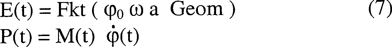
6) Der momentane Energiegehalt E(t) des FKW läßt sich
oft explizit ausdrücken,
und die momentane Gesamtantriebsleistung P(t) ergibt sich z.B. bei
der reinen Rotation (s = 0) aus Glg (7); sämtlichen Momentanwerte müssen im
allgemeinen numerisch integriert werden 6) The instantaneous energy content E (t) of the HFC can often be expressed explicitly, and the instantaneous total drive power P (t) results, for example, in the case of pure rotation (s = 0) from Eq (7); all instantaneous values must generally be numerically integrated
-
7) Schließlich
setzt sich die am Profil wirkende momentane Gesamt-Horizontalkraft
H(t) stets aus einem Trägheits-
und einem zirkulatorischen Teil zusammen; ihr über T zeitlich gemittelter
Wert Hm ergibt sich aus der Integration
Glg (8) Sämtliche Momentangrößen werden in ähnlicher Weise i.a. numerisch integriert. Der Mittelwert Hm wird zweckmäßig mit Hilfe der mittleren Profildurchströmgeschwindigkeit vm dimensionslos gemacht
 7) Finally, the instantaneous total horizontal force H (t) acting on the profile is always composed of an inertial and a circulatory part; its value H m averaged over T results from the integration Eq (8)
 All instantaneous sizes are generally integrated numerically in a similar way. The mean value H m is expediently made dimensionless with the aid of the mean profile flow velocity v m
 -
9) Abschließend
eine Bemerkung zu dem FKW, der in guter Näherung als RANKINE-Wirbel betrachtet
werden kann. Die radiale Geschwindigkeitsverteilung in der "Wirbelwalze"
ist also außen
logarithmisch (am Außenrand
selber mit dem Radius a herrscht Max vPRN)
und innen linear. Die mechanische Wirkung, d.h. das äquivalente,
axiale Massenträgheitsmoment θe des RANKINE-Wirbels ergibt sich mit dem
experimentell ermittelten Faktor n ein fD =
1,9796 für
die Glg (9) 9) Finally, a comment on the HFC, which can be regarded as a RANKINE vortex to a good approximation. The radial speed distribution in the "whirling roller" is therefore logarithmic on the outside (Max v PRN prevails on the outer edge itself with radius a) and linear on the inside. The mechanical effect, ie the equivalent, axial mass moment of inertia θ e of the RANKINE vertebra results from the experimentally determined factor n af D = 1.9796 for Eq (9)

Als Anwendungsbeispiel für die beschriebenen
Gleichungen der FVM zeigt 
- 1. Der Radius a ist unabhängig von f (er steigt nur mit φ0, Vgl. Exp. mit variierendem ω [5], d.h. in diesem Ansatz bleibt a konstant1. The radius a is independent of f (it only increases with φ 0 , cf. Exp. With varying ω [5], ie in this approach a remains constant
- 2. Der Radius a fällt linear mit f nach den experimentellen Befunden [8] ab, d.h. in diesem Ansatz ist a = a(f) variabel2. The radius a falls linear with f according to the experimental findings [8], i.e. in this The approach is a = a (f) variable
Beide Rechnungen (Frequenz 25 Hz
konstant) ergeben die charakteristischen, in
- – Für φ0 = 20° ist Cm = 29,10 (Hm = 0,210 N) und vm = 0,548 m/s, die notwendige Antriebs-Leistung wird Pm = 2,39 W- For φ 0 = 20 ° C m = 29.10 (H m = 0.210 N) and v m = 0.548 m / s, the necessary drive power becomes P m = 2.39 W.
- – Für φ0 = 40° ist Cm = 20,92 (Hm = 0,604 N) und vm = 1,097 m/s, die notwendige Antriebs-Leistung wird Pm = 9,56 W- For φ 0 = 40 ° C m = 20.92 (H m = 0.604 N) and v m = 1.097 m / s, the necessary drive power becomes P m = 9.56 W.
- – Mit größeren Amplituden φ0 wird höherer Vortrieb erzielt. Der Punkt Cm = 0 (Vortrieb = Widerstand wird für φ0 = 20° bei f ≅ 0,40 und für φ0 = 40° bei f ≅ 0,25 erreicht- Greater propulsion is achieved with larger amplitudes φ 0 . The point C m = 0 (propulsion = resistance is achieved for φ 0 = 20 ° at f ≅ 0.40 and for φ 0 = 40 ° at f ≅ 0.25
- – Die größten Vortriebskräfte werden unterhalb f ≤ 0,25 bzw 5 0,40 erzielt (schwache oder Null-Anströmung bzw. sogar "Rückenwind" vinf < 0)- The greatest propulsive forces are achieved below f ≤ 0.25 or 5 0.40 (weak or zero inflow or even "tail wind" v inf <0)
Mit den programmierten Glg (1) bis (9) sind sehr allgemeine Parametervariationen einfach und schnell durchgeführt worden, wobei neue Zusammenhänge sowie eine Reihe von technischen Anwendungen sichtbar geworden sind. Die beiden folgenden Kapitel 4. und 5. mit Erfindungsmeldungen für den Turbomaschinenbau (TM) basieren auf dem beschriebenen FVM mit der zugehörigen Berechnung.With the programmed Glg (1) to (9) very general parameter variations have been carried out simply and quickly, taking new contexts as well as a number of technical applications have become visible. The following two chapters 4. and 5. with inventions for turbomachinery (TM) are based on the described FVM with the associated calculation.
4. WIRBELERZEUGER4. SWIRLING GENERATOR
Bisherige experimentelle Arbeiten sowie TM-Anwendungen der instationären Aerodynamik verwenden als Wirbel- und Turbulenz-Erzeuger sog. "passive" Einrichtungen mit relativ hohem Druckverlust [9] bis [12]Previous experimental work and TM applications of transient aerodynamics are used the so-called "passive" devices with relatively high pressure loss as vortex and turbulence generators [9] to [12]
- – WIDERSTANDSKÖRPER, hinter denen sich unter bestimmten Voraussetzungen infolge vinf klassische v. KARMAN-Wirbelstraßen bilden: Periodische Ablösung von jeweils zwei gegensinnig drehenden Widerstandswirbeln, die fast gleichzeitig entstehen; ihre Frequenz und Amplitude (Stärke) ist nicht frei einstellbar- RESISTANCE BODY behind which under certain conditions as a result v inf classic v. KARMAN vortex streets form: Periodic replacement of two oppositely rotating resistance vortices that arise almost simultaneously; their frequency and amplitude (strength) cannot be freely adjusted
- – "SPEICHENRÄDER" zur Widerstands-gleichen Simulation von Laufschaufel-Nachläufen, d.h. vor dem Gittereinlauf rotierende, ca. 2 bis 5 mm dünne, radiale Stabzylinder: Die ersten Gitter-Leit-Reihen sehen periodische Geschwindigkeits-Defizite ("Dellen") mit relativ hoher Frequenz (typische Passage-Frequenzen, d.h. Drehzahl x Stabzahl liegen bei 1000 bis 5000 Hz) sowie eher geringen Amplituden- "SPOKED WHEELS" for Resistance-identical simulation of blade run-ons, i.e. in front of the grating inlet, rotating, approx. 2 to 5 mm thin, radial Rod cylinder: The first grid-guide rows see periodic speed deficits ("Dents") with a relatively high frequency (typical passage frequencies, i.e. Speed x number of bars are 1000 to 5000 Hz) and rather low amplitudes
- – "TURBULENZGITTER" zur künstlichen Erhöhung der Freistromturbulenz von Tu = ca. 2% auf 10 bis 30%- "TURBULENCE GRILL" for artificial increase free flow turbulence from Tu = approx. 2% to 10 to 30%
Hier hingegen werden die "aktiven",
in
Gegenüber den genannten passiven Wirbelerzeugern kommen hier folgende Vorteile sowohl im laminaren wie im turbulenten Fall zum TragenCompared to the passive mentioned Vortex generators here have the following advantages both in laminar as in the turbulent case
- 1) Erzeugung zweier kräftiger (Energiegehalt) gegensinnig drehender FKW je Periode in einem deutlichen zeitlichen Abstand T/21) Generation of two strong (energy content) in opposite directions rotating HFC per period at a clear time interval T / 2
- 2) Geringer (dynamischer) Widerstand bzw. Druckverlust, hohe cA-Werte [7]2) Low (dynamic) resistance or pressure loss, high c A values [7]
-
3) Starke Sogzone "S" durch den Kantenmechanismus (
1 ), verbesserte Profilaerodynamik [5]3) Strong suction zone "S" due to the edge mechanism (1 ), improved aerodynamics [5] - 4) Günstige, reibungsarme, "geschichtete" Wandströmungs-Struktur : Die Mantelströmung legt sich um die Grenzschicht [6]4) Cheap, Low-friction, "layered" wall flow structure: The jacket flow sets around the boundary layer [6]
- 5) Beschleunigte, in der Phase tH stabilisierte Grenzschicht auf der Saugseite mit verzögertem bzw. verhindertem Abreißen ("Dynamic Stall" [2])5) Accelerated boundary layer stabilized in phase t H on the suction side with delayed or prevented tearing ("Dynamic Stall" [2])
Zur möglichst effizienten Gestaltung
der vorgeschlagenen Wirbelerzeuger folgen direkt aus den expliziten
Gleichungen im Kap. 3. sieben wichtige, z.T. aus
- a) Hohe Geschwindigkeiten vPRN(t) über möglichst lange Zeiträume, hohes vmax ; Dies läßt sich z.B. durch verschiedene Kombinationen von 3 (a) mit 3 (b) erreichen ("Hover Modes" [4]), wobei die Rechnung zeigt, daß ein zeitlicher 90°-Vorlauf der Rotation φ(t) gegenüber der Translation optimal ist [8]a) High speeds v PRN (t) over long periods of time, high v max ; This can be achieved, for example, by various combinations of 3 (a) with 3 (b) ("hover modes" [4]), the calculation showing that a 90 ° advance of the rotation φ (t) is optimal compared to translation is [8]
- b) Lange HK-Erstreckung (hohes B); scharfe Profil-HK (kleiner Radius) für hohen Vortrieb/Auftrieb und Förderwirkungb) Long HK extension (high B); sharp profile HK (smaller Radius) for high propulsion / buoyancy and promotional effect
- c) Für hohe, positive cA,V-Werte darf die Kreisfrequenz ω der Profilschwingung nicht zu hoch (genügend Zeit zum Aufrollen des FKW/Aufbau von T) und nicht zu klein sein (Vortrieb/Auftrieb bzw. Fluid-Förderwirkung hoch)c) For high, positive c A, V values, the angular frequency ω of the profile vibration must not be too high (enough time for the HFC to roll up / build up of T) and not too small (propulsion / buoyancy or fluid delivery effect high)
- d) Ähnliches gilt für die Schwingungs-Amplituden φ0, s0: Mit Rücksicht auf die Begrenzung des dynamischen Widerstandes insbesondere bei hohem, vorgegebenem vinf sollten für cv > 0 die Amplituden eher begrenzt sein; andererseits steigen Vortrieb/Auftrieb und Förderwirkung mit φ0, s0 auch and) The same applies to the oscillation amplitudes φ 0 , s 0 : In view of the limitation of the dynamic resistance, in particular with a high, predetermined v inf , the amplitudes should be rather limited for c v >0; on the other hand, propulsion / buoyancy and support effect also increase with φ 0 , s 0
- e) Optimale zeitliche Pulsform, z.B. "ansteigendes Dreieck" o.ä. statt harmonischer Schwingung ; (lange Haftungsphase tH , hoher Vortrieb/Auftrieb)e) Optimal pulse shape over time, eg "rising triangle" or similar instead of harmonic vibration; (long liability phase t H , high propulsion / buoyancy)
- f) Je nach der speziellen Anwendung des Wirbelerzeugers (Fördern, Wirkungsgrad, Kühlen, Mischen) sind folgende Größen individuell zu optimieren : Schwingfrequenz, Amplituden, Drehpunkt der Profilrotation (z.B. 1/4-Sehnen-Punkt), Profilqualität u.a.f) Depending on the specific application of the vortex generator (conveying, efficiency, Cool, Mix) the following sizes are individual to optimize: vibration frequency, amplitudes, pivot point of the profile rotation (e.g. 1/4 tendon point), profile quality et al
-
g) Unter Umständen
ist die Nachschaltung eines Wirbel -Tilgers ("Stator") nach dem
Wirbel-Erzeuger ("Rotor") sinnvoll (Vgl.
8 )g) It may be useful to add a vortex eliminator ("stator") after the vortex generator ("rotor") (see8th )
Das FVM erlaubt Optimierungen in
weiten Anwendungsbereichen, wobei nach Erfahrungen im Schwingungs-Maschinenbau
die vorgeschlagenen Wirbelerzeuger in
Die einfachsten Anordnungen in ![]()
![]()
![]()
![]()
5. ANWENDUNGEN5. APPLICATIONS
Die Erprobung des FVM erfolgte durch
erfolgreiche Nachrechnung von 12 sehr unterschiedlichen, vollständig definierten
Experimenten in Luft und Wasser [
Die im Folgenden beschriebenen vier Erfindungsmeldungen betreffen speziell den Bau stationärer Gasturbinen (GT), können aber auch generell im Turbomaschinenbau angewandt werden.The four described below Invention reports relate specifically to the construction of stationary gas turbines (GT), can but are also generally used in turbomachinery.
5.1 FÖRDERN VON FLUIDEN5.1 CONVEYING FLUIDS
Analog zur Propulsion [6] (ruhendes
Fluid, bewegtes Antriebssystem) wird beim Fördern durch Rohrleitungen das
Fluid effizient, d.h. Druckverlust-arm von einem ruhenden System
aus Wirbel-Erzeugern und -Tilgern in Bewegung gesetzt. Ziel ist
hier, mit geringer Antriebs-Leistung Pm,
den mittleren bezogenen Massenstrom ![]()
![]()
![]()
![]()
Im Einzelnen zeigt
![]()
![]()
Neben anderen Anwendungen können die
Fördersysteme
- a) Steigerung der Effizienz diverser Kühlluftströme, speziell Reduktion des Druckbedarfes dieser Verdichter-Entnahmeströme infolge der effizienten Pumpwirkung der Wirbel-Erzeugera) Increasing the efficiency of various cooling air flows, especially Reduction in the pressure requirement of these compressor extraction flows as a result the efficient pumping action of the vortex generators
- b) Kombination von a) mit einer höheren Kühleffektivität dieser Külluftströme in den innengekühlten Turbinen-Schaufeln (Vgl. Kap. 5.3)b) Combination of a) with a higher cooling effectiveness of this Cooling air flows in the internally cooled Turbine blades (see chapter 5.3)
- c) Möglichkeit, den für die Filmkühlung notwendigen Brennkammer-Druckverlust zu senkenc) possibility the for the film cooling reduce the necessary combustion chamber pressure loss
-
d) Reduktion des Druckverlustes der Verdichter-Eintrittsreihe
durch eine "aktive" Ausführung
gemäß
6(a) bzw.4(a) d) Reduction of the pressure loss of the compressor inlet row by an "active" design according to6 (a) respectively.4 (a)
5.2 GITTERSTRÖMUNGEN5.2 GRID FLOWS
Die Anordnung effizienter Wirbelerzeuger
vor dem Einlauf axialer TM-Gitter,
- – Erhöhung des mittleren V-Gitterwirkungsgrades ηm - Increasing the mean V-lattice efficiency η m
- – Erhöhung der Stufenbelastung bzw. Reduktion der Schaufelzahl pro Reihe- increase in Step loading or reduction of the number of blades per row
- – Erhöhung des Pumpabstandes und bessere Teillastfähigkeit- increase in Pump distance and better partial load capacity
Bei hydraulischen TM kommt hinzu, daß man größere NPSH-Reserven bekommt ("Net Positive Suction Head") und damit Kavitation vermeidet.With hydraulic TM there is also that he larger NPSH reserves gets ("Net Positive Suction Head") and thus avoids cavitation.
Ziel bei Gitterströmungen ist
es, gemäß ![]()
![]()
- A) Die Verbesserung der Le0-Profil-Aerodynamik durch periodisch instationäre HK-Umströmung (hohe cA-Werte, geringer Druckverlust); die effiziente Erzeugung geeigneter Strömungspulse für die stromab-GitterströmungA) The improvement of the Le0 profile aerodynamics through periodically unsteady HK flow (high c A values, low pressure loss); the efficient generation of suitable flow pulses for the downstream grid flow
- B) Die Plazierung der stromab Leitschaufel-Reihen in sog. "Clocking"-Positionen" [9][10] und die "maßgeschneiderte" Puls-Erzeugung ermöglichen eine optimale Nutzung der periodisch durch die Grenzschichten laufenden FluktuationenB) The placement of the downstream guide vane rows in so-called "clocking" positions " [9] [10] and the "bespoke" Enable pulse generation optimal use of the periodically running through the boundary layers fluctuations
Bekannt ist (Vgl. Ref [C][9]), daß bereits die im Eintritt entstehenden "stationären" Schaufel-Nachläufe in den Clocking-Folgestufen eine Erhöhung des ηm um ca. 1,0 % Punkte bewirken. Weiterhin ist erkannt worden [11], daß sich beim Durchlauf instationärer Pulse durch ein Gitter laminare ebenso wie turbulente Grenzschichten wie "trägheitsarme Oszillatoren" verhalten, welche die Fluktuationen verstärken und sowohl die Grenzschicht-Entwicklung als auch Ort und Zeit des laminar → turbulenten Umschlags beeinflussen.It is known (cf. Ref [C] [9]) that the "stationary" blade wakes that arise in the inlet in the subsequent clocking stages result in an increase in the η m of approximately 1.0% points. It has also been recognized [11] that when transient pulses pass through a grating, laminar as well as turbulent boundary layers behave like "low-inertia oscillators", which increase the fluctuations and influence both the boundary layer development and the location and time of the laminar → turbulent change ,
Es ist mindestens ein gleicher, wenn
nicht größerer Vorteil
der energiereicheren FKW-Pulse gemäß A) zu erwarten : Nach
- – Art der Erzeugung von stromauf-Strömungspulsen bzw. Nachläufen von "Speichenrädern"- Art the generation of upstream flow pulses or wakes of "spoke wheels"
- – Frequenz der durchlaufenden Wirbel bzw. Passage-Frequenz des Speichenrades- frequency the continuous vortex or passage frequency of the spoke wheel
- – Pulsstärke, d.h. Druck-/Geschwindigkeits-/Energie-Amplituden bzw. Geschwindigkeits-Defizit bei Passage einer Speiche- pulse strength, i.e. Pressure / speed / energy amplitudes or speed deficit when passing a spoke
- – Breite und Einwirkdauer der Fluktuationen- width and exposure time of the fluctuations
- – Schaufelbelastung, Abström-Reynoldszahl- bucket load, Abström Reynolds number
Mit dem nach
-
1) Erzeugung intensiver Einzelwirbel mit Frequenzen
und Amplituden, die in weiten Grenzen kontinuierlich frei wählbar sind;
abwechselnde Entstehung von Turbulenz- und Beruhigungs-Zonen in
den stromab-Grenzschichten (unterdrückte Strömungsablösung) [
10] 1) Generation of intensive single vortices with frequencies and amplitudes that can be freely selected within wide limits; alternating development of turbulence and calming zones in the downstream boundary layers (suppressed flow separation) [10] - 2) Separate Erzeugung diskreter FKW in der Le0 in genügendem zeitlichen Abstand T/2, so daß ausreichend Zeit verfügbar ist für den Aufbau von Kantenwirbeln und "Blasen" an den stromab-Schaufel-Vorderkanten und -HK2) Separate generation of discrete HFCs in Le0 at a sufficient time interval T / 2 so that they are sufficient Adequate time is available for the build-up of edge vortices and "bubbles" on the downstream blade leading edges and -HK
- 3) Reduzierter Gesamtwiderstand/verbesserte Aerodynamik der Eintrittsreihe Le0 bei geringer Antriebsleistung Pm 3) Reduced total resistance / improved aerodynamics of the entrance row Le0 with low drive power P m
-
4) Frei wählbare
weitere Einflußparameter
wie Pulsform, Drehpunkt von φ(t)
etc. (Vgl. Kap. 4,
1 )4) Freely selectable other influencing parameters such as pulse shape, pivot point of φ (t) etc. (see Chapter 4,1 )
5.3 BAUTEILKÜHLUNG5.3 COMPONENT COOLING
Man kann den Wärme- und Stoff-Austausch quer zu einer Hauptströmung durch Erhöhung der Strömungsgeschwindigkeit steigern; eine weitere Steigerung ist aber auch durch Aufprägen von Geschwindigkeits-Schwankungen auf den stationären Kühlstrom möglich. Neuere Messungen belegen z.T. starke Erhöhungen des mittleren Wärmeübergangskoeffizienten am (bis zu 27 %) [12] bis [14]; dabei sind bisher Fluktuationen eingesetzt worden, die von Schockwellen, von Erhöhungen des Turbulenzgrades (Tu = 2% auf ca. 20%) oder von Speichenrädern (Nachlauf-Simulation) vor Gittern herrühren. Die Erzeugung dieser Art von Fluktuationen kostet jedoch meistens hohe Druckverluste, die man vermeiden will.One can increase the heat and material exchange across a main flow by increasing the flow velocity; a further increase is also possible by impressing speed fluctuations on the stationary cooling flow. Recent measurements show strong increases in the mean heat transfer coefficient a m (up to 27%) [12] to [14]; fluctuations have so far been used which result from shock waves, from increases in the degree of turbulence (Tu = 2% to approx. 20%) or from spoke wheels (caster simulation) in front of bars. However, the generation of this type of fluctuation usually costs high pressure losses that you want to avoid.
Bei der Bauteilkühlung – speziell bei der effizienten
Kühlung
von GT-Heißteilen – zielt
man darauf ab, geeignete Strömungsfluktuationen
ohne nennenswerte Druckverluste sowie Antriebsleistungen zu erzeugen; die
charakteristischen Parameter dieser Schwankungen sind so zu wählen, daß der mittlere
bezogene Wärmeübergangskoeffizient
nach Glg (12) maximiert wird ![]()
![]()
Dafür wird statt der o.g. Elemente
der Einsatz der in
- – Periodische Entstehung von Schwankungs- und Beruhigungs-Zonen [10] [11]- Periodic Development of fluctuation and calming zones [10] [11]
- – Verstärkung dieser Fluktuationen durch Grenzschicht-Reaktionszeiten, die sehr klein sind gegenüber der Einwirkzeit der aufgeprägten Schwankungen selber (Vgl. [11] und Kap. 5.2)- reinforce this Fluctuations due to boundary layer response times that are very small are opposite the exposure time of the embossed Fluctuations themselves (see [11] and section 5.2)
- – Synchron dazu schwanken die Gradienten von w(y) an der Wand innerhalb der δ(t) sowie die örtlichen Wärmeübergangskoeffizienten α(t)- Synchronous the gradients of w (y) on the wall fluctuate within the δ (t) as well the local heat transfer coefficients α (t)
Nach heutiger Kenntnis ist vor allem die stromauf-Verschiebung des laminar → turbulenten Umschlagpunktes an der Wand der Grund für die resultierenden folgenden Effekte [12], die bei der GT-Heißteilkühlung zu erwarten sindAccording to today's knowledge is above all the upstream shift of the laminar → turbulent transition point on the wall the reason for the resulting following effects [12], which increase with GT hot part cooling are expected
- 1) Deutliche Erhöhung des mittleren Wärmeübergangskoeffizienten am bei niedrigem (pV)m1) Significant increase in the mean heat transfer coefficient at at low (p V ) m
- 2) Und damit eine Verbesserung gemäß Glg (12) sowohl bei konvektiver (αk(t)) als auch bei Prallkühlung (αp(t)) von Brennkammerteilen, wie bei der Innenkühlung (inkl. Filmkühlung) von Turbinenschaufeln2) And thus an improvement according to Eq. (12) both with convective (α k (t)) and with impingement cooling (α p (t)) of combustion chamber parts, such as with the internal cooling (including film cooling) of turbine blades
-
3) Bei Prallkühlung
ist zusätzlich
zu erwarten, daß die
schädliche
"Welligkeit" infolge der "Jets" durch Fluktuationen verringert wird
(Vgl.
7(b) )3) In the case of impingement cooling, it is additionally to be expected that the harmful "ripple" due to the "jets" will be reduced by fluctuations (cf.7 (b) ) - 4) Aus 1) bis 3) folgen höhere Kühleffektivitäten und Wärmestromdichten an der Heißgas-benetzten Wand; für gleiche zulässige Wandtemperaturen resultiert somit eine Kühlluftersparnis4) From 1) to 3) follow higher ones Cooling effects and Heat fluxes on the hot gas-wetted Wall; For same permissible Wall temperatures thus result in a cooling air saving
Die geschilderte Kühlluft-Einsparung sowohl im Brennkammer- wie im Turbinen-Schaufel-Bereich von GT ermöglicht die Kombination vonThe cooling air savings described this enables both in the combustion chamber and in the turbine blade area of GT combination of
- - Leistungs-Erhöhungen- Performance increases
- - Wirkungsgrad-Erhöhungen- efficiency increases
- - Absenkungen der NOx-Emission- Reductions in NO x emissions
Insbesondere kann eine Verbindung
der effizienten Kühlluft-Fördersysteme
Die in
5.4 MISCHEN VON FLUIDSTRÖMEN5.4 MIXING FLOW FLOWS
Aufgeprägte Geschwindigkeits-Schwankungen
erhöhen
nicht nur den Wärmesondern
auch den Stoff-Austausch quer zur Hauptströmung, so daß die Vorschläge zur Bauteilkühlung (Kap.
5.3) sinngemäß auch für das effiziente
Mischen von Fluidströmen,
z.B. "I" und "II" in ![]()
![]()
Die in
Als Antrieb AN an den Kanalseiten
ist in
Die vorgeschlagene Misch-Strecke hat ihren Anwendungsschwerpunkt sicher in der Verfahrenstechnik u. ä.; im Gasturbinenbau sind zwei denkbare Anwendungen zu nennen, bei denen es speziell auf Druckverlust-arme, vollständige Mischung ankommtThe proposed mixing route has its main application in process engineering u. etc .; in gas turbine construction there are two conceivable applications, at for whom a low-loss, complete mixture is particularly important
- – Vormischung von Luft und Erdgas vor der Verbrennung (Ziel : Reduktion der NOx-Emissionen)- premixing of air and natural gas before combustion (goal: reduction of NO x emissions)
- – Bildung gleichmäßiger Emulsionen aus leichtem Heizöl und Wasser für die NOx-arme Verbrennung- formation of uniform emulsions domestic heating fuel and water for the low NOx combustion
7.
NOMENKLATUR 


8. REFERENZEN8. REFERENCES
- [1] POLING, D.R., TELIONIS, D.P.: "The response of airfoils to pertodic disturbances – the unsteady KUTTA condition",AIAA JournaI,Vo1.24,No.2, 1989, pp. 193-199[1] POLING, D.R., TELIONIS, D.P .: "The response of airfoils to pertodic disturbances - the unsteady KUTTA condition ", AIAA JournaI, Vo1.24, No.2, 1989, pp. 193-199
- [2] Mc CROSKEY, W.J., Mc ALISTER, K.W., CARR, L.W.: "Dynamic stall expertments on oscillating airfoils",AIAA Journal,Vo1.14,No.1,1976,pp.57-63[2] Mc CROSKEY, W.J., Mc ALISTER, K.W., CARR, L.W .: "Dynamic stall expertments on oscillating airfoils ", AIAA Journal, Vo1.14, No.1,1976, pp.57-63
- [3] SONDAK, DORNEY : "Simulation of vortex shedding in a turbine stage", ASME Conf. 1998, paper 98-GT-242[3] SONDAK, DORNEY: "Simulation of vortex shedding in a turbine stage ", ASME Conf. 1998, paper 98-GT-242
- [4] FREYMUTH, P., GUSTAFSON, K.E., LEBEN, R.: "Visualization and computation of hovering mode", (in "Vortex Methods"), Phil./Pa., USA, SIAM,1991[4] FREYMUTH, P., GUSTAFSON, K.E., LEBEN, R .: "Visualization and computation of hovering mode ", (in" Vortex Methods "), Phil./Pa., USA, SIAM, 1991
- [5] LIEBE, W.: "Der Schwanzschlag der Fische", VDI-Zeitschrift, Band 105 ,Nr.28, VDI-Verlag Düsseldorf, 1963, S. 1298 ff.[5] LOVE, W .: "The tail blow of the fish", VDI magazine, Volume 105, No. 28, VDI-Verlag Düsseldorf, 1963, P. 1298 ff.
- [6] LIEBE, W.: "Die schwingende Hinterkante als Auftrtebshilfe und zur Verminderung des Widerstands am Tragflügel", DGLR-Tagung, Berlin, 1999[6] LOVE, W .: "The swinging trailing edge as a step aid and to reduce drag on the wing ", DGLR conference, Berlin, 1999
- [7] LIEBE, W., LIEBE, R.: "A general finite vortex model to describe unsteady aerodynamics in nature", 1st Internat. Conference "Design & Nature 2002", Udine/Italy, 2002[7] LIEBE, W., LIEBE, R .: "A general finite vortex model to describe unsteady aerodynamics in nature", 1 st boarding school. Conference "Design & Nature 2002", Udine / Italy, 2002
- [8] LIEBE, R.: "Validation of the finite vortex model by analyzing unsteady aerodynamic experiments", 1st Internat. Conference "Design & Nature 2002", Udine /Italy, 2002[8] LIEBE, R .: "Validation of the finite vortex model by analyzing unsteady aerodynamic experiments", 1 st boarding school. Conference "Design & Nature 2002", Udine / Italy, 2002
- [9] HEINKE, W., STOFFEL, B. et al.: "Numertsche Simulation und experimentelle Untersuchungen zum Clocking-Effekt", 7. Seminar der AG TURBO, Köln, DLR, Nov. 2000, S.11-1 ff[9] HEINKE, W., STOFFEL, B. et al .: "Numerical simulation and experimental studies on the clocking effect ", 7th seminar of the AG TURBO, Cologne, DLR, Nov. 2000, pp. 11-1 ff
- [10] SCHIFFER, H.P., FOTTNER, L. et al.: "Hochbelastete, ungekühlte Turbinenbeschaufelung mit instationärer Zuströmung", 7.Seminar der AG TURBO, Kö1n, DLR, Nov. 2000, S. 5-1 bis 5-16[10] SCHIFFER, H.P., FOTTNER, L. et al .: "Heavy-duty, uncooled turbine blading with transient Inflow " 7th seminar of AG TURBO, Kö1n, DLR, Nov. 2000, pp. 5-1 to 5-16
- [11] ELSNER, W., STANISLAW, D.: "The nonstationary behaviour of stator profile boundary layer excited by pertodic upstream wakes", Proc. of ASME TURBO EXPO 2002, paper GT-2002-30234, Amsterdam INL, June 2002[11] ELSNER, W., STANISLAW, D .: "The nonstationary behavior of stator profile boundary layer excited by pertodic upstream wakes ", Proc. of ASME TURBO EXPO 2002, paper GT-2002-30234, Amsterdam INL, June 2002
- [12] DULLENKOPF, K., SCHULZ, A., WITTIG, S.: "Einfluß periodisch instationärer Zuströmbedingungen auf den zeitlich gemittelten Wärmeübergang an Turbinenschaufeln", 2. Seminar der AG Hochtemperatur-Gasturbine, Köln, DLR, 1990 [12] DULLENKOPF, K., SCHULZ, A., WITTIG, S .: "Periodic influence unsteady inflow conditions on the time-averaged heat transfer on turbine blades ", 2nd seminar of the AG high-temperature gas turbine, Cologne, DLR, 1990
- [13] LEE, S.W. et al.: "Effects of high free-stream turbulence on the near-wa11-flow and heat /mass transfer on the endwall of a linear turbine rotor cascade", Proc. of ASME TURBO EXPO 2002, paper GT-2002-30187, Amsterdam /NL, June 2002[13] LEE, S.W. et al .: "Effects of high free-stream turbulence on the near-wa11-flow and heat / mass transfer on the endwall of a linear turbine rotor cascade ", Proc. of ASME TURBO EXPO 2002, paper GT-2002-30187, Amsterdam / NL, June 2002
- [14] DIDER, F., DENOS, R., ARTS, T.: Unsteady rotor heat transfer in a transsonic turbine stage", Proc. of ASME TURBO EXPO 2002, paper GT-2002-30195, Amsterdam/NL, June 2002[14] DIDER, F., DENOS, R., ARTS, T .: Unsteady rotor heat transfer in a transsonic turbine stage ", Proc. of ASME TURBO EXPO 2002, paper GT-2002-30195, Amsterdam / NL, June 2002
8.2 PATENTE8.2 PATENTS
- [A] BRD-Patent 900 526, W.LIEBE, Berlin /Deutschland: "Förderklappe für Flüssigkeiten", Juni 1951[A] FRG patent 900 526, W.LIEBE, Berlin / Germany: "Conveyor flap for liquids ", June 1951
- [B] US Patent 3,475,108 ; W. ZICKUHR, Mülheim /Deutschland :"Blade structure for turbines", February 1968[B] US Patent 3,475,108; W. ZICKUHR, Mülheim / Germany: "Blade structure for turbines ", February 1968
- [C] US Patent 5,486,091 ; O. P. SHARMA,/USA: "Gas turbine airfoil clocking", January 1996[C] US Patent 5,486,091; O. P. SHARMA, / USA: "Gas turbine airfoil clocking ", January 1996
9. ABBILDUNGEN9. PICTURES
Claims (5)
Priority Applications (7)
| Application Number | Priority Date | Filing Date | Title |
|---|---|---|---|
| DE10237341A DE10237341A1 (en) | 2002-08-14 | 2002-08-14 | Finite vortex model for use in fluid flow numerical simulation, especially for modeling unsteady flows, whereby a general roll-off model is used to model the finite edge vortex |
| DE50311668T DE50311668D1 (en) | 2002-08-14 | 2003-08-12 | DEVICE FOR GENERATING SPINS AND METHOD FOR OPERATING THE DEVICE |
| US10/523,512 US7431244B2 (en) | 2002-08-14 | 2003-08-12 | Device for the generation of eddies and method for operating of said device |
| PCT/DE2003/002721 WO2004020841A1 (en) | 2002-08-14 | 2003-08-12 | Device for the generation of eddies and method for operation of said device |
| CNB038173182A CN1325807C (en) | 2002-08-14 | 2003-08-12 | Device for the generation of eddies and method for operation of said device |
| EP03790717A EP1529169B1 (en) | 2002-08-14 | 2003-08-12 | Device for the generation of eddies and method for operation of said device |
| ES03790717T ES2326219T3 (en) | 2002-08-14 | 2003-08-12 | DEVICE FOR GENERATING TORBELLINOS AS WELL AS A PROCEDURE TO OPERATE THE DEVICE. |
Applications Claiming Priority (1)
| Application Number | Priority Date | Filing Date | Title |
|---|---|---|---|
| DE10237341A DE10237341A1 (en) | 2002-08-14 | 2002-08-14 | Finite vortex model for use in fluid flow numerical simulation, especially for modeling unsteady flows, whereby a general roll-off model is used to model the finite edge vortex |
Publications (1)
| Publication Number | Publication Date |
|---|---|
| DE10237341A1 true DE10237341A1 (en) | 2004-02-26 |
Family
ID=30775289
Family Applications (2)
| Application Number | Title | Priority Date | Filing Date |
|---|---|---|---|
| DE10237341A Withdrawn DE10237341A1 (en) | 2002-08-14 | 2002-08-14 | Finite vortex model for use in fluid flow numerical simulation, especially for modeling unsteady flows, whereby a general roll-off model is used to model the finite edge vortex |
| DE50311668T Expired - Lifetime DE50311668D1 (en) | 2002-08-14 | 2003-08-12 | DEVICE FOR GENERATING SPINS AND METHOD FOR OPERATING THE DEVICE |
Family Applications After (1)
| Application Number | Title | Priority Date | Filing Date |
|---|---|---|---|
| DE50311668T Expired - Lifetime DE50311668D1 (en) | 2002-08-14 | 2003-08-12 | DEVICE FOR GENERATING SPINS AND METHOD FOR OPERATING THE DEVICE |
Country Status (6)
| Country | Link |
|---|---|
| US (1) | US7431244B2 (en) |
| EP (1) | EP1529169B1 (en) |
| CN (1) | CN1325807C (en) |
| DE (2) | DE10237341A1 (en) |
| ES (1) | ES2326219T3 (en) |
| WO (1) | WO2004020841A1 (en) |
Cited By (4)
| Publication number | Priority date | Publication date | Assignee | Title |
|---|---|---|---|---|
| EP1514592A1 (en) * | 2003-09-11 | 2005-03-16 | Glunz Ag | Process and apparatus for static mixing, especially for the glueing of lignocellulosic fibers using a binder |
| EP1724440A1 (en) * | 2005-05-10 | 2006-11-22 | MTU Aero Engines GmbH | Process for optimizing the flow in multistage turbomachines |
| EP2025868A1 (en) * | 2007-08-10 | 2009-02-18 | Siemens Aktiengesellschaft | Turbine blade having a turbulator at the cooling air inlet |
| US9291177B2 (en) | 2010-06-01 | 2016-03-22 | Esg Mbh | Duct having flow conducting surfaces |
Families Citing this family (6)
| Publication number | Priority date | Publication date | Assignee | Title |
|---|---|---|---|---|
| FR2925106B1 (en) * | 2007-12-14 | 2010-01-22 | Snecma | METHOD FOR DESIGNING A TURBOMACHINE MULTI-STAGE TURBINE |
| CN103062138A (en) * | 2013-01-15 | 2013-04-24 | 上海大学 | Flow separation control device |
| AU2013375126A1 (en) * | 2013-01-25 | 2015-08-13 | Anthony IRELAND | Energy efficiency improvements for turbomachinery |
| CN109441554B (en) * | 2018-10-29 | 2021-01-19 | 中国民航大学 | Turbine blade suitable for aeroengine |
| US20220121124A1 (en) * | 2018-12-06 | 2022-04-21 | Asml Netherlands B.V. | Flow restriction, flow restriction assembly and lithographic apparatus |
| CN109859311B (en) * | 2019-01-29 | 2021-05-18 | 河海大学 | Simulation method based on Liutex-Omega vortex recognition theory |
Family Cites Families (21)
| Publication number | Priority date | Publication date | Assignee | Title |
|---|---|---|---|---|
| DE215155C (en) | ||||
| DE900526C (en) | 1951-06-16 | 1953-12-28 | Walter Ernst | Conveyor flap for liquids |
| US2813708A (en) * | 1951-10-08 | 1957-11-19 | Frey Kurt Paul Hermann | Devices to improve flow pattern and heat transfer in heat exchange zones of brick-lined furnaces |
| US2740596A (en) * | 1953-08-19 | 1956-04-03 | United Aircraft Corp | Vortex generator |
| GB763359A (en) * | 1954-01-21 | 1956-12-12 | Lucas Industries Ltd | Combustion chambers for jet propulsion engines, gas turbines or other apparatus |
| US2878831A (en) * | 1957-02-04 | 1959-03-24 | Farnham Rex Couvelas | Fluid control means |
| US3241771A (en) * | 1963-09-18 | 1966-03-22 | Gen Electric | Thrust deflector and reverser |
| US3475108A (en) * | 1968-02-14 | 1969-10-28 | Siemens Ag | Blade structure for turbines |
| US3986787A (en) * | 1974-05-07 | 1976-10-19 | Mouton Jr William J | River turbine |
| US4058141A (en) * | 1975-08-20 | 1977-11-15 | The United States Of America As Represented By The Secretary Of The Air Force | Supersonic flow diffuser with energy redistribution |
| AT387955B (en) * | 1981-01-13 | 1989-04-10 | Sneek Landustrie | DEVICE FOR DRIVING A LIQUID IN A CHANNEL |
| US4667900A (en) * | 1981-03-05 | 1987-05-26 | Kyusik Kim | Ram constriction vane diffuser for jet engine |
| FR2528500A1 (en) | 1982-06-11 | 1983-12-16 | Agronomique Inst Nat Rech | Silent ventilator unit for air conditioning system - uses flexible flap, in conduit, driven by electromagnet at resonant frequency of flap to displace air |
| DD215155A1 (en) * | 1983-05-05 | 1984-10-31 | Zittau Ing Hochschule | TURBULATOR AND METHOD FOR INCREASING THE HEAT TRANSFER |
| US4844382A (en) * | 1983-10-19 | 1989-07-04 | Raisbeck Engineering, Inc. | Dual turning vane air inlet assembly |
| DE3343296A1 (en) * | 1983-11-30 | 1985-06-05 | Theod. Mahr Söhne GmbH, 5100 Aachen | Device for regulating the volumetric flow in a flow passage |
| US5525269A (en) * | 1985-03-22 | 1996-06-11 | Philadelphia Gear Corporation | Impeller tiplets for improving gas to liquid mass transfer efficiency in a draft tube submerged turbine mixer/aerator |
| JPH03160200A (en) | 1989-11-15 | 1991-07-10 | Kenji Oe | Air blower |
| US5302092A (en) | 1991-06-07 | 1994-04-12 | Daikin Industries, Ltd. | Fluid transferring apparatus imitating flapping movement of bees |
| US5486091A (en) * | 1994-04-19 | 1996-01-23 | United Technologies Corporation | Gas turbine airfoil clocking |
| US7108569B2 (en) * | 2003-03-19 | 2006-09-19 | Cornell Donald E | Axial flow pump or marine propulsion device |
-
2002
- 2002-08-14 DE DE10237341A patent/DE10237341A1/en not_active Withdrawn
-
2003
- 2003-08-12 DE DE50311668T patent/DE50311668D1/en not_active Expired - Lifetime
- 2003-08-12 EP EP03790717A patent/EP1529169B1/en not_active Expired - Lifetime
- 2003-08-12 ES ES03790717T patent/ES2326219T3/en not_active Expired - Lifetime
- 2003-08-12 WO PCT/DE2003/002721 patent/WO2004020841A1/en not_active Application Discontinuation
- 2003-08-12 US US10/523,512 patent/US7431244B2/en not_active Expired - Fee Related
- 2003-08-12 CN CNB038173182A patent/CN1325807C/en not_active Expired - Fee Related
Cited By (5)
| Publication number | Priority date | Publication date | Assignee | Title |
|---|---|---|---|---|
| EP1514592A1 (en) * | 2003-09-11 | 2005-03-16 | Glunz Ag | Process and apparatus for static mixing, especially for the glueing of lignocellulosic fibers using a binder |
| EP1724440A1 (en) * | 2005-05-10 | 2006-11-22 | MTU Aero Engines GmbH | Process for optimizing the flow in multistage turbomachines |
| US7758297B2 (en) | 2005-05-10 | 2010-07-20 | Mtu Aero Engines Gmbh | Method for flow optimization in multi-stage turbine-type machines |
| EP2025868A1 (en) * | 2007-08-10 | 2009-02-18 | Siemens Aktiengesellschaft | Turbine blade having a turbulator at the cooling air inlet |
| US9291177B2 (en) | 2010-06-01 | 2016-03-22 | Esg Mbh | Duct having flow conducting surfaces |
Also Published As
| Publication number | Publication date |
|---|---|
| US7431244B2 (en) | 2008-10-07 |
| DE50311668D1 (en) | 2009-08-13 |
| EP1529169B1 (en) | 2009-07-01 |
| EP1529169A1 (en) | 2005-05-11 |
| CN1668853A (en) | 2005-09-14 |
| ES2326219T3 (en) | 2009-10-05 |
| US20060102799A1 (en) | 2006-05-18 |
| WO2004020841A1 (en) | 2004-03-11 |
| CN1325807C (en) | 2007-07-11 |
Similar Documents
| Publication | Publication Date | Title |
|---|---|---|
| DE3530769C2 (en) | Blade for a gas turbine engine | |
| DE1476796C3 (en) | A component of a gas turbine system made integrally from a high-strength material | |
| DE69829385T2 (en) | STAINLESS STEEL ENGINE WITH EJECTOR | |
| CH704302B1 (en) | Thrust generators Airplane method for generating thrust and method for improving the driving efficiency of an aircraft. | |
| DE10237341A1 (en) | Finite vortex model for use in fluid flow numerical simulation, especially for modeling unsteady flows, whereby a general roll-off model is used to model the finite edge vortex | |
| EP0846867A2 (en) | Turbomachine with a transsonic compression stage | |
| DE1934246A1 (en) | Boundary layer control for flow separation and heat exchange | |
| DE3614157C2 (en) | Gas turbine engine with counter-rotating propellers | |
| DE102009044585A1 (en) | A method, apparatus, and systems for circumferentially aligning turbine blades with respect to combustor tubes and cooling airflow through the turbine hot gas flowpath | |
| CH708774A2 (en) | The turbine blade having an airfoil with Spitzenausrundung. | |
| EP3631349B1 (en) | Recuperative jet propulsion | |
| Walker et al. | The effect of passive and active boundary-layer fences on swept-wing performance at low Reynolds number | |
| DE102020131807A1 (en) | GAS TURBINE ENGINE OPERATING MODE | |
| EP0937862B1 (en) | Arrangement of axial turbines blades | |
| DE60105737T2 (en) | Turbine blade arrangement | |
| DE3734624C2 (en) | ||
| EP3591237B1 (en) | Structural module for a compressor of a turbomachine | |
| DE102013109844A1 (en) | A method of circumferentially aligning a turbine by reshaping the downstream airfoils of the turbine | |
| DE2733986A1 (en) | POWER PLANT WITH DIFFERENTIAL GEAR | |
| Siddanathi | Application of co-flow jet concept to aircraft lift increase | |
| EP0448559B1 (en) | Lift-jet engine for independent operation or for use in an aircraft | |
| An et al. | Thickness effect on the thrust generation of heaving elliptic airfoils | |
| DE102019215150A1 (en) | Aerodynamic body and its uses | |
| DE3338286A1 (en) | AIRPLANE ENGINE GONDOLA AND METHOD FOR PRODUCING A PROFILE THEREOF | |
| DE3915725C2 (en) |
Legal Events
| Date | Code | Title | Description |
|---|---|---|---|
| 8139 | Disposal/non-payment of the annual fee |