Recycle vertical wind tunnel parachute jumping simulator and vertical wind tunnel free-falling simulator
The application of cross reference
The U.S. Patent Application Serial 11/184,940 that the application requires to submit to on July 19th, 2005 is as right of priority, and it is as the part continuation application of the U.S. Patent Application Serial 10/909,088 of submitting on July 30th, 2004.
Technical field
The application relates to the vertical wind tunnel field, more specifically to the temperature-control back flow vertical wind tunnel as parachute jumping simulator and entertainment device.
Background technology
Wind-tunnel is well-known in the prior art.Can obtain according to user's needs the wind-tunnel of many types and pattern.These wind-tunnel comprise subsonic wind tunnel, the transonic wind tunnel that has and do not have backflow that has and do not have backflow, the vertical subsonic wind tunnel that has and do not have backflow, the supersonic speed that has and do not have backflow and special supersonic wind tunnel and compressible mobile wind-tunnel.
Most of wind-tunnel are used to research and test purpose.These comprise test and other Basic Flow dynamic tests of orthodox flight device, helicopter, parachute and other air generation plantses, wing surface, control surface, submarine, rocket and other delivery vehicles, land vehicle, buildings.
Horizontal wind-tunnel (air the full speed section of wind-tunnel basically the wind-tunnel of horizontal flow) is used to aerodynamic studies and test, and is grasped by the company that usually is engaged in preferential defense, federal government or educational institution and university.Wherein some have been converted into or have been suitable for vertical operation (wind-tunnel that its Air vertically flows basically in the full speed section of wind-tunnel), but great majority in them or all in that respect effects are very poor.
Different from the horizontal checkout wind-tunnel to the design restriction that the vertical wind tunnel that is used to simulate free-falling applies.In vertical wind tunnel/free-falling simulator, importantly the object (being aloft people in this application) of section can be mobile everywhere in described section at full speed at wind-tunnel, with experience or the flight of experience human body.In the horizontal checkout wind-tunnel, the object of placing in wind-tunnel normally can be by the stationary body that other people observe or measure.For this reason, this fastest part of horizontal wind-tunnel is called as " test section ".In vertical wind tunnel, this same area be otherwise known as " flight cavity ".
In vertical wind tunnel, importantly can be in the situation that do not stop air-flow and the people who flies in the wind-tunnel is rotated in the flight capsule and rotate flight capsule.By contrast, need to move stationary body at the test section of horizontal wind-tunnel hardly in the operating process.In addition, because the aviator in the vertical wind tunnel is freely mobile in flight capsule, therefore their movement must be limited to the suitable part of system everywhere.
Although can all place safety net in upstream extremity and the downstream end of flight capsule, produce so huge resistance, thereby form noise and have increased access to the required power of any given speed.In fact, the power that so a pair of net can consume reaches the 30%-50% of the required general power of the described wind-tunnel of operation.
In the bottom of flight capsule or upstream extremity the stand platform of hawser weave mesh when not flying as the occupant is set also is useful.This " hawser bottom surface " is for the trouble free service personnel in the flight capsule or instruct personnel that easily workbench is provided.
Therefore, be in above safety and availability reason, hawser bottom surface/safety net can be made by the hawser with minimum aerodynamic drag of given intensity and diameter.Except wind-tunnel, also have many application scenarios to adopt to pass the hawser that air moves or the air that flows through hawser, wherein simple and cheap drag cable can have very large benefit.
Having low-resistance hawser flat or airfoil cross-section is known in this area, and frequently uses in aircraft industry.Yet these hawsers are not suitable for the braided cable bottom surface of vertical wind tunnel, because be difficult to keep described hawser accurately to be located with respect to air-flow.In addition, this downstream end flat or the aerofoil profile hawser is sharp.Because the people that drops on hawser bottom surface/safety net will drop on this downstream end, therefore to be used in the described application be unsafe to such hawser.For the reason of similar location, stability, cost or latent lesion, aerofoil profile hawser of the prior art can not be for the application of some other types that need the low-resistance hawser.
It is also important that, need to prevent the occupant laterally fly to air column outer and be not supported to falling to the bottom surface.For this reason, state-of-the-art vertical wind tunnel is designed such that air column extends to another wall fully from a wall of flight capsule.This is unnecessary in horizontal wind-tunnel.
The vertical wind tunnel that is used for the simulation free-falling often must for example amusement park and shopping center operate at the noise-sensitive environment.The wind-tunnel of horizontal checkout can be far from the crowd, and they can make arbitrarily required noise there.
As entertainment device, the free-falling simulator must be competed with other amusement equipment on price, and frequent approaching is operated continually.These two factors make energy efficiency very crucial to the successful commercial operation of free-falling simulator.Energy efficiency is not too important to the wind-tunnel of horizontal checkout; In the wind-tunnel of horizontal checkout, can spend several hours and several days structure testing tables, and only move wind-tunnel a few minutes in order to gather desired data subsequently.
Highly be the major limitation of free-falling simulator, this free-falling simulator uprightly and often must be positioned at the high density public place of entertainment with strict limitation in height.This situation does not exist on the wind-tunnel of horizontal checkout, and the wind-tunnel of this horizontal checkout is edge-on and successfully away from any crowd.
At last, be devoted to design these systems without any known prior art, to optimize the visuality of the public in the high density public place of entertainment.
For the vertical wind tunnel that makes viable commercial is used for the parachute jumping simulation, must so that: (1) mobile capacity air and enough mobile air reposefully, with the free-falling of the one or more people of abundant simulation in flight capsule; (2) have enough short and enough peace and quiet to be positioned at the device in the place that often has a large amount of potential users; And (3) level of power consumption is enough low so that experience price and accepted by the public.
An invention difficult problem that satisfies these competition requirements can solve by device of the present invention.In flight capsule, need high gas flow speed so that one or more people floats.Yet, make the air high-speed mobile pass ventilating duct and formed a large amount of noises with heat and needed relatively high power.Therefore, the wind-tunnel in modern times enlarges and suitably makes the air in flight capsule downstream slack-off to reduce power consumption, noise output and hot the generation mostly.Do like this and can reduce power and surpass 60%, and only in this way vertical wind tunnel commercially become feasible as entertainment device or parachute jumping simulator.
Yet, if it is too fast that air-flow on any section of wind-tunnel is enlarged, flow " separation " and become turbulent flow rather than laminar flow.This will make the whole system degradation, thereby increase power consumption and reduce flow mass until the abundant degree of Reality simulation free-falling of described device.The critical point that separation flow occurs in the pipeline that enlarges has obtained good restriction in the literature, and in brief, the wall of described expansion cone can not be dispersed mutually greater than 9-12 degree.For this reason, increasing the length of horizontal checkout wind-tunnel or the height of vertical wind tunnel often can raise the efficiency.
Unfortunately, although this point is easy to realization for system horizontal, in vertical system, does like this and can significantly improve structure and running cost, and reduce the quantity in the place that can obtain the government permission construction.Therefore, with highly being down to minimum make the simultaneously expansion of flight capsule downstream airflow and the maximization of slowing down, be the key that vertical wind tunnel is commercially achieved success.Similarly, in the situation that not increase the occupant of resistance and power consumption restriction wind-tunnel safety zone be necessary.
The wind-tunnel of prior art does not have such design, and it has enough peace and quiet and short in to be built in high density shopping and public place of entertainment, keeps simultaneously sufficiently efficient so that commercial operation feasible.
The above-mentioned example of association area and relative limitation are used to example rather than uniquely.After reading instructions and studying accompanying drawing, those skilled in the art will be well understood to other limitation of association area.
Summary of the invention
An aspect of of the present present invention provides a kind of vertical wind tunnel entertainment device, it has the flight capsule that is positioned at a plurality of fan entrance sides, described fan links to each other with the return air duct of a plurality of expansions again, thus efficient is brought up to maximum, simultaneously the height of entertainment device is down to minimum.
Another aspect of the present invention provides a kind of vertical wind tunnel, and it has at the flight capsule of fan entrance side to improve gas velocity and quality, makes the aviator have lower power consumption and the security of Geng Gao.
Another aspect of the present invention provides a kind of vertical wind tunnel, and it has a plurality of less fans, and described fan is with nonparallel mode oblique arrangement, rather than the more expensive fan with being difficult to safeguard of single maintenance.
Another aspect of the present invention provides a kind of vertical wind tunnel, its have one or more return air duct with preserve heat, reduce energy consumption, noise decrease and can round-the-clockly operating.
Another aspect of the present invention provides a kind of vertical wind tunnel, although it can have the fan than the larger quantity of reflux line, it can only have one or two reflux line.
Another aspect of the present invention provides a kind of vertical wind tunnel, it has the fan in the bottom profiled of being contained in diffusion shell, described diffusion shell makes fan install as much as possible to such an extent that be close together, so that a plurality of fans can link to each other with each return air duct in the situation that need not to arrange the long transition conduit that increases whole system height or width.
Another aspect of the present invention provides a kind of vertical wind tunnel, it has the passive ventilation system that band can be regulated the inlet/outlet door, described door is discharged heated air and is sucked colder outside air by mechanical system from system, to control most effectively the temperature in the wind-tunnel by the extra power of fan minimum.
Another aspect of the present invention provides a kind of vertical wind tunnel, wherein can regulate the inlet/outlet door and be arranged such that they also form " spout " or flow constriction section, between wind-tunnel inside and outside, form thus favourable pressure gradient and promote ventilation, thus the extra power by the fan minimum and under not adopting the cold situation of going technology of other more expensive air, effectively control temperature in the wind-tunnel.
Another aspect of the present invention provides a kind of vertical wind tunnel, and it has the screen cloth " bottom surface (floor) " of being made by specially designed hawser (being preferably steel), also produces thus less noise thereby produce the resistance less than conventional hawser.
Another aspect of the present invention provides a kind of vertical wind tunnel, its have be designed to prevent the aviator in flight capsule mobile too high and can the quick adjustment air velocity so that one or more zero resistance electronics upside barriers of home are fallen and held them in to the aviator after rise.
Another aspect of the present invention provides a kind of vertical wind tunnel, and it has minimum permission overall height under given efficient, to reduce constructions cost and to satisfy public government to the restriction of depth of building.
Another aspect of the present invention provides a kind of vertical wind tunnel, it is by not only being arranged on the main diffusion device the positive downstream of flight capsule, and make the great majority in flight capsule downstream or all parts make as far as possible rapidly air enlarge to optimize height in the situation that do not form separation flow.
Another aspect of the present invention provides a kind of vertical wind tunnel, by in the situation that enlarge as much as possible air and optimize height not forming separation when passing flight capsule.This dispersing flight cabin can also be considered to zero elevation flight capsule or distance of zero mark degree test section.
Another aspect of the present invention provides a kind of zero elevation flight capsule, and wherein the aviator flies in the fan diffuser cabin that enlarges, and air velocity reduces when they fly highlyer, forms thus flowing to make him or she slack-off when the aviator descends of automatically interception in the cabin.
Another aspect of the present invention provides a kind of the have resistance that reduces and the hawser of noise in mobile air.
From the following description and accessory claim made with reference to the accompanying drawing that forms an instructions part, will be well understood to other aspects of the present invention, wherein identical Reference numeral represents the same parts in a few width of cloth accompanying drawings.
Fall from air column and make the danger that self sustains damage in order to reduce the occupant, air column extends to another wall fully from a wall of flight capsule.The air-flow of this " wall is to wall " has also reduced the resistance at air column edge and has improved the efficient of whole system.Air-flow passes " hawser bottom surface " and enters in the flight capsule.When the deficiency of air that passes flight capsule with supporting during the user, the hawser bottom surface provides the supporting to them.The hawser bottom surface is made by drag cable, and described hawser comprises the assembly of the circular strand of certain orientation and specific dimensions.These hawsers can also be used to airborne resistance to be reduced in favourable any application.
At flight capsule upper (or downstream) end or in its vicinity, monitor the position of occupant (a plurality of occupant) in flight capsule by " virtual net " that one or more electronics (being preferably optics) sensor forms.In disclosed embodiment, if occupant (a plurality of occupant) flies De Taigao in flight capsule, then control system underspeeds automatically.
Flight capsule can be circular, ellipse or polygon, and areal extent is being slightly less than 75 square feet to above 160 square feet.Flight capsule once can hold six users.Gas velocity in the flight capsule can be up to 160+mph, and complete like this can the supporting reaches six users.In a preferred embodiment, one or more walls of flight capsule comprise or comprise by transparent Plexiglas
Flat or the crooked window that acrylic plastics, glass or similar high-strength transparence material consist of.When existing, the window that leads to flight capsule allows to observe without restriction the activity that wherein occurs.
Adjacent with flight capsule is sectional area.Flight capsule can have inlet port and the outlet of leading to sectional area, and user or a plurality of user can pass inlet port and outlet enters and withdraw from flight capsule.The occupant can not rotate the turnover flight capsule continually in some embodiments, and these mouthful can be equipped with door, and described door slides, rolls or be mobile to close in these mouthfuls one or two by other means.The user waits for that in sectional area taking turns to them enters flight capsule.Sectional area has transparent window, so that the observer can be in the situation that do not enter the flight of anyone (a plurality of people) in the sectional area observation flight cabin.Sectional area has the single or multiple doors periodically opened so that people can withdraw from whole system.Sectional area can also be equipped with, and selectable " backpack (piggyback) " or auxiliary subsection are regional.Form like this gas lock, stopped allowing team from system's outside rotation turnover sectional area in the situation that need not air-flow.
The zone of each door top (downstream) on flight capsule top comprises perforated plate, and it provides alternative gas channel when the user enters and withdraw from flight capsule.In a preferred embodiment, the low discharge deflector below (upstream) (this hawser bottom surface be in each opening between flight capsule and the sectional area under) that can also be positioned at the hawser bottom surface is down to minimum and is reduced required aequum with the air capacity that will move between them.
Fan and other control systems can from sectional area is inner, flight capsule is inner or from link to each other or remote control room operate.The optimal flow speed of control fan to obtain to pass flight capsule.
Main diverging diffuser near perforated portion top.The main diffusion device from main shaft with roughly 3.5 the degree-5 the degree disperse, thereby provide 7 the degree-10 the degree " equivalent cone angles ".Increase cross-sectional area and reduced the gas velocity from the flight capsule to the fan.(or downstream) is the top air compartment that can comprise first group of efficient steering blade above the main diffusion device.In single return-flow system, these steering blades (if perhaps do not adopt any blade then be air compartment simply) make air-flow redirect from the perpendicular to the substantial horizontal.In many return-flow systems, these blades (if perhaps do not adopt any blade then be air compartment simply) are divided into flowing and each being flowed of basically equating with air and become substantial horizontal from perpendicular.
Air-flow passes subsequently inlet duct and goes forward side by side into fan.The fan inlet duct makes and flows from roughly square or rectangle are transitioned into circular.In a preferred embodiment, the conduct of fan inlet duct is not in the situation that form the fan diffuser that separation flow enlarges flow region as wide as possible.However any fan that is applicable to wind-tunnel all is acceptable, and fan is the efficient axial-flow fan preferably.In a preferred embodiment, fan comprises bullet-shaped nose cone and tear-drop shaped tail cone.In a preferred embodiment, blower-casting is designed to pass the net flow zone of fan in the situation that do not form large as much as possible that separation flow improves after the zone of the fan center that considers to cover by nose cone, fan center's body and tail cone as fan diffuser and size.The inclination angle of gas velocity of the present invention by changing fan or controlled by the rotational speed that changes fan.
Air-flow passes fan and enters discharge line, is transitioned into roughly square or rectangle from circular so again.In a preferred embodiment, the discharge line conduct is not in the situation that form the fan diffuser that separation flow enlarges air-flow as wide as possible.Air-flow passes one group of passing away and arrives second group of efficient steering blade (if employing), air is become basically vertical from substantial horizontal.
Air-flow enters return air duct subsequently.In a preferred embodiment, these return air duct shapes also are designed to diverging diffuser, thereby enlarge as wide as possible air-flow in the situation that do not form separation flow.In a preferred embodiment, each return air duct has ventilation mechanism, and it is comprised of the even number transom window that is positioned on the return air duct opposite face.These transom window positions and size are designed such that they form spout or sudden contraction section at the flow region near transom window together.This spout (increase) has reduced (moving) static pressure of that position of system, and helps heated air to pass exhausting window to discharge from wind-tunnel.Reduce so intrasystem pressure and helped the entrance transom window outside system, to suck colder outside air.This structure allows with the heated air in the colder outside air replacement system, for example allows the user for the temperature in aviator's the comfort conditioned flight capsule in the situation of air-conditioning or evaporation-cooled device need not to arrange expensive backup device thus.
At the end (or downstream) of return air tower end, air passes one group of steering blade (perhaps being to have the pipeline that 90 degree turn to simply) again when not adopting any blade, make like this air from basically vertically being redirected to the substantial horizontal path.Air enters the bottom air compartment subsequently, and described air compartment also can be used as in the situation that do not cause separation flow to enlarge as wide as possible the diverging diffuser of air.End or (downstream) end at the bottom air compartment, air passes one group of steering blade (perhaps being to have the pipeline that 90 degree turn to simply) again when not adopting any blade, make like this air be redirected to basically vertically path from substantial horizontal.In many return-flow systems, be flowing in the again combination of this position.
Air enters in the entrance constrictor subsequently.This is tubaeform or bell-shaped device reduces flow region fast, and makes air just accelerate to its maximal rate before flight capsule.At this, the aerodynamics rule has determined the rapid degree that can reduce in the situation current downflow zone that does not diminish flow mass.
Description of drawings
Fig. 1 is the top perspective of single backflow simulator.
Fig. 2 is the cut away view of embodiment shown in Figure 1.
Fig. 3 is the top perspective of flight capsule shown in Figure 1.
Fig. 4 is the top plan view of the air-flow constrictor of oval outlet, rectangle entrance.
Fig. 5 is the schematic diagram that ellipse/polygon exports of air-flow constrictor.
Fig. 6 is the schematic diagram of the air-flow constrictor of oval outlet.
Fig. 7 is the schematic diagram of oval viewing area.
Fig. 8 is the top perspective of two gas lock sectional areas.
Fig. 9 is the schematic diagram of temperature regulator.
Figure 10 is the side cut-out view of temperature regulator shown in Figure 9.
Figure 11 is the top perspective of the deflector on the flight capsule entrance door.
Figure 12 is the close-up view of deflector.
Figure 13 is the side cut-out view of fan and housing.
Figure 14 is mounted to two fans dispersing from the center line between them and the side cut-out view of housing.
Figure 15 is the top perspective of two backflow simulators.
Figure 16 is the cut away view of embodiment shown in Figure 15.
Figure 17 is the schematic diagram of two backflow simulators of V-arrangement footprint.
Figure 18 is the schematic diagram of two backflow simulators of the V-arrangement footprint in the shopping centre.
Figure 19 is the schematic diagram of the analog device structure in buildings.
Figure 20 is the lateral perspective for the shopping centre formula viewing area of simulator.
Figure 21 is the schematic diagram of two constrictor (in underground and level) systems.
Figure 21 A is the cut-open view along line 21A-21A intercepting shown in Figure 21.
Figure 22 is the top perspective of hawser bottom surface.
Figure 23 is the schematic diagram of bottom surface sensor/shutdown system.
Figure 24 is the top perspective of rounded fan diffuser.
Figure 25 is the schematic diagram with the ship that cruises of water-cooled simulator.
Figure 26 is the lateral perspective of drag cable the first embodiment.
Figure 27 is the view of the hawser of the second embodiment.
Figure 28 is the view of the hawser of the 3rd embodiment.
Figure 29 is the cross sectional representation with hawser of single outer strand, and the size of described outer strand is different from another outer strand.
Figure 30 is the cross sectional representation of another embodiment of drag cable.
Figure 31 is the cross sectional representation with another embodiment of drag cable of single larger silk rope.
Figure 32 is the cross sectional representation with another embodiment of drag cable of two less silk ropes.
Figure 33 is the skeleton view with hawser of large strand.
Figure 34 is the skeleton view with hawser of two less strands.
Figure 35 is the curve map that the resistance of some disclosed hawsers of expression reduces.
Before describing embodiment disclosed by the invention in detail, should be realized that the present invention is not limited to the details of the concrete structure shown in being applied in, because the present invention can have other embodiments.Equally, the term in this employing is used to describe rather than limit.
Embodiment
At first with reference to Fig. 1, show single backflow simulator 1, wherein height L
1Preferably in about 50 feet-120 feet scopes.Some equipment can be embedded in G with all parts
1Or G
2Ground level below.Flight capsule 10 can be made by transparent panel wholly or in part.If ground level is at G
2, then at regional d
1Form opaque pedestal image, it highly can be about 7 feet.In the shopping centre, present embodiment forms people flying chamber noticeable, flexible action in flight capsule 10.This design can attract new " publisher " to be willing to be intended to the parachute jumping of experiences simulated in the flight capsule 10.Dotted line R represents the top, cabin, and wherein the above parts of R can be that the top, cabin installs to reduce noise.Dotted line W represents wall, and the parts that wherein exceed wall W away from flight capsule 10 can be separated with flight capsule, to reduce near the noise the flight capsule 10.
Most flight capsule of the prior art arranges parallel walls in flight capsule, so that the aviator of experience can be in approximately per hour 140 miles constant wind speed execution manipulation.Simulator 1 has " zero elevation " flight capsule along elevation 11.Elevation 11 is lines that air-flow constrictor 9 is connected with airflow diffuser 10, and wherein fan diffuser 10 has the wall of dispersing 20,21,22 etc., and fan diffuser 10 is also as flight capsule 10.
Nominally the air velocity at online 11 places is at about 140mph, this is the maximal rate in the simulator.When in flight capsule 10, advance higher of aviator until during the junction 110 at flight capsule 10 tops, air velocity can drop to about 120mph.The aviator can become their resistance profile the spherical position of minimum people from maximum spread eagle position.Therefore, if when the aviator rises to the top of flight capsule 10 and subsequently his resistance become human ball shape, he will fall.Because air velocity improves and each increment enters in the flight capsule 10 with descending, so the fan diffuser shape of flight capsule 10 provides automatic brake system.Safety net arranges on online 11.
Commutator 2 110 intersects with fan diffuser 10 in the junction.Air is converted to horizontal route from vertical path in commutator 2.All commutators 2,4,6,8 all make direction of air change about 90 degree.
Fan component 3 can utilize two and exhaust fan that air is accelerated.Basic aerodynamic quality in the return air simulator is included in the compromise on energy efficiency, noise and the size.In the most simply designing, attempt to keep air-flow in passing the whole loop of simulator, to approach at full speed.Yet, highly must improve, noise is very large, and fricative heat is a lot of in the air compartment.Therefore, for more effective operation, must pass in the traveling process in simulator loop at air and by the cross-sectional area that enlarges air compartment (plenum) air is slowed down, to obtain commercial acceptable height h
1And noise level, attempt simultaneously and can adopt minimum horsepower to fan.
Commutator 2,4,6,8 consider not have the wall of dispersing because of the cost structure usually.Blower-casting part 300 and fan part 3 have the wall of dispersing.Top air compartment 30 has the wall of dispersing.Vertically return plenum 5 has the wall of dispersing.Bottom air compartment 7 is because of the constructional compromise wall of dispersing that do not have of cost.Bottom air compartment 7 can have the wall of dispersing.
Air-flow constrictor 9 has the convergent walls effect that cross section, air compartment zone is narrowed down, and makes thus air accelerate to about 140mph to carry out flight simulation.Air intake 12 is introduced outside air with cooling simulator air.
Below with reference to Fig. 2, show the schematic diagram of simulator internal work device.F represents air-flow by arrow.Commutation fin 200,201,202,203 makes airflow direction change 90 degree separately.Two fan 40,41 horizontal Tiles that schematically show are installed in its housing 3 (with reference to the skeleton view of Figure 13), and wherein air compartment fan diffuser 300 makes air-flow expansion and slack-off in the fan dead astern.Be diffused in top air compartment 30 interior also subsequently vertically return plenum 5 is interior lasting, pass at last flight capsule 10.
By the transom window 120 that makes air intake 12 passive humidity control system is set for the downstream.In addition, air out 26 has the transom window 260 towards the upstream.By relatively near the outlet 26 entrance 12 being installed, form the convergent spout by transom window 120,260, form towards the downstream from entrance 12 thus and reduce static pressure zone V.Therefore, in the situation that do not adopt the additional fan outside air to be sucked in the simulator 1 by (passive pressure).
Below with reference to Fig. 3, fan diffuser/flight capsule 10 is the polygon shown in the substrate B (octagon).Substrate B is covered by safety net.Wall 20,21,22 grades are dispersed in the optimum air dynamics angle of about 7-12 degree mutually with scope.The top of flight capsule 10 such as arrow 110 are depicted as rectangle.Wall 20,21, in 22 grades all or some can be transparent.
Below with reference to Fig. 4,400 decision design of air-flow constrictor are to have rectangle entrance 401 and oval outlet 402.Transition wall 403 is shunk the air-flow from entrance 403 to outlet 402.Preferably in Fig. 2, sometimes be embedded in underground height h
2Equal length d
4This shape and size be combined to form simulator 1 to cost efficiency balance and the viable commercial of relatively low height.
Below with reference to Fig. 5,6,7, the air-flow constrictor of term " oval outlet " has covered any elliptical shape for example oval outlet 500 of polygon and desirable ellipse outlet 600.Elliptical shape is compared the viewing area 700 that provides larger with the round exit with same cross-sectional area.Zone 701 comprises segmentation and entry zone.Flight capsule bottom B1 can be in the shopping centre, has expensive retail space, and wherein larger viewing area 700 has sizable commercial value.
Below with reference to Fig. 8, two-part segmentation cabin 800 comprises flight capsule bottom B2 and the aviator's entrance 806,807 with flight bulkhead 809, and described flight bulkhead 809 has window 810.Entrance 806,807 can not have door or has hinged door or have sliding gate.As long as door 801,805 is closed, fan needn't cut out so that the aviator enters/leave flight capsule 10.Ambient pressure is illustrated as A.The door 801,805 from extraneous A to the first segmentation room 802 and the second segmentation room 804 open.Door 803 is separated segmentation room 802,804.In operation, one group of aviator enters room 804, and door 803 is closed simultaneously, closes with back door 805.Then, the aviator enters room 802, and door 801,805 is closed simultaneously.Used aviator's entrance 806,807.
Below with reference to Fig. 9,10, humidity control system 1000 comprises the air compartment 5 with air-flow F.Outlet 26 and entrance 12 relative positionings, but slightly upstream move through design parameter selected apart from d11.Preferably, transom window 120,260 can be controlled from the pulpit, to change from extraneous A to air compartment 5 ventilation volume.Intake air amount I must approach with outlet air amount O.By shrinking and accelerate the reduction of the air formation inside static pressure V at spout N place.
The air exchange system that is used for closed circuit wind-tunnel disclosed herein is included in two of each backflow supporting leg of wind-tunnel than atmospheric window: exhausting window and air intake window.Exhaust and air intake window location also are oriented to exist favourable interaction between them.This location is the part of this system's novel features.
The leading edge of exhausting window deflects in the wind-tunnel and air bleed in the wind-tunnel.Air intake window is positioned on the relative wind-tunnel wall of exhausting window.Its hinge lines is designed to when design and installation and the leading edge of exhausting window is arranged in a straight line.The trailing edge of air intake window deflects in the wind-tunnel.Air intake window gets larger than exhausting window deflection, to make the internal gas flow Speed improving by forming spout N.This point is crucial.The raising of this speed causes the reduction (Bernoulli's law) of inside static pressure.Lower inside static pressure (being lower than atmospheric pressure) is in fact with in the air intake entrance.As minimum value, air intake window has the chord length identical with exhausting window or length.In some construction of wind tunnels, require air intake window to have than the larger length of exhausting window or chord length to reduce required deflection.
Tradition wind-tunnel brethaid has exhaust and the air inlet at the wind-tunnel independent sector, if perhaps they are in the same part of wind-tunnel, does not then exist favourable interaction to impel required inside static pressure to descend between two transom windows.Other designs adopted screen or exhaust downstream and air inlet upstream some other produce the device of resistances, obtain the decline of inside static pressure, enter wind-tunnel to impel extraneous air.Although this point is feasible, its efficient is very low.Unnecessary loss of total pressure and the supplementary loss of performance of wind tunnel have been caused like this.Often need other pipe control inside static pressure, thereby increased constructions cost.The present invention has avoided these problems, and has realized required ventilation with minimum power loss.
Below with reference to Figure 11,12, deflector 1100 arranges along the feather edge of aviator's entrance 1101,1102, reducing to enter from flight capsule the air-flow in room 802, and thus minimum is down in the cavity resonances in the room 802.Deflector 1100 has inclination leading edge 1103.This leading edge 1103 is in downstream direction tilts to flight capsule 10.Flight capsule 10 can for circular rather than shown in polygon.Selectively, deflector 1196 can be installed in the top of door, and it flexes inward in the sectional area from flight capsule there.
Below with reference to Figure 13,14, show the fan 40,41 of Fig. 2 with decision design.They with respect to shown in center line slightly remotely directed each other.Fan plane P 41, the P42 inclined downstream, thus form acute angle P43.Fan guard (fan tank) 1300 has the wall of dispersing 1302 after the part of blades adjacent 1301.Nominally W1 can be 2.62 meters (103 inches), and W2 can be 3.10 meters (122 inches).The staggered of fan can help for example by the front portion 149 of fan 41 being shifted to dotted line 1,499 two fan drums 1300 closely to be put together.Reduce like this distance between two air columns and the fan, thereby reduced length and the height of return plenum.Blade (blade) 1301 can be forward.
Below with reference to Figure 15,16, show dual reflux simulator 1500.Provided by same Reference numeral with the parts of single backflow simulator 1 equivalence on function, they be need not further description.
In this specific implementations, flight capsule 1503 has parallel walls rather than disperses wall, so that relatively constant air-flow to be provided therein.The fan diffuser 1504 that links to each other with two commutators 1505 is in the top of flight capsule 1503.Two commutators 1505 have two commutation fins 1507,1508.Ventilation fan pipeline 1521 supports fans 40,41.Upper diffuser 1520 links to each other with commutator 2,4 as shown in the figure.Right and left vertically return plenum 5 has humidity control system 1000 separately.
End air compartment 7 links to each other with two commutators 1501 separately.Two commutators 1501 have two commutation fins 1505,1506.Air-flow constrictor 1502 makes air-flow accelerate to enter in the flight capsule 1503.Compare with the embodiment of two fans shown in Figure 2, can utilize four larger flight capsules 1503 of fan supporting as shown in the figure.
Below with reference to Figure 17, dual reflux simulator 1700 has wherein the flight capsule 1701 with aviator 1704.Air return parts 1702,1703 utilize top planes to illustrate, and form the V-shaped configuration (angle 1705 is acute angles) that extends from flight capsule 1701.A purposes of this simulator 1700 is public shopping malls as shown in the figure, and viewing area VA extend in the PW of shopping mall, and parts 1702,1703 obtain sound insulation by wall W and hide simultaneously.As mentioned above, fan can be installed in the top with relevant ventilating duct.
Below with reference to Figure 18, another V-arrangement simulator 1800 is set in the different shopping centre environment.Shopping mall PW has expensive retail shop space along zone 1805.Not too expensive space, shopping centre 1899 can have storage area, and can accommodating return air parts 1801,1802.Outer wall WOUT is positioned at the outside with return air parts 1803,1804 as shown in figure.
Below with reference to Figure 19, wall W forms by the closed region shown in the PUBLIC.Show simulator 1 and 1500 feasible structures.Aloft people 1704 has formed by the breathtaking indoor recreational area shown in the PUBLIC.
Below with reference to Figure 20, the artist who shows the simulator 1 among Fig. 1 plays up figure, and wherein shopping centre 2000 has shopping mall PW.Comprise public place of entertainment, arenas association, home entertainment center and campus with high people's current density of amusement park at the term " shopping centre " of this employing.Ground level G
2Form standoff region d
1, so that the public upwards sees the inside of transparent flight capsule 10.Ticketing zone 2001 can be integrated with other retail shop front portions.Wall W and ground level G
2Shield member 5,6,7,8 is shown in broken lines.
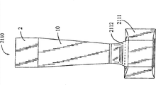
Below with reference to Figure 21 and 21A, show two-part air-flow constrictor.First paragraph constrictor 2111 be level and lead to commutator 8.Second segment constrictor 2112 is vertical and leads to flight capsule 10.Simulator 2110 can be imbedded first paragraph constrictor 2112 underground.The result is so that second segment constrictor 2112 has less noise and height.The present invention can make simulator 2110 have lower overall height.
Below with reference to Figure 22, sectional area 2200 has the flight capsule 2202 that bottom B is comprised of screen cloth 2201.
A kind of embodiment that forms the screen cloth of flight capsule bottom surface is (the stainless steel aviation hawser of the 3/32-17-strand of grid of 60cm * 60cm) that is made into 2 ' * 2 '.The one or both ends of hawser extend through Compress Spring according to concrete application conditions.Wind-tunnel bottom surface shown in 122 hawsers have formed.The quantity of hawser depends on aviator's maximum quantity and other design considerations that the interior plan of shape and size, flight capsule of flight capsule 2202 enters.
The amount of compression of regulating spring to be providing earthward suitable " spring ", thereby security is improved.
Wind-tunnel is observed wall
Have 11 large 1-1/4 " (31mm) acrylic panel, make the effector, aviator and the spectators that are in segmentation/viewing area can see the activity on the flight capsule and flying platform in the illustrated embodiment.The quantity of plate depends on installation.Having large acrylic panel makes spectators can see that the pulpit is inner.
Below with reference to Figure 23, flight capsule 10 has aviator's sensor 2600, and it adopts energy wave 2601 (light, radio, sound, UV etc.) to detect mobile too high and enters aviator in the flight capsule 10.Controller 2602 can be comprised of simple ON/OFF output logic or current modulator or like, and it temporarily reduces air-flow so that the aviator falls in the flight capsule.Promptly leading to extraneous door 2604 can also open by controller 2602.Screen cloth 2605 can also be used to prevent the aviator De Taigao that advances.
Below with reference to Figure 24, another fan diffuser 2700 also can be used as flight capsule.Wall 2701 can be three inches acrylic panels.Oval outlet 2702 has curved edge.
Below with reference to Figure 25, ship 2850 has the simulator 2801 with salt water cooling system 2800.Seawater entrance 2851 leads to heat interchanger 2853 in the simulator by flow governor 2852.Air temperature sensor 2854 is communicated by letter with temperature controller 2802, by control flow governor 2852 air themperature is remained on set point.
Figure 26,27,28 provide the various hawser designs that can form screen cloth.The instruction of basic aerodynamics is that the wing formula profile relative with blunt nosed or flat profile can reduce resistance.As shown in figure 26, hawser 2300 has the standard twisting element core 2301 with external helicoid shape jacket.
As shown in figure 27, hawser 2400 has the distortion twisting element core 2401 that lacks single helical element 2402.
As shown in figure 28, hawser 2500 has the distortion twisting core 2501 that lacks Double-spiral element 2502.
Below with reference to Figure 29, the embodiment of shown hawser 2900 has 18 strands.Strand 2901 forms outer hawser periphery, and has diameter d about equally
1D
1In illustrated embodiment, be approximately 0.4826mm (0.019 inch).Strand L19 finishes outer hawser periphery, and has the d of being different from
1Diameter d
2In embodiment shown in Figure 29, has the larger diameter of about 0.7112mm (0.028 inch) with the strand L19 shown in the solid line.Strand L19a shown in broken lines has the diameter less than strand 2901.
D
2Should with d
1Differ at least 10%, more commonly D
2With d
1Differ 25% or more.At d
2Greater than d
1Those embodiments in, d
2Can be d
1250% of size.Can carry out in a similar fashion the variation of other size values.But d
2More hour, d
2Minimum dimension will utilize the structure Consideration to decide.Strand L19a must have enough sizes, thus can in use not rupture and at least minimally separately keep two adjacent strands 2901.The quantity of strand will depend on the application of adopting hawser.In theory, can according to content disclosed by the invention make have 6 or more multi cord hawser and work thus.
Interior strand 2902,2903 can have the diameter different from strand 2901, and forms the core of hawser 2900.Center strand 2903 can have the diameter different from strand 2902. Interior strand 2902 and 2903 diameter and the diameter d of L19
2Uncorrelated.
Shown in the embodiment of the hawser with L19 2900 in, ratio D
2/ D
1Be approximately 1.47, wherein diameter d
3Than average strand diameter d
4About large 10%.Hawser 2900 is the twisting strand forms with the strand L19 that forms helical ridge shown in Figure 9.
Below with reference to Figure 30, it is d that hawser 3000 has diameter
5The strand solid line L30 of larger neighboring.D in illustrated embodiment
5It is 0.8636mm (0.034 ").D
1With identical among Fig. 5.Ratio D
2/ D
1Be approximately 1.79.Length d
6The about 0.5055mm on the periphery surface scope S (0.0199 inch) in illustrated embodiment.
Also as shown in figure 30, strand L30a is shown in broken lines, diameter d
5Less than D
150%.In this embodiment, two or more strand L30a are used to keep opened gap G.Show the hawser 300 with two strand L30a with skeleton view, it has spiral fluted clearance G among the Figure 34 of formation.
In Figure 32, show another embodiment of hawser 3010.Outer strand 3011, interior strand 3012 and 3013 have formed the primary structure of hawser 3010.The diameter of strand L301a is less than 50% of outer strand 3011 diameters.Be in the single clearance G differently from two strand L301a among Fig. 6, strand L301a is placed on any side of strand 3010, thereby forms two helicla flutes.
Below with reference to Figure 33, show the helical ridge of L19 with skeleton view.
In the operation of wind-tunnel, surpass the air of 20MPH to become the mode at about 90 ° of angles to pass through with the hawser that has formed hawser bottom surface/safety net shown in Figure 22 (2202).In disclosed all ropes, the direction that air-flow produces is not vital to the effect of device.Be different from air-flow and directly advance downwards along cable length, the every other direction that air flows through hawser is considered to cause resistance at least to a certain degree to reduce.
Figure 31 represents to have the hawser 3300 of 15 strands.Strand 3301 forms the neighboring with L31.Strand 3302 and 3303 forms the inner core of hawser 3300.L31 can be than the less (not shown) of strand L31 on diameter.
Disclosed hawser can be used in any wind-tunnel maybe to be needed to adopt in other environment of hawser, and is not only in the recycle wind-tunnel, described hawser when passing air or the resistance ratios that suffers when the hawser at air usually less.
Figure 35 is that expression is as the curve map of the different hawser resistance coefficients of the function of dynamic pressure.In all test hawsers, the diameter of the nearly all strand in the hawser all is roughly 0.019 inch.Line 3401 expression standard twisting hawsers.Line 3403 and 3405 expressions have the hawser 2300 of the spirality strand 2302 that twines around periphery.Line 3402 expressions, d the same with Figure 30
5It is 0.035 inch strand.Line 3404 expressions, d the same with Figure 29
2It is 0.025 strand.
Disclosed hawser usually can be than any obviously larger manufacture of the standard hawser cost of same size.Therefore, by using reducing and corresponding saving that any energy consumes of any resistance that this drag cable produces and noise, all will cause direct cost savings.
Although described device of the present invention with reference to illustrated embodiment, can make numerous modifications and variations and result and still be in the scope of the present invention.Embodiment disclosed herein is not attempted or should be considered as limiting.The embodiment of each device described here has the multiple replacement that is equal to.